Page 3430 of 4087
TR±82
TR±96
TR±104
TR±114
TR±118
TR±120
TR±126
TR±128
TR±132
TR±110
AC±68
ST±13 14
IG±6
IG±7
IG±10
IG±10
EM±22
AT±68
BE±398
IN±32
MATRIX CHART OF PROBLEM SYMPTOMS
When the malfunction code is not confirmed in the diagnostic trouble code ch\
eck and the problem still can not
be confirmed in the basic inspection, then proceed to this step and perfor\
m troubleshooting according to the
numbered order given in the table below.
The circuits indicated by on the matrix chart can be inspected using th\
e TCCS checker.
±
ENGINE TROUBLESHOOTING Matrix Chart of Problem SymptomsTR±39
WhereEverybodyKnowsYourName
Page 3438 of 4087
DIAGNOSTIC CHART
WIRING DIAGRAM
Check resistance of each pickup coils in
distributor
Check for open and short in harness and
connector between ECU and distributor.
Check air gap.
Check and replace ECU.
Replace distributor.
Repair or rep lace harness or connector.
Replace distributor
±
ENGINE TROUBLESHOOTING Circuit InspectionTR±47
WhereEverybodyKnowsYourName
Page 3439 of 4087
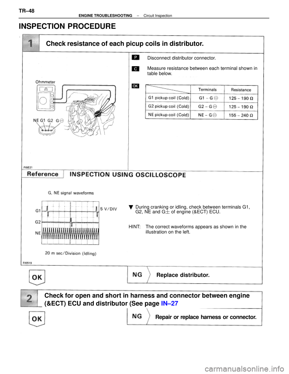
Disconnect distributor connector.
Measure resistance between each terminal shown in
table below.
Check resistance of each picup coils in distributor.
�During cranking or idling, check between terminals G1,
G2, NE and G � of engine (&ECT) ECU.
HINT: The correct waveforms appears as shown in the illustration on the left.
Replace distributor.
Check for open and short in harness and connector between engine
(&ECT) ECU and distributor (See page IN±27
Repair or replace harness or connector.
INSPECTION PROCEDURE
TR±48±
ENGINE TROUBLESHOOTING Circuit Inspection
WhereEverybodyKnowsYourName
Page 3440 of 4087
Remove distributor cap & rotor.
Using SST (G1 and G2 pickups) and a thikness gauge
(NE pickup). measure the air gap between the signal
rotor projection and pickup coil.
SST 09240±00020 fro G1 and G2 pickups
Air gap: 0.2±0.4 mm (0.008±0.016 in.)
Replace distributor.
Check and replace engine (& ECT) ECU.
±
ENGINE TROUBLESHOOTING Circuit InspectionTR±49
WhereEverybodyKnowsYourName
Page 3443 of 4087
OKNG
INSPECTION PROCEDURE
1Check engine speed sensor, No. 1, No. 2 cam position sensor
C
OK
PFor engine speed sensor.
(2) Remove engine under cover.
(2) Disconnected engine speed sensor connector.
For No.1, No. 2 cam position sensor,
(2) Disconnect No. 1, No. 2 cam poisition sensor con-nectors.
Measure resistance of engine speed sencor, No. 1 and
No. 2 cam position sensor.
Replace engine speed sensor, No. 1, No. 2 cam poistion
sensor.
TR±50
±
ENGINE TROUBLESHOOTING Circuit Inspection
WhereEverybodyKnowsYourName
Page 3444 of 4087
OKNG
OKNG
2Check for open and short in harness and connector between engine & ECT ECU an\
d each sen-
sor (See page IN±27).
Repair or replace harness or connector.
3Inspect sensor installation and teeth of signal plate.
Tighen the sensor.
Replace signal plate.
Check and replace engine and ECT ECU.
±
ENGINE TROUBLESHOOTING Circuit InspectionTR±51
WhereEverybodyKnowsYourName
Page 3445 of 4087

CIRCUIT DESCRIPTION
Refer to RPM signal circuit (No. 1) on page TR±46.
Code No.Diagnostic Code Detecting ConditionTrouble Area
13
No NE signal to ECU for 0.1")
Diag. Code 13RPM Signal Circuit (No. 2)
CIRCUIT DESCRIPTION
Refer to RPM signal circuit (No. 1) on page TR±46.
Code No.Diagnostic Code Detecting ConditionTrouble Area
13
No NE signal to ECU for 0.1 sec. or more at
1,000 rpm or more.
�Open or short in NE circuit
�Distributor13
No 12 pulses of NE to ECU during the interval
�Distributor
� ECU
No 12 ulses of NE to ECU during the interval
between G1 and G2 pulses.
�ECU
DIAGNOSTIC CHART
This code indicates that a momentary interruption of the RPM signal from the\
distributor to the ECU has
occurred, but that it is returned to normal. Note that although this problem may \
not necessarily appear
at the time of inspection, it cannot be ignored because this diagnostic co\
de is output, indicating that there
is or was a malfunction in the RPM signal circuit; this ºmalfunctionº\
is usually a loose connector.
The distributor connector and the NE terminal of the ECU connector must the\
refore be checked for the
following:
1. Loose connectors
2. Dirty connector terminals
3. Loose connector terminals
TR±50±
ENGINE TROUBLESHOOTING Circuit Inspection
WhereEverybodyKnowsYourName
Page 3446 of 4087

CIRCUIT DESCRIPTION
Refer to RPM signal circuit (No. 1) on page TR±48.
Code No.Diagnostic Code Detecting ConditionTrouble Area
No NE signal to ECU for 0.1 sec.")
Diag. Code 13RPM Signal Circuit (No.2)
CIRCUIT DESCRIPTION
Refer to RPM signal circuit (No. 1) on page TR±48.
Code No.Diagnostic Code Detecting ConditionTrouble Area
No NE signal to ECU for 0.1 sec. or more at
1,000 rpm or more.
wOpen or short in engine speed sensor
w circuit.
w Engine speed sensor
w ECU
13No 12 pulses of NE to ECU during the interval
between G1 and G2 pulses.
wOpen or short in engine speed sensor
w circuit.
w Mechanical system malfunction (skipping
teeth of timing belt, belt stretched)
w Engine speed sensor
w ECU
Deviation in G (G1, G2) and NE signal contin-
ues for 1 sec. during idling (throttle fully
closed) after engine warmed up.wMechanical system malfunction (skipping
teeth of timing belt, belt stretched)
w No. 1, No. 2 cam position sensor
w ECU
DIAGNOSTIC CHARTDIAGNOSTIC CHART
Inspect sensor installation. Check if any teeth of NE
signal plate are broken
Check valve timing (Check for loose and jumping teeth
of timing belt (See page EM±51)). Tighten the sensor.
Replace signal plate.
Adjust valve timing
(Repair or replace timing belt).
HINT: Perform troubleshooting of diag. code 12 first. If no trouble is found, trouble\
shoot the following mechanical systems.
Check for momentary interruption
(See page TR±23).
TR±52±
ENGINE TROUBLESHOOTING Circuit Inspection
WhereEverybodyKnowsYourName


 and a thikness gauge
(NE pickup). measure the air gap between the signal
rotor projection and pickup coil.
SST 09240±00020 fro G1 and G2")
 Remove engine under cover.
(2) Disconnected engine speed sensor connector.
Fo")
.
Repair or replace harness or connector.
3Inspect sensor installation and t")