Page 814 of 4087

Description
The power source supplies power to each of the vehicle's electrical devices. It is composed of the battery, fuses
and relays, which are located centrally at relay block No. 2 and relay block No. 6 i\
n the engine compartment
and junction block No. 1 relay block No. 4 and relay block No. 5 in the \
cabin near the driver's feet.
Related systems for each Fuse
No.Part NameRelated Systems or Parts
1IGN � Charging System � AIR±BAG System1IGN � Engine
2ST � Starter
3WIPER � Wiper and Washer System
4HTR � Defogger System � A/C System
5ENGINE � Charging System
6RADIO NO. 2 � Audio System � Power Mirror System
� Cigarette Lighter � A/C System
7CIG � Combination Meter System � AIR±BAG System7CIG � Shift Lock System � Theft Deterrent System
� TEL System
8STOP � Stop Light System � Cruise Control System
9TURN � Turn Signal and Hazard
Warning Light System � Cornnering Light System
10MIR HTR � Mirror Heater System
11PANEL � Illumination Light System
12ECU±B � Combination Meter System � AIR±BAG System
� Combination Meter System � ECT System
13GAUGE � Back±Up Light � Transmission Indicator
� Light Failare Sensor � ABS and TRAC
� Power Seat System � Door Lock Control System
� TEL System � Shift Lock System
14ECU±IG � Radiator Fan � Auto Antenna
� Electric Tension Reducer System � Power Steering
� Auto±Tilt away Steering � Cruise Control System
15TAIL � Taillight System � Side Marker15TAIL � Clearance Light
16DOOR � Power Seat System � Luggage Door Opener16DOOR � Door Lock Control System � Fuel Lid Opener System
17IG SWUpstream of ECU±IG, ENGINE, WIP, HTR, TURN, GAUGE, and ST Fuse
18PWR � Power Window System � Sliding Roof System
19ABS NO. 1 � ABS and TRAC
20AM1Upstream of MIR HTR, TAIL, PANEL, STOP, ECUA±B, DOOR and PWR Fuse
21ALTUpstream of DEF, HTR, AM1, and ABS No. 1 Fuse
BE±18±
BODY ELECTRICAL SYSTEM Power Source
WhereEverybodyKnowsYourName
Page 815 of 4087
No.Part NameRelated Systems or Parts
22MAIN � Upstream of ALT±S and EFI Fuse
23AM2 � Charging System � Engine23AM2 � AIR±BAG System
24ABS NO. 2 � ABS and TRAC
25INJ � Charging System � Engine25INJ � AIR±BAG System
26DEF � Defogger System
� Power Seat System � Sliding Roof System
� A/C System � Liquid Crystal Inner Mirror System
27DOME � Combination Meter System � Interior Light System27DOME � ABS and TRAC � Wireless Door Lock Control System
� Cruise Control System � Auto±Tilt away Steering
� Theft Deterrent System
28EFI � Engine
29HAZ HORN � Turn Signal and Hazard Warning Light System29HAZ±HORN � Horn System
30RADIO NO. 1 � Audio System
31TEL � TEL System
32ALT±S � Charging System
33TRAC � ABS and TRAC
34HEAD (RH±LWR) � Headlight System
35HEAD (LH±LWR) � Headlight System
36HEAD (RH±UPR) � Headlight System
37HEAD (LH±UPR) � Headlight System
38HTR � Blow Motor
±
BODY ELECTRICAL SYSTEM Power SourceBE±19
WhereEverybodyKnowsYourName
Page 843 of 4087

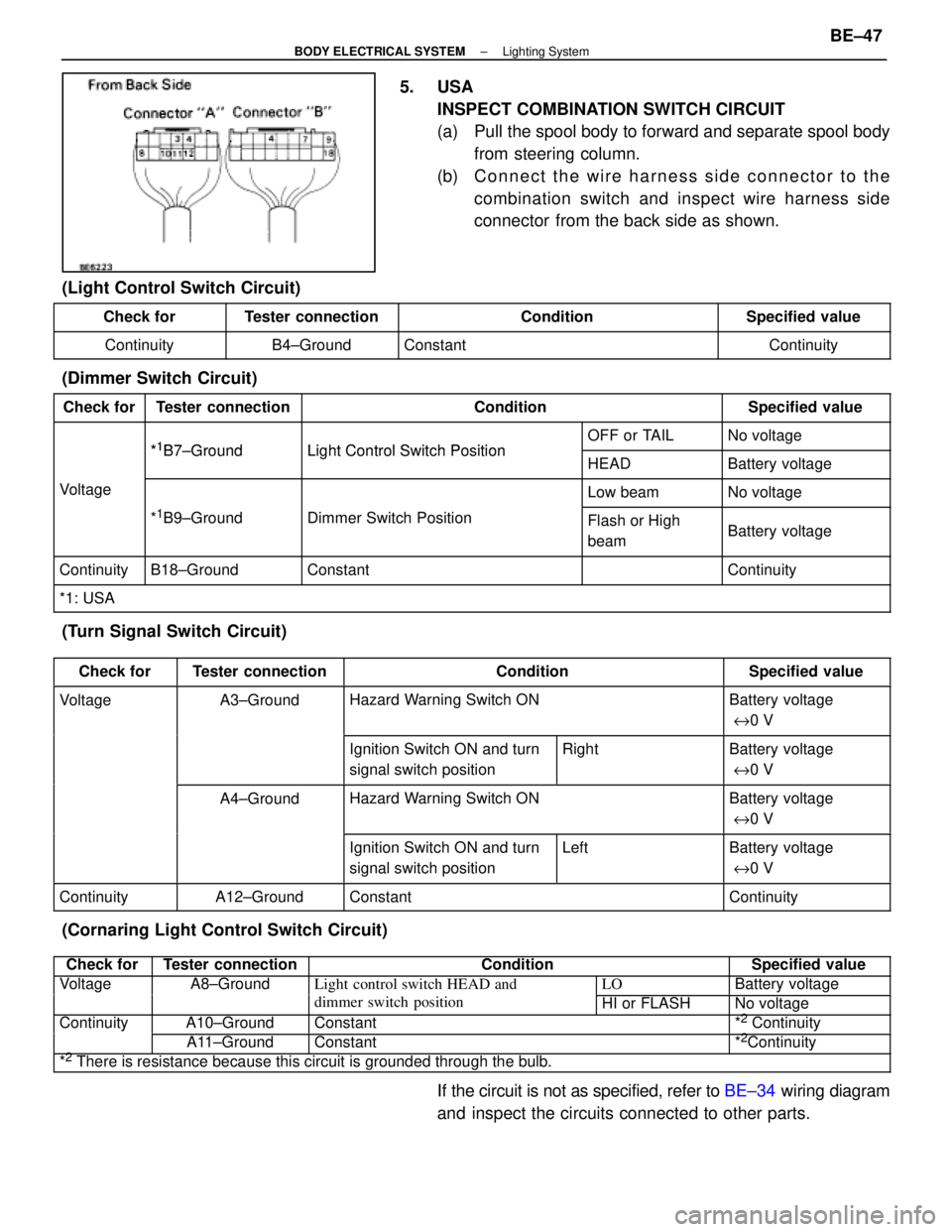
5. USAINSPECT COMBINATION SWITCH CIRCUIT
(a) Pull the spool body to forward and separate spool bodyfrom steering column.
(b) C onnect the wire harness side connector to the
combination switch and inspect wire harness side
connector from the back side as shown.
(Light Control Switch Circuit)
Check forTester connectionConditionSpecified value
ContinuityB4±GroundConstantContinuity
(Dimmer Switch Circuit)
Check forTester connectionConditionSpecified value
*1B7 GroundLight Control Switch PositionOFF or TAILNo voltage*1B7±GroundLight Control Switch PositionHEADBattery voltage
VoltageLow beamNo voltage
*1B9±GroundDimmer Switch PositionFlash or High
beamBattery voltage
ContinuityB18±GroundConstantContinuity
*1: USA
(Turn Signal Switch Circuit)
Check forTester connectionConditionSpecified value
VoltageA3±GroundHazard Warning Switch ONBattery voltage
e 0 V
Ignition Switch ON and turn
signal switch positionRightBattery voltage
e 0 V
A4±GroundHazard Warning Switch ONBattery voltage
e 0 V
Ignition Switch ON and turn
signal switch positionLeftBattery voltage
e 0 V
ContinuityA12±GroundConstantContinuity
(Cornaring Light Control Switch Circuit)
Check forTester connectionConditionSpecified value
VoltageA8±GroundLight control switch HEAD andLOBattery voltagegg
dimmer switch positionHI or FLASHNo voltage
ContinuityA10±GroundConstant*2 Continuityy
A11±GroundConstant*2Continuity
*2 There is resistance because this circuit is grounded through the bulb.
If the circuit is not as specified, refer to BE±34 wiring diagram
and inspect the circuits connected to other parts.
±
BODY ELECTRICAL SYSTEM Lighting SystemBE±47
WhereEverybodyKnowsYourName
Page 852 of 4087

(TAILLIGHT SYSTEM)
Description ± Taillight System
The component parts of this system and their function are as shown in the f\
ollowing table.
�������� ��������Parts Name������������������\
����������� ������������������\
�����������Function
�������� �
�������
��������
Light Control Switch������������������\
����������� �
������������������\
����������
������������������\
�����������
Grounds current from the taillight control relay via the integration rel\
ay, switching each relay
and supplying current to the appropriate bulbs accordance with the switc\
h position.
�������� ��������Taillight Control Relay������������������\
����������� ������������������\
�����������Turned on by signals from the light control switch and supplies current t\
o each bulb.
�������� �
�������
�
�������
��������
Integration Relay
������������������\
����������� �
������������������\
����������
�
������������������\
����������
������������������\
�����������
Carries out ºLight Auto Turn±Offº of the headlights, fog lights and taillights and cuts off cur-
rent to the light control switch in accordance with signals from the GAU\
GE fuse and door
courtesy switch.
�������� �
�������
��������
Light Failure Sensor������������������\
����������� �
������������������\
����������
������������������\
�����������
This sensor senses when a bulb in rear combination light is burnt out an\
d lights up a warning
light.
��������Integration Relay������������������\
������������������� ��������Integration Relay
(Daytime Running
������������������\
����������� ������������������\
�����������
Refer to
BE±30.�������� ��������(y g
Light Relay: CANADA)������������������\
����������� ������������������\
�����������
PARTS LOCATION ± Taillight System
±
BODY ELECTRICAL SYSTEM Lighting SystemBE±53
WhereEverybodyKnowsYourName
Page 858 of 4087
(STOP LIGHT SYSTEM)
DESCRIPTION ± Stoplight System
The component parts of this system and their function are as shown in the f\
ollowing table.
������� �������Parts Name������������������\
������������ ������������������\
������������Function
������� �
������
�������Stop Light Switch
������������������\
������������ �
������������������\
�����������
������������������\
������������
Creates a closed circuit for current from the STOP fuse when the brake pedal is depressed,
thus turning on the stop lights.
������� �
������
�������
Light Failure Sen-
sor������������������\
������������ �
������������������\
�����������
������������������\
������������
This sensor senses when a bulb in rear combination light is burnt out an\
d lights up a warning
light.
PARTS LOCATION ± Stoplight System
±
BODY ELECTRICAL SYSTEM Lighting SystemBE±59
WhereEverybodyKnowsYourName
Page 864 of 4087
(TURN SIGNAL AND HAZARD WARNING
LIGHT SYSTEM)
Description ± TURN SIGNAL AND
HAZARD WARNING LIGHT SYSTEM
The component parts of this system and their function are as shown in the f\
ollowing table.
Parts NameFunction
Turn Signal SwitchSwitches current from the turn signal flasher to the left side or right \
side.
Hazard Warning
SwitchModifies the circuit to the flasher relay and turn signal switch in acco\
rdance with the
respective switch positions.
Turn Signal FlasherReceives current from the hazard warning switch and flashes the turn sig\
nal lights by
switching the current to the lights ON and OFF.
PARTS LOCATION ± TURN SIGNAL
±
BODY ELECTRICAL SYSTEM Lighting SystemBE±65
WhereEverybodyKnowsYourName
Page 865 of 4087
WIRING AND CONNECTOR DIAGRAMS
Turn Signal and Hazard Warning Lights
BE±66±
BODY ELECTRICAL SYSTEM Lighting System
WhereEverybodyKnowsYourName
Page 867 of 4087

Parts Inspection (Turn and Hazard)
(Combination Switch Assembly)
(See page BE±39)
HINT: Inspect turn signal light switch.
(Turn Signal Flasher)
REMOVAL AND INSTALLATION OF TURN
SIGNAL FLASHER
(See page BE±16 )
INSPECTION OF TURN SIGNAL
FLASHER
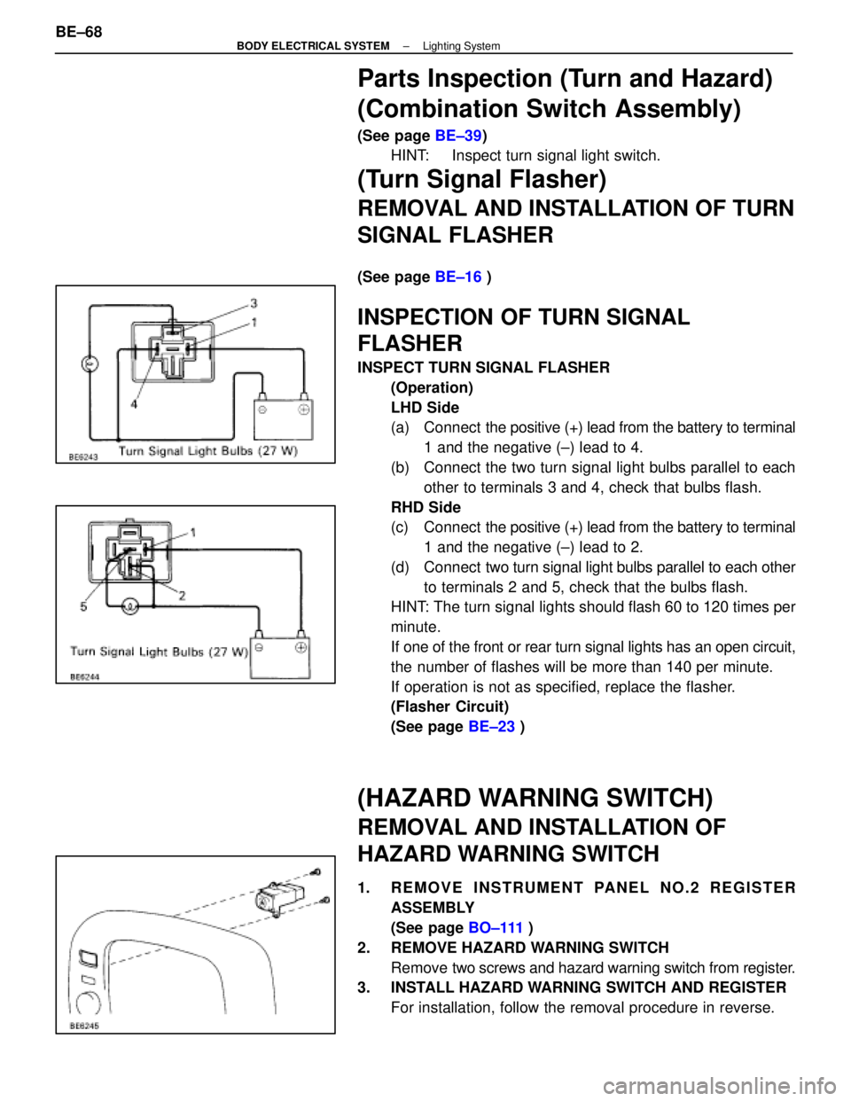
INSPECT TURN SIGNAL FLASHER
(Operation)
LHD Side
(a) Connect the positive (+) lead from the battery to terminal
1 and the negative (±) lead to 4.
(b) Connect the two turn signal light bulbs parallel to each other to terminals 3 and 4, check that bulbs flash.
RHD Side
(c) Connect the positive (+) lead from the battery to terminal
1 and the negative (±) lead to 2.
(d) Connect two turn signal light bulbs parallel to each other
to terminals 2 and 5, check that the bulbs flash.
HINT: The turn signal lights should flash 60 to 120 times per
minute.
If one of the front or rear turn signal lights has an open circuit,
the number of flashes will be more than 140 per minute.
If operation is not as specified, replace the flasher.
(Flasher Circuit)
(See page BE±23 )
(HAZARD WARNING SWITCH)
REMOVAL AND INSTALLATION OF
HAZARD WARNING SWITCH
1. REMOVE INSTRUMENT PANEL NO.2 REGISTER
ASSEMBLY
(See page BO±111 )
2. REMOVE HAZARD WARNING SWITCH Remove two screws and hazard warning switch from register.
3. INSTALL HAZARD WARNING SWITCH AND REGISTER
For installation, follow the removal procedure in reverse.
BE±68
±
BODY ELECTRICAL SYSTEM Lighting System
WhereEverybodyKnowsYourName