Page 1831 of 4087
PREPARATION FOR DISASSEMBLY
(See Components on pages EM±74 and 75)1. (M/T) REMOVE FLYWHEEL
2. (A/T) REMOVE DRIVE PLATE
Remove the eight bolts, two spacers and drive plate.
3. INSTALL ENGINE TO ENGINE STAND FOR DISASSEMBLY
4. REMOVE GENERATOR
5. REMOVE THROTTLE BODY WITH INTAKE AIR CONNECTOR (See pages EM±10 to 11)
6. REMOVE TIMING BELT AND PULLEYS (See pages EM±24 to 26)
7. REMOVE WATER PUMP AND BY±PASS HOSE
8. REMOVE FUEL PRESSURE PULSATION DAMPER
9. REMOVE CYLINDER HEAD (See pages EM±36 to 40)
10. REMOVE FUEL PIPE SUPPORT
11. REMOVE OIL PRESSURE SWITCH AND KNOCK SENSORS
SST 09816±30010
12. REMOVE LH ENGINE MOUNTING BRACKET
13. REMOVE RH ENGINE MOUNTING BRACKET
14. REMOVE OIL FILTER BRACKET (a) Remove the union bolt and oil filter bracket.
(b) Remove the gasket from the union bolt.
(c) Remove the O±ring from the oil filter bracket.
15. REMOVE OIL PUMP (See page LU±10)
EM±76
±
ENGINE MECHANICAL Cylinder Block
WhereEverybodyKnowsYourName
Page 1856 of 4087

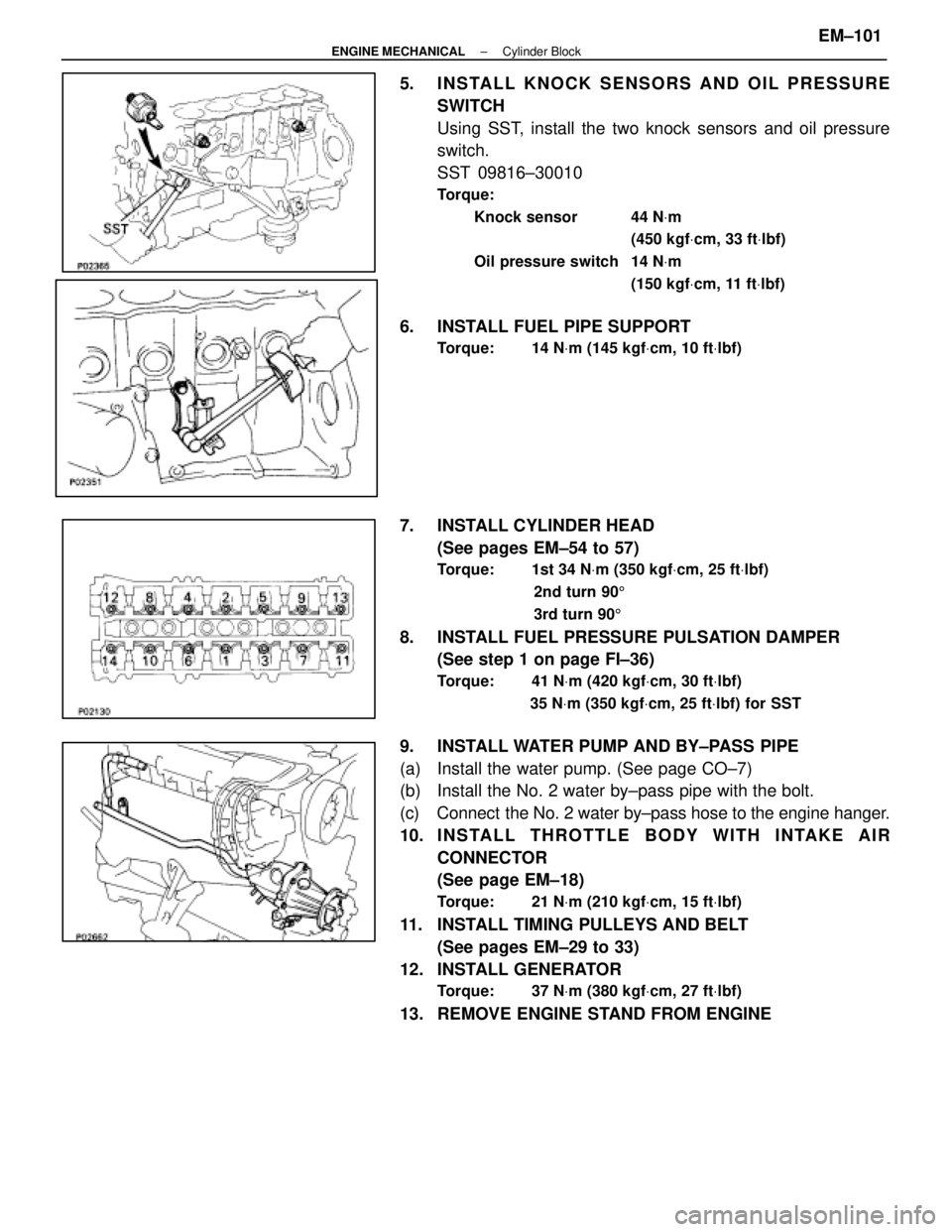
5. INSTALL KNOCK SENSORS AND OIL PRESSURESWITCH
Using SST, install the two knock sensors and oil pressure
switch.
SST 09816±30010
Torque:
Knock sensor 44 N Vm
(450 kgf Vcm, 33 ft Vlbf)
Oil pressure switch 14 N Vm
(150 kgf Vcm, 11 ft Vlbf)
6. INSTALL FUEL PIPE SUPPORT
Torque: 14 N Vm (145 kgf Vcm, 10 ft Vlbf)
7. INSTALL CYLINDER HEAD
(See pages EM±54 to 57)
Torque: 1st 34 N Vm (350 kgf Vcm, 25 ft Vlbf)
2nd turn 90 5
3rd turn 90 5
8. INSTALL FUEL PRESSURE PULSATION DAMPER
(See step 1 on page FI±36)
Torque: 41 N Vm (420 kgf Vcm, 30 ft Vlbf)
35 N Vm (350 kgf Vcm, 25 ft Vlbf) for SST
9. INSTALL WATER PUMP AND BY±PASS PIPE
(a) Install the water pump. (See page CO±7)
(b) Install the No. 2 water by±pass pipe with the bolt.
(c) Connect the No. 2 water by±pass hose to the engine hanger.
10. INSTALL THROTTLE BODY WITH INTAKE AIR
CONNECTOR
(See page EM±18)
Torque: 21 N Vm (210 kgf Vcm, 15 ft Vlbf)
11. INSTALL TIMING PULLEYS AND BELT
(See pages EM±29 to 33)
12. INSTALL GENERATOR
Torque: 37 N Vm (380 kgf Vcm, 27 ft Vlbf)
13. REMOVE ENGINE STAND FROM ENGINE
±
ENGINE MECHANICAL Cylinder BlockEM±101
WhereEverybodyKnowsYourName
Page 1872 of 4087

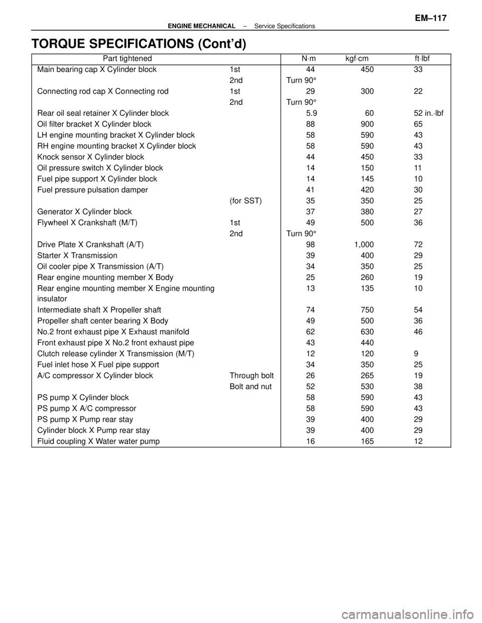
TORQUE SPECIFICATIONS (Cont'd)
����������������� �����������������Part tightened������ ����������� �����NVm������ ������kgf Vcm������ ������ft Vlbf
����������������� �����������������Main bearing cap X Cylinder block������ ������1st����� �����44������ ������450������ ������33
����������������� ����������������������� ������2nd����� �����Turn 90 5������ ������������ ������
����������������� �����������������Connecting rod cap X Connecting rod������ ������1st����� �����29������ ������300������ ������22
�����������������������2nd�����Turn 905����������������������������� �����������������Rear oil seal retainer X Cylinder block������ ����������� �����5.9������ ������60������ ������52 in.Vlbf����������������� �����������������Oil filter bracket X Cylinder block������ ����������� �����88������ ������900������ ������65����������������� �����������������LH engine mounting bracket X Cylinder block������ ����������� �����58������ ������590������ ������43����������������� �����������������RH engine mounting bracket X Cylinder block������ ����������� �����58������ ������590������ ������43
����������������� �����������������Knock sensor X Cylinder block������ ����������� �����44������ ������450������ ������33
����������������� �����������������Oil pressure switch X Cylinder block������ ����������� �����14������ ������150������ ������11
����������������� �����������������Fuel pipe support X Cylinder block������ ����������� �����14������ ������145������ ������10
����������������� �����������������Fuel pressure pulsation damper������ ����������� �����41������ ������420������ ������30
����������������� ����������������������� ������(for SST)����� �����35������ ������350������ ������25
����������������� �����������������Generator X Cylinder block������ ����������� �����37������ ������380������ ������27
�����������������Flywheel X Crankshaft (M/T)������1st�����49������500������36����������������� ����������������������� ������2nd����� �����Turn 90 5������ ������������ ������
����������������� �����������������Drive Plate X Crankshaft (A/T)������ ����������� �����98������ ������1,000������ ������72����������������� �����������������Starter X Transmission������ ����������� �����39������ ������400������ ������29����������������� �����������������Oil cooler pipe X Transmission (A/T)������ ����������� �����34������ ������350������ ������25
����������������� �����������������Rear engine mounting member X Body������ ����������� �����25������ ������260������ ������19
����������������� �
����������������
�����������������
Rear engine mounting member X Engine mounting
insulator������ �
�����
������
����� �
����
�����
13������ �
�����
������
135������ �
�����
������
10
����������������� �����������������Intermediate shaft X Propeller shaft������ ����������� �����74������ ������750������ ������54
����������������� �����������������Propeller shaft center bearing X Body������ ����������� �����49������ ������500������ ������36
�����������������No.2 front exhaust pipe X Exhaust manifold�����������62������630������46����������������� �����������������Front exhaust pipe X No.2 front exhaust pipe������ ����������� �����43������ ������440������ ������
����������������� �����������������Clutch release cylinder X Transmission (M/T)������ ����������� �����12������ ������120������ ������9����������������� �����������������Fuel inlet hose X Fuel pipe support������ ����������� �����34������ ������350������ ������25����������������� �����������������A/C compressor X Cylinder block������ ������Through bolt����� �����26������ ������265������ ������19
����������������� ����������������������� ������Bolt and nut����� �����52������ ������530������ ������38
����������������� �����������������PS pump X Cylinder block������ ����������� �����58������ ������590������ ������43
����������������� �����������������PS pump X A/C compressor������ ����������� �����58������ ������590������ ������43
����������������� �����������������PS pump X Pump rear stay������ ����������� �����39������ ������400������ ������29
����������������� �����������������Cylinder block X Pump rear stay������ ����������� �����39������ ������400������ ������29
����������������� �����������������Fluid coupling X Water water pump������ ����������� �����16������ ������165������ ������12
±
ENGINE MECHANICAL Service SpecificationsEM±117
WhereEverybodyKnowsYourName
Page 1879 of 4087

INSPECTION OF INJECTORS
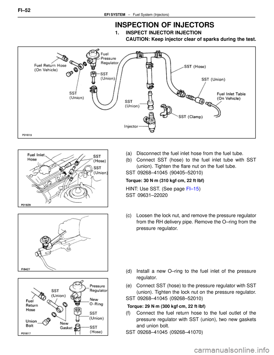
1. INSPECT INJECTOR INJECTIONCAUTION: Keep injector clear of sparks during the test.
(a) Disconnect the fuel inlet hose from the fuel tube.
(b) Connect SST (hose) to the fuel inlet tube with SST(union). Tighten the flare nut on the fuel tube.
SST 09268±41045 (90405±52010)
Torque: 30 N Vm (310 kgf Vcm, 22 ft Vlbf)
HINT: Use SST. (See page FI±15)
SST 09631±22020
(c) Loosen the lock nut, and remove the pressure regulator from the RH delivery pipe. Remove the O±ring from the
pressure regulator.
(d) Install a new O±ring to the fuel inlet of the pressure regulator.
(e) Connect SST (hose) to the pressure regulator with SST (union). Tighten the lock nut on the pressure regulator.
SST 09268±41045 (09268±52010)
Torque: 29 N Vm (300 kgf Vcm, 22 ft Vlbf)
(f) Connect the fuel return hose to the fuel outlet of the
pressure regulator with SST (union), two new gaskets
and union bolt.
SST 09268±41045 (09268±41070)
FI±52EFI SYSTEM ± Fuel System (Injectors)
WhereEverybodyKnowsYourName
Page 1881 of 4087

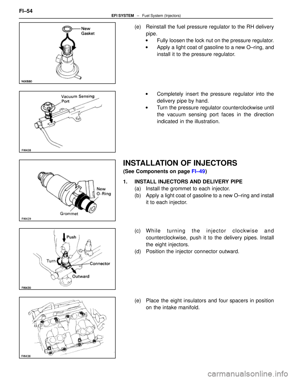
(e) Reinstall the fuel pressure regulator to the RH deliverypipe.
w Fully loosen the lock nut on the pressure regulator.
w Apply a light coat of gasoline to a new O±ring, and
install it to the pressure regulator.
w Completely insert the pressure regulator into the
delivery pipe by hand.
w Turn the pressure regulator counterclockwise until
the vacuum sensing port faces in the direction
indicated in the illustration.
INSTALLATION OF INJECTORS
(See Components on page FI±49)
1. INSTALL INJECTORS AND DELIVERY PIPE (a) Install the grommet to each injector.
(b) Apply a light coat of gasoline to a new O±ring and install
it to each injector.
(c) W h i l e t u r n i n g t h e i n j e c t o r c l o c k w i s e a n d counterclockwise, push it to the delivery pipes. Install
the eight injectors.
(d) Position the injector connector outward.
(e) Place the eight insulators and four spacers in position on the intake manifold.
FI±54
EFI SYSTEM
± Fuel System (Injectors)
WhereEverybodyKnowsYourName
Page 1882 of 4087
(f) Place the eight injectors and two delivery pipesassembly in position on the intake manifold.
(g) Temporarily install the c onnector bracket and four
mounting bolts.
(h) Check that the injectors rotate smoothly.
HINT: If injectors do not rotate smoothly, the probable cause
is incorrect installation of O±rings. Replace the O±rings.
(i) Position the injector connector outward.
(j) Tighten the four bolts holding the delivery pipes to the intake manifold.
Torque: 18 N Vm (185 kgf Vcm, 13 ft Vlbf)
2. INSTALL FUEL RETURN PIPE
(a) Temporarily install the return pipe with the bolt, two
gaskets and union bolt.
(b) Tighten the union bolt holding the return pipe to the pressure regulator.
Torque: 35 N Vm (360 kgf Vcm, 26 ft Vlbf)
(c) Tighten the bolt holding the return pipe to the LH cylinder
head.
3. TIGHTEN LOCK NUT ON FUEL PRESSURE REGULATOR
Torque: 29 N Vm (300 kgf Vcm, 22 ft Vlbf)
FI±55EFI SYSTEM ± Fuel System (Injectors)
WhereEverybodyKnowsYourName
Page 1895 of 4087
Fuel Pressure Pulsation Damper
COMPONENTS FOR REMOVAL AND
INSTALLATION
FI±58 ± Fuel System (Fuel Pressure Pulsation Damper)EFI SYSTEM
WhereEverybodyKnowsYourName
Page 1896 of 4087
REMOVAL OF FUEL PRESSURE
PULSATION DAMPER
(See Component on page FI±58)
1. DISCONNECT CABLE FROM NEGATIVE TERMINAL OF BATTERY
CAUTION: Work must be started after approx. 20 se-
conds or longer from the time the ignition switch is
turned to the ºLOCKº position and the negative (±) termi-
nal cable is disconnected from the battery.
2. REMOVE UPPER HIGH±TENSION CORD COVER (a) Remove the two mounting bolts.
(b) Disconnect the front side claw groove of the cord coverfrom the claw of the lower cover, and remove the cord
cover.
3. REMOVE LH ENGINE WIRE COVER Remove the two bolts and engine wire cover.
4. REMOVE FUEL PRESSURE PULSATION DAMPER (a) Remove the pulsation damper and upper gasket.
(b) Disconnect the fuel inlet hose from the delivery pipe,and remove the lower gasket. FI±59
EFI SYSTEM
± Fuel System (Fuel Pressure Pulsation Damper)
WhereEverybodyKnowsYourName