Page 1735 of 4087

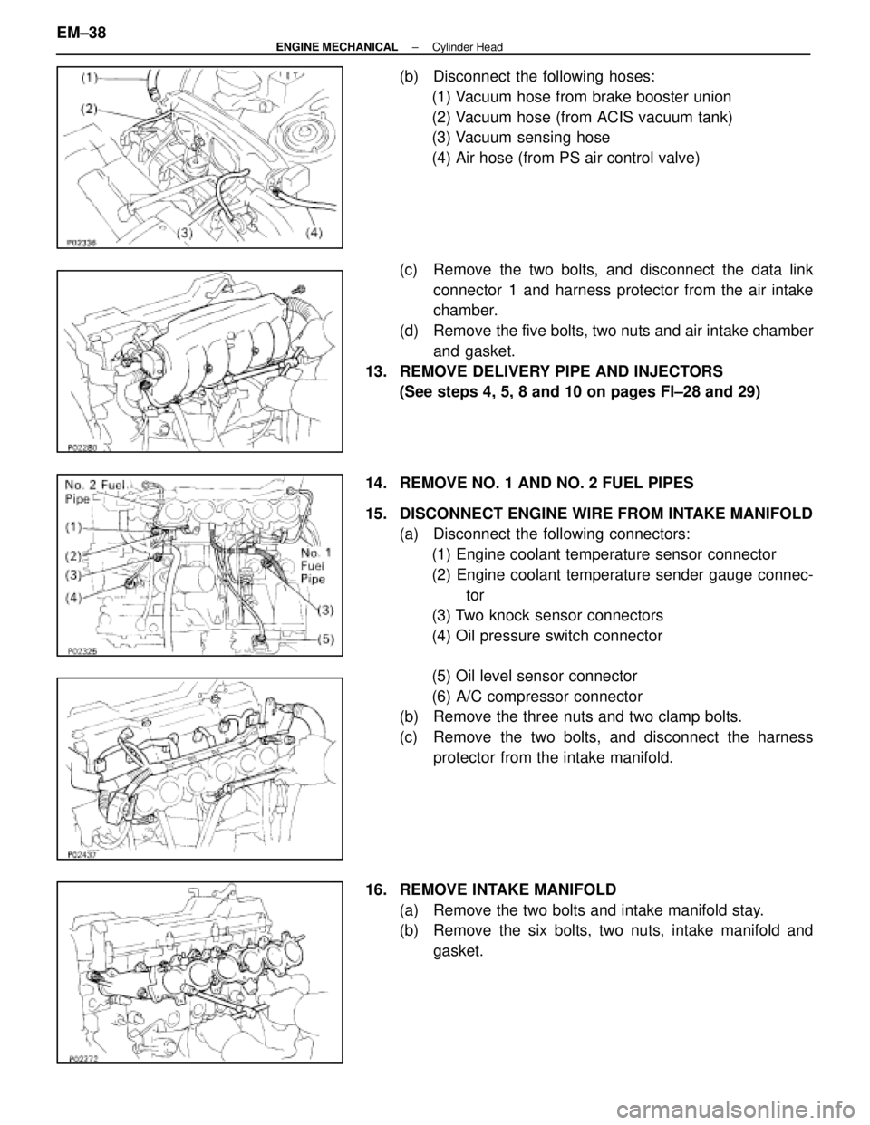
(b) Disconnect the following hoses:(1) Vacuum hose from brake booster union
(2) Vacuum hose (from ACIS vacuum tank)
(3) Vacuum sensing hose
(4) Air hose (from PS air control valve)
(c) Remove the two bolts, and disconnect the data link connector 1 and harness protector from the air intake
chamber.
(d) Remove the five bolts, two nuts and air intake chamber and gasket.
13. REMOVE DELIVERY PIPE AND INJECTORS (See steps 4, 5, 8 and 10 on pages FI±28 and 29)
14. REMOVE NO. 1 AND NO. 2 FUEL PIPES
15. DISCONNECT ENGINE WIRE FROM INTAKE MANIFOLD (a) Disconnect the following connectors:
(1) Engine coolant temperature sensor connector
(2) Engine coolant temperature sender gauge connec- tor
(3) Two knock sensor connectors
(4) Oil pressure switch connector
(5) Oil level sensor connector
(6) A/C compressor connector
(b) Remove the three nuts and two clamp bolts.
(c) Remove the two bolts, and disconnect the harness
protector from the intake manifold.
16. REMOVE INTAKE MANIFOLD (a) Remove the two bolts and intake manifold stay.
(b) Remove the six bolts, two nuts, intake manifold andgasket.
EM±38
±
ENGINE MECHANICAL Cylinder Head
WhereEverybodyKnowsYourName
Page 1756 of 4087

8. CONNECT ENGINE WIRE TO INTAKE MANIFOLD(a) Install the harness protector to the intake manifold withthe two bolts.
(b) Install the three clamp bolts and two nuts.
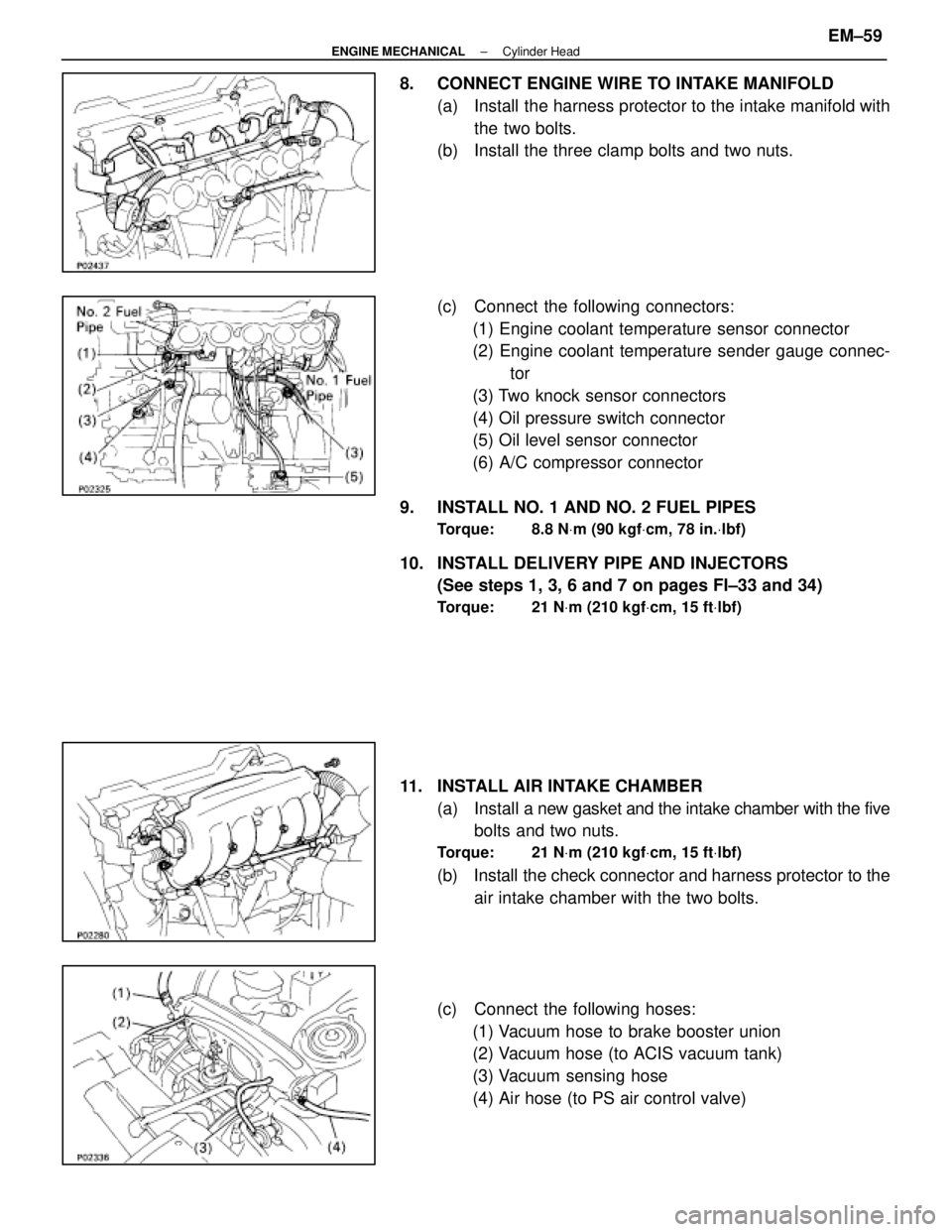
(c) Connect the following connectors:
(1) Engine coolant temperature sensor connector
(2) Engine coolant temperature sender gauge connec- tor
(3) Two knock sensor connectors
(4) Oil pressure switch connector
(5) Oil level sensor connector
(6) A/C compressor connector
9. INSTALL NO. 1 AND NO. 2 FUEL PIPES
Torque: 8.8 N Vm (90 kgf Vcm, 78 in. Vlbf)
10. INSTALL DELIVERY PIPE AND INJECTORS
(See steps 1, 3, 6 and 7 on pages FI±33 and 34)
Torque: 21 N Vm (210 kgf Vcm, 15 ft Vlbf)
11. INSTALL AIR INTAKE CHAMBER
(a) Install a new gasket and the intake chamber with the five
bolts and two nuts.
Torque: 21 N Vm (210 kgf Vcm, 15 ft Vlbf)
(b) Install the check connector and harness protector to the
air intake chamber with the two bolts.
(c) Connect the following hoses: (1) Vacuum hose to brake booster union
(2) Vacuum hose (to ACIS vacuum tank)
(3) Vacuum sensing hose
(4) Air hose (to PS air control valve)
±
ENGINE MECHANICAL Cylinder HeadEM±59
WhereEverybodyKnowsYourName
Page 1763 of 4087
9. REMOVE TIMING BELT REAR PLATESRemove the two bolts and rear plate. Remove the two rear
plates.
10. REMOVE VACUUM PIPE (a) Disconnect the following hoses:(1) (USA Spec.)
Vacuum hose from throttle body
(2) (Exc. USA Spec.) Three vacuum hoses from throttle body
(3) Vacuum hose from fuel pressure regulator
(4) Two vacuum hoses from VSV for fuel pressure con-
trol system
(5) (Exc. USA Spec.) Two vacuum hoses from EGR vacuum modulator
(6) Two vacuum hoses (from VSV for EVAP system)
from vacuum pipe
(7) Vacuum hose (from VSV for fuel pressure control system) from air intake chamber
(8) Vacuum hose (from charcoal canister) from vacu-
um pipe.
(b) Remove the two bolts, the vacuum pipe and vacuum hoses assembly.
EM±62
±
ENGINE MECHANICAL Cylinder Heads
WhereEverybodyKnowsYourName
Page 1766 of 4087

(b) Remove the two mounting bolts and two mounting nuts,and disconnect the throttle body from the air intake
chamber.
(c) Disconnect the following hoses, and remove the throttle body:
(1) PCV hose from throttle body
(2) Water by±pass hose from throttle body
(d) Remove the throttle body gasket.
17. DISCONNECT VACUUM HOSES Disconnect the following hoses:(1) Vacuum hose from brake booster union
(2) Vacuum hose (from VSV for heater water valve)
from air intake chamber
18. REMOVE ACCELERATOR BRACKET Remove the bolt, stud bolt and bracket.
19. REMOVE BRAKE BOOSTER UNION
Remove the union bolt, union and two gaskets.
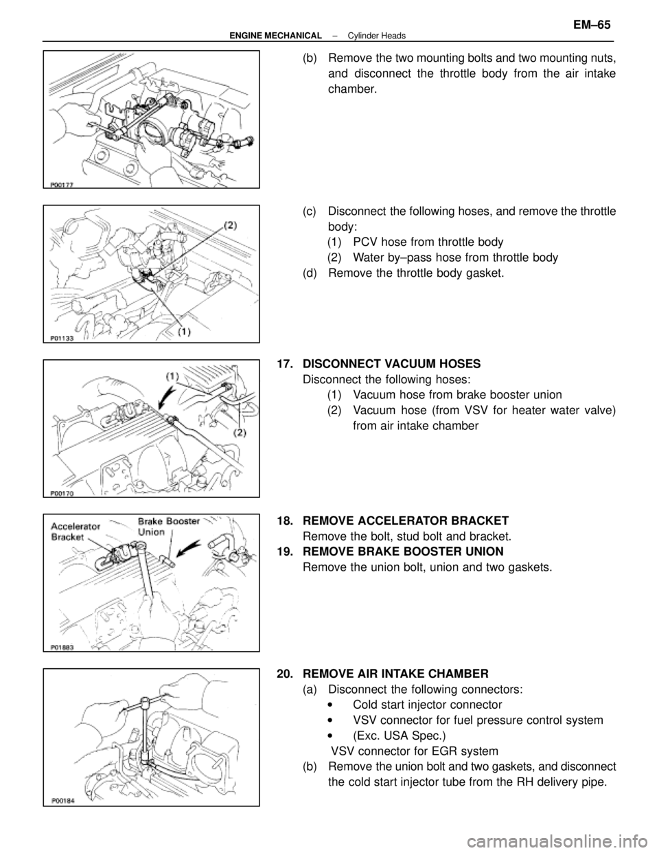
20. REMOVE AIR INTAKE CHAMBER (a) Disconnect the following connectors:w Cold start injector connector
w VSV connector for fuel pressure control system
w (Exc. USA Spec.)
VSV connector for EGR system
(b) Remove the union bolt and two gaskets, and disconnect
the cold start injector tube from the RH delivery pipe.
±
ENGINE MECHANICAL Cylinder HeadsEM±65
WhereEverybodyKnowsYourName
Page 1767 of 4087
(c) Remove the two bolts and gaskets, and disconnect theEGR pipe from the air intake chamber.
(d) Remove the four mounting bolts, eight mounting nuts and following parts:
(1) VSV for fuel pressure control system
(2) (Exc. USA Spec.)
VSV for EGR system
(3) A/T throttle cable bracket
(e) Disconnect the check (ºDIAGNOSISº) connector from
the intake chamber.
(f) Remove the air intake chamber and four gaskets.
(g) Remove the three bolts, the cold start injector, tube, lead
wire assembly and gasket.
21. DISCONNECT HEATER WATER HOSES Disconnect the following hoses:(1) Water hose from water by±pass pipe
(2) Water hose from rear water by±pass joint
22. DISCONNECT FUEL INLET HOSE FROM LH DELIVERY PIPE
Remove the pulsation damper and two gaskets, and discon-
nect the inlet hose.
23. D I S C O N N E C T F U E L R E T U R N H O S E F R O M F U E L RETURN PIPE
EM±66
±
ENGINE MECHANICAL Cylinder Heads
WhereEverybodyKnowsYourName
Page 1807 of 4087
(i) Tighten the four mounting nuts.
Torque: 18 NVm (185 kgf Vcm, 13 ft Vlbf)
23. INSTALL FUEL RETURN PIPE
(a) Temporarily install the return pipe with the bolt, two newgaskets and union bolt.
(b) Tighten the union bolt holding the return pipe to the fuel pressure regulator.
Torque: 35 N Vm (360 kgf Vcm, 26 ft Vlbf)
(c) Tighten the bolt holding the return pipe to the LH cylinder
head.
24. INSTALL ENGINE WIRE TO DELIVERY PIPES, REAR WATER BY±PASS JOINT AND RH CYLINDER HEAD
(a) Connect the eight injector connectors.
(b) Install the two engine wire connectors to connectorsbracket on the LH delivery pipe.
(c) Install the engine wire to the RH cylinder head with the two bolts.
(d) Install the engine wire to the rear water by±pass joint
with the two bolts.
(e) Install the engine wire to the delivery pipes with the four bolts.
EM±106
±
ENGINE MECHANICAL Cylinder Heads
WhereEverybodyKnowsYourName
Page 1809 of 4087

(b) Place four new gaskets on the intake manifold.
HINT: Gaskets can only be used twice before being replaced.
(c) Place the air intake chamber on the intake manifold.
(d) Temporarily connect the EGR pipe to the air intakechamber with a new gasket and the two bolts.
HINT: Use bolts 20 mm (0.79 in.) in length.
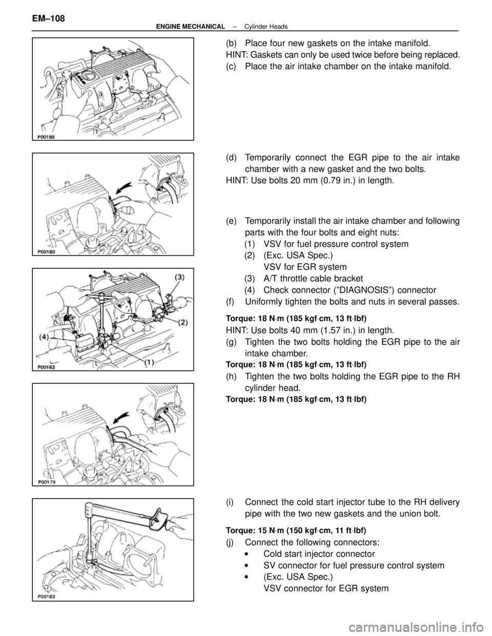
(e) Temporarily install the air intake chamber and following
parts with the four bolts and eight nuts:
(1) VSV for fuel pressure control system
(2) (Exc. USA Spec.) VSV for EGR system
(3) A/T throttle cable bracket
(4) Check connector (ºDIAGNOSISº) connector
(f) Uniformly tighten the bolts and nuts in several passes.
Torque: 18 N Vm (185 kgf Vcm, 13 ft Vlbf)
HINT: Use bolts 40 mm (1.57 in.) in length.
(g) Tighten the two bolts holding the EGR pipe to the air
intake chamber.
Torque: 18 N Vm (185 kgf Vcm, 13 ft Vlbf)
(h) Tighten the two bolts holding the EGR pipe to the RH
cylinder head.
Torque: 18 N Vm (185 kgf Vcm, 13 ft Vlbf)
(i) Connect the cold start injector tube to the RH delivery
pipe with the two new gaskets and the union bolt.
Torque: 15 N Vm (150 kgf Vcm, 11 ft Vlbf)
(j) Connect the following connectors:
w Cold start injector connector
w SV connector for fuel pressure control system
w (Exc. USA Spec.)
VSV connector for EGR system
EM±108
±
ENGINE MECHANICAL Cylinder Heads
WhereEverybodyKnowsYourName
Page 1813 of 4087
(c) Connect the following hoses:(1) Water by±pass pipe hose to ISC valve
(2) Water by±pass pipe hose to water by±pass pipe (from rear water by±pass joint)
(3) Two vacuum hoses to VSV for EGR system
40. INSTALL VACUUM PIPE (a) Install the vacuum pipe, vacuum hoses assembly andEGR water by±pass pipe (USA spec. only) with the two
bolts.
(b) Connect the following hoses: (1) (USA Spec.) Vacuum hose to throttle body
(2) (Exc. USA Spec.) Three vacuum hoses to throttle body
(3) Vacuum hose to fuel pressure regulator
(4) Two vacuum hoses to VSV for fuel pressure control system
(5) (Exc. USA Spec.) Two vacuum hoses to EGR vacuum modulator
(6) Two vacuum hoses (from VSV for EVAP system) to vacuum pipe
(7) Vacuum hose (from VSV for fuel pressure control system) to air intake chamber
(8) Vacuum hose (from charcoal canister) to vacuum pipe
EM±112
±
ENGINE MECHANICAL Cylinder Heads
WhereEverybodyKnowsYourName