Page 3170 of 4087

2HEAT METHOD: When the problem seems to occur when the suspect area is heate\
d.
Heat the component that is likely the cause of the mal-
function with a hair dryer or similar object. Check to see
if the malfunction will occur.
Notice:
�Do not heat to more than 60 �C (140 �F) (Tempera-
ture limit that the component can be touched with a
hand.)
� Do not apply heat directly to any part in the ECU.
3WATER SPRINKLING METHOD: When the malfunction seems to occur on a rainy day or in
a high±humidity condition.
Sprinkle water onto the vehicle and check to see if the
malfunction will occur.
Notice: Never apply water directly onto the
electronic components.
HINT:
�If the vehicle is subject to water leakage, the leaked
water may contaminate the ECU. When testing a ve-
hicle with a water leakage problem, special caution
must be paid.
4OTHER: When a malfunction seems to occur when electrical load is excessive.
Turn on all electrical loads including the heater blower,
headlights, rear window defogger, etc. and check to see
if the malfunction will occur.
RS±66±
SUPPLEMENTAL RESTRAINT SYSTEM TROUBLESHOOTING
WhereEverybodyKnowsYourName
Page 3171 of 4087

DIAGNOSTIC TROUBLE CODE MATRIX CHART
If a malfunction code is displayed during the diagnostic trouble code chec\
k, check the circuit listed for that
code in the table below (Proceed to the page given for that circuit).
����� �����DTC No.������������������\
��������� ������������������\
���������Diagnosis������ ������Page
����� �����(Normal)*1������������������\
��������� ������������������\
���������� Source voltage drop������ ������RS±68
����� �����11������������������\
��������� ������������������\
���������� Short in squib circuit or front airbag sensor circuit (to ground)������ ������RS±70
����� �����12������������������\
��������� ������������������\
���������� Short in squib circuit or front airbag sensor circuit (to B+)������ ������RS±78
����� �����13������������������\
��������� ������������������\
���������� Short in squib circuit (between D+ wire harness and D± wire harness\
)������ ������RS±85
����� �����14������������������\
��������� ������������������\
���������� Open in squib circuit (between D+ wire harness and D± wire harness)\
������ ������RS±92
����� �����15������������������\
��������� ������������������\
���������� Open in front airbag sensor circuit������ ������RS±97
����� �����22*2������������������\
��������� ������������������\
���������� SRS warning light system malfunction������ ������RS±102
����� �����31������������������\
��������� ������������������\
���������� Center airbag sensor assembly malfunction������ ������RS±108
����� �����53������������������\
��������� ������������������\
���������� Short in squib circuit (between P+ wire harness and P± wire harness\
)������ ������RS±110
����� �����54������������������\
��������� ������������������\
���������� Open in squib circuit (between P+ wire harness and P± wire harness)\
������ ������RS±115
HINT:
*
1 When the SRS warning light remains lit up and the diagnostic trouble co\
de is the normal code, this means
a source voltage drop.
*
2 Code 22 is recorded when a malfunction occurs in the SRS warning light \
system. If an open malfunction
occurs in the SRS warning light system, the SRS warning light does not light up, s\
o that until the malfunction
is repaired, the diagnostic trouble code (including 22) cannot be conf\
irmed.
PROBLEM SYMPTOM CHART
Proceed with troubleshooting of each circuit in the table below.
������������������\
� ������������������\
�Problem Symptom������������� �������������Inspection Item������ ������Page
������������������\
� �
������������������
������������������\
�
�
With the ignition switch at ACC or ON, the SRS warning light
sometimes lights up after approx. 6 seconds have elapsed� SRS warning light system
(Always lit upwhen ignition switch isRS±119������������������\
� �
������������������
������������������\
�
�
SRS warning light lights up even when ignition switch is in
the LOCK position (Always lit up when ignition switch is
LOCK position)RS±11 9
������������������\
� ������������������\
�� Diagnostic trouble code not displayed.� Tc terminal circuitRS±121
������������������\
� ������������������\
�� Diagnostic trouble code continuously displayed.� Tc terminal circuitRS±121
±
SUPPLEMENTAL RESTRAINT SYSTEM TROUBLESHOOTINGRS±67
WhereEverybodyKnowsYourName
Page 3172 of 4087
Source Voltage Drop
CIRCUIT DESCRIPTION
The supplemental restraint system is equipped with a voltage ± increase \
circuit (DC±DC converter) in the cente")
WIRING DIAGRAM
CIRCUIT INSPECTION
DTC(Normal)Source Voltage Drop
CIRCUIT DESCRIPTION
The supplemental restraint system is equipped with a voltage ± increase \
circuit (DC±DC converter) in the center
airbag sensor assembly in case the source voltage drops.
When the battery voltage drops, the voltage ± increase circuit (DC±DC\
converter) functions to increase the volt-
age of the supplemental restraint system to normal voltage.
The diagnosis system malfunction display for this circuit is different to other circuits ± when the SRS warning
light remains lit up and the diagnostic trouble code is a normal code, source\
voltage drop is indicated. Malfunc-
tion in this circuit is not recorded in the center airbag sensor assembly, and approx. 10 seconds after the source
voltage returns to normal, the SRS warning light automatically goes off.
DTC No.Diagnosis
(Normal)Source voltage drop.
DIAGNOSTIC CHARTDIAGNOSTIC CHART
(See page CH±1).
RS±68±
SUPPLEMENTAL RESTRAINT SYSTEM TROUBLESHOOTING
WhereEverybodyKnowsYourName
Page 3173 of 4087
 terminal cable, andwait at least 90 seconds.
3. Connect battery negative (±) terminal cab")
YESNO
INSPECTION PROCEDURE
1Preparation.
P1. Turn ignition switch LOCK.
2. Disconnect battery negative (±) terminal cable, andwait at least 90 seconds.
3. Connect battery negative (±) terminal cable.
4. Disconnect center airbag sensor assembly con- nector.
5. Turn ignition switch ON. But do not start engine.
6. Measure voltage at IG
2 or ACC on connector wire
harness side of center airbag sensor assembly and
operate electric system (defogger, wiper, headlight,
heater blower, etc.)
Voltage: 6 V ± 11.5 V at IG
2 and ACC.
7. Turn electric system switch OFF.
8. Turn ignition switch LOCK.
9. Disconnect battery negative (±) terminal cable, and wait at least 90 seconds.
10. Remove voltmeter and connect center airbag sen- sor assembly connector.
11. Connect battery negative (±) terminal cable.
2Does SRS warning light turn off after approx. 10 seconds?
C
PTurn ignition switch ACC or ON and wait at least 20 sec-
onds.
Clear malfunction code. Turn ignition switch LOCK and
wait at least 20 seconds.
Operate electric system checked in � (5) and check
that SRS warning light goes off after approx. 10 sec-
onds.
Check diagnostic trouble code, and if a malfunction code
is output, perform trouble shooting according to mal-
function code. If a normal code is output, replace center
airbag sensor assembly.
Check battery and charging system.
(See page CH±1)
±
SUPPLEMENTAL RESTRAINT SYSTEM TROUBLESHOOTINGRS±69
WhereEverybodyKnowsYourName
Page 3205 of 4087

OKNG
OKNG
4Check front airbag sensor.
C
OK
PDisconnect front airbag sensor connector.
Measure resistance between each terminal of front air-
bag sensor.
Notice:
��Do not touch ohmmeter probes strongly against
terminals of front airbag sensor.
� Make sure the front airbag sensor connector is
properly connected.
Replace front airbag sensor.
5Check harness between center airbag sensor assembly and front airbag sen\
sor.
C
OK
P5. Disconnect center airbag sensor assembly con- nector.
6. Using service wires, connect +SR and ±SR, +SL and ±SL on the wire harness side of the center air-
bag sensor assembly connector.
Measure resistance between terminals +SR and ±SR,
+SL and ±SL of harness side connector of front airbag
sensor.
Notice:
�� Lightly t ouch ohmmeter proves at position shown
in illustration.
� Make sure the front airbag sensor connector is
properly connected.
Resistance: Below 1 �
Repair or replace harness or connector between center
airbag sensor assembly and front airbag sensor. (See
page RS±48 ).
Replace front airbag sensor connector (See page RS±48).
±
SUPPLEMENTAL RESTRAINT SYSTEM TROUBLESHOOTINGRS±101
WhereEverybodyKnowsYourName
Page 3206 of 4087

DTC22SRS Warning Light System Malfunction
CIRCUIT DESCRIPTION
The SRS warning light is located on the combination meter.
When the supplemental restraint system is normal, the SRS warning light ligh\
ts up for approx. 6 seconds after
the ignition switch is turned from LOCK position to ACC or ON position, and then turn\
s off automatically. If there
is a malfunction in the supplemental restraint system, the SRS warning l\
ight lights up to inform the driver of the
abnormality.
When terminals Tc and E
1 of the DLC2 are connected, the diagnostic trouble code is displayed by the blinking
of the SRS warning light.
The SRS warning light circuit is equipped with an electrical connection che\
ck mechanism which detects when
the connector to the center airbag sensor assembly is not properly connecte\
d.
If the connector to the center airbag sensor assembly is not properly conn\
ected, the SRS warning light will not
light up.
Diagnostic trouble code 22 is recorded when a malfunction occurs in the SRS warnin\
g light system. If an OPEN
malfunction occurs in the SRS warning light system, the SRS warning light does not light up, so that until the
malfunction is repaired, the diagnostic trouble codes (including 22) c\
annot be confirmed.
DTC No.Trouble Area
22� Open circuit in SRS warning light system.
� Center airbag sensor assembly malfunction.
RS±102±
SUPPLEMENTAL RESTRAINT SYSTEM TROUBLESHOOTING
WhereEverybodyKnowsYourName
Page 3207 of 4087
DIAGNOSTIC CHART
DIAGNOSTIC
CHART
Troubleshooting for this system is different for when the SRS warning light does not light up and for when dia\
g-
nostic trouble code 22 is output. Confirm the problem symptoms first before selecting the appropriate trouble-
shooting procedure.
HINT: If SRS warning light does not light up, perform the following troubles\
hooting:
(See page RS±65)
±
SUPPLEMENTAL RESTRAINT SYSTEM TROUBLESHOOTINGRS±103
WhereEverybodyKnowsYourName
Page 3209 of 4087
OKNG
OKNG
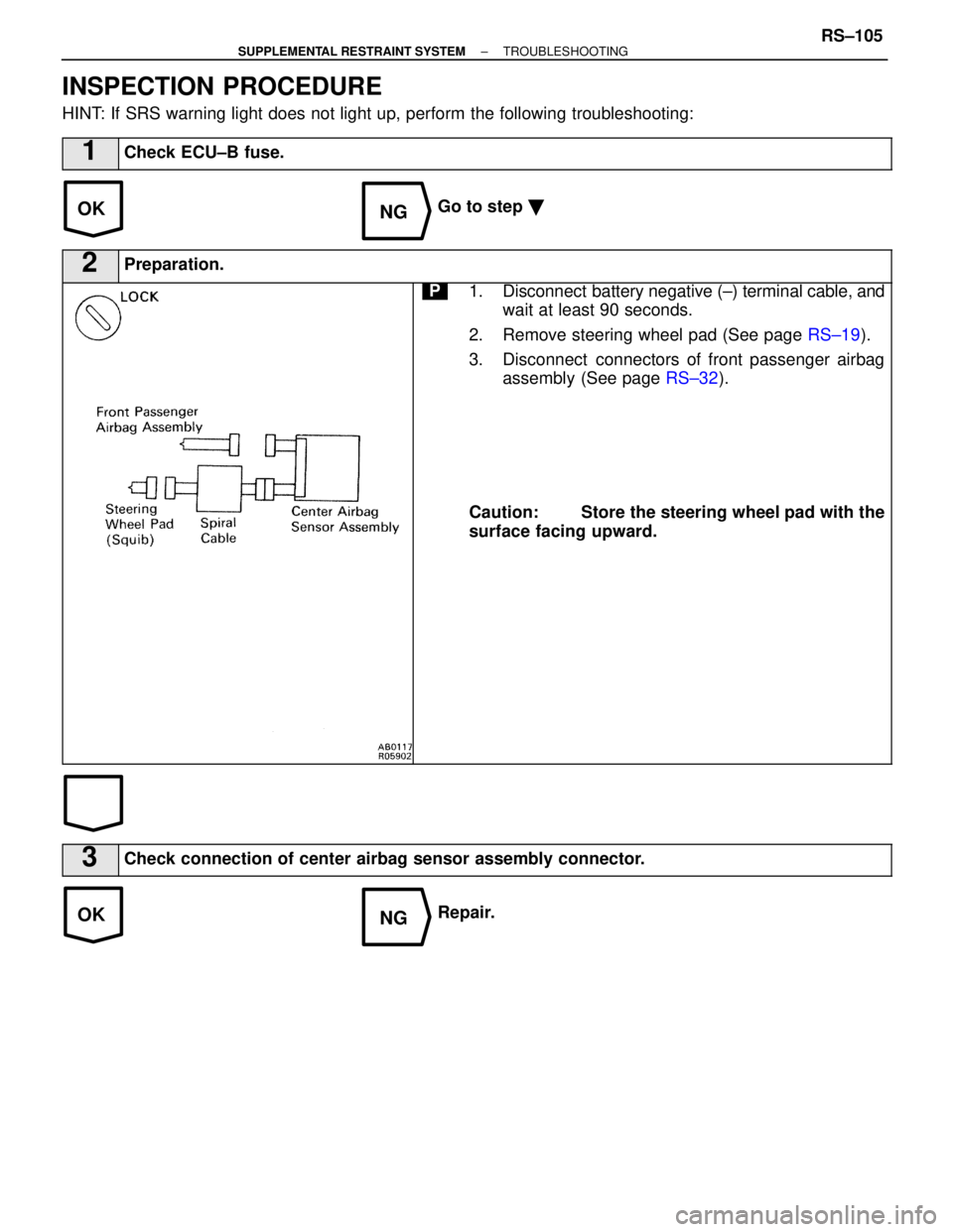
INSPECTION PROCEDURE
HINT: If SRS warning light does not light up, perform the following troublesh\
ooting:
1Check ECU±B fuse.
Go to step �
2Preparation.
P1. Disconnect battery negative (±) terminal cable, and
wait at least 90 seconds.
2. Remove steering wheel pad (See page RS±19).
3. Disconnect connectors of front passenger airbag assembly (See page RS±32).
Caution: Store the steering wheel pad with the
surface facing upward.
3Check connection of center airbag sensor assembly connector.
Repair.
±
SUPPLEMENTAL RESTRAINT SYSTEM TROUBLESHOOTINGRS±105
WhereEverybodyKnowsYourName