Page 3496 of 4087
CIRCUIT DESCRIPTION (Cont'd)
DIAGNOSIS CODE DETECTION DRIVING PATTERN
Purpose of the driving pattern.
(a) To simulate diag. code detecting condition after diag. code is recorded.
(b) To check that the malfunction is corrected when the repair is completed co\
nfirming that diag. codeis no longer detected.
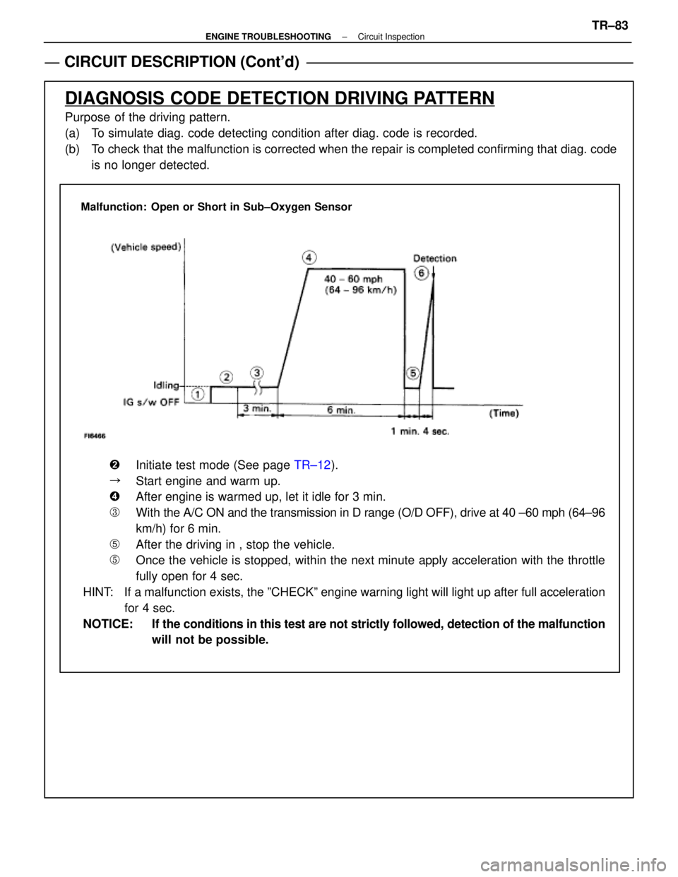
Malfunction: Open or Short in Sub±Oxygen Sensor
�Initiate test mode (See page TR±12).
�Start engine and warm up.
�After engine is warmed up, let it idle for 3 min.
�With the A/C ON and the transmission in D range (O/D OFF), drive at 40 ±\
60 mph (64±96
km/h) for 6 min.
�After the driving in , stop the vehicle.
�Once the vehicle is stopped, within the next minute apply acceleration w\
ith the throttle
fully open for 4 sec.
HINT: If a malfunction exists, the ºCHECKº engine warning light will light\
up after full acceleration for 4 sec.
NOTICE: If the conditions in this test are not strictly followed, detection of the\
malfunction will not be possible.
±
ENGINE TROUBLESHOOTING Circuit InspectionTR±83
WhereEverybodyKnowsYourName
Page 3502 of 4087
Diag. Code 31Air Flow Meter Circuit
CIRCUIT DESCRIPTION
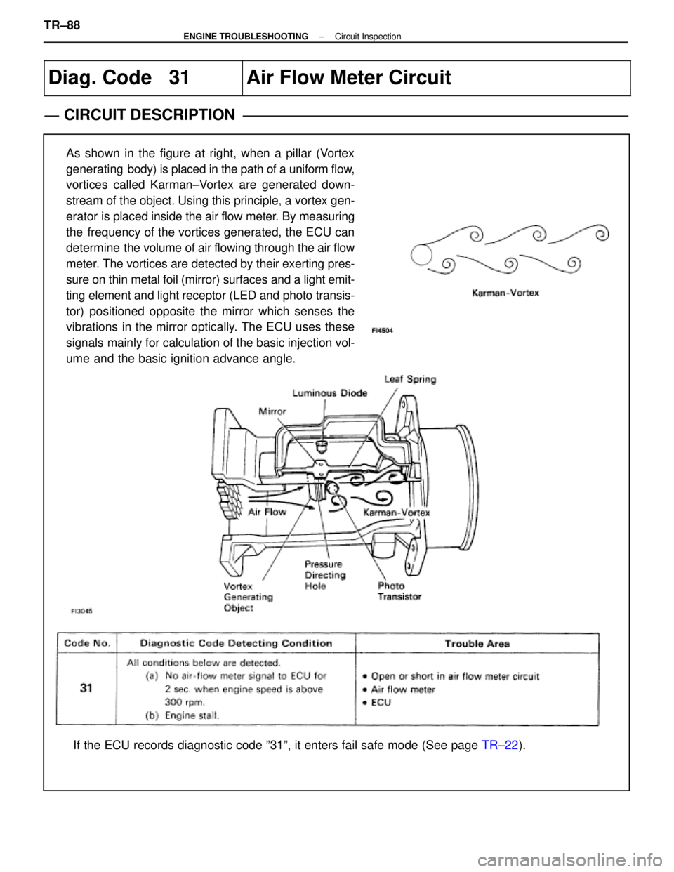
As shown in the figure at right, when a pillar (Vortex
generating body) is placed in the path of a uniform flow,
vortices called Karman±Vortex are generated down-
stream of the object. Using this principle, a vortex gen-
erator is placed inside the air flow meter. By measuring
the frequency of the vortices generated, the ECU can
determine the volume of air flowing through the air flow
meter. The vortices are detected by their exerting pres-
sure on thin metal foil (mirror) surfaces and a light emit-
ting element and light receptor (LED and photo transis-
tor) positioned opposite the mirror which senses the
vibrations in the mirror optically. The ECU uses these
signals mainly for calculation of the basic injection vol-
ume and the basic ignition advance angle.
If the ECU records diagnostic code º31º, it enters fail safe mode \
(See page TR±22).
TR±88
±
ENGINE TROUBLESHOOTING Circuit Inspection
WhereEverybodyKnowsYourName
Page 3513 of 4087
INSPECTION PROCEDURE
Check output condition of diag. code 43
Setting the test mode.
6. Turn ignition switch OFF.
7. Connect terminals TE2 and E1 of TDCL.
8. Turn ignition switch ON.(Don't start the engine)
9. Connect terminals TE1 and E1 of TDCL.
Check if code ª43º is output by the ªCHECKº en-
gine warning light.
Code ª43º is output.
Start the engine.
Check if the code ª43º disappear.
Code ª43º is not output.
Proceed to next circuit inspection shown on
matrix chart (See page
TR±39).
Check for open in harness and connector between engine (& ECT) ECU
and starter relay (See page IN±27)
Repair or replace harness or connector.
Check and replace engine (& ECT) ECU.
±
ENGINE TROUBLESHOOTING Circuit InspectionTR±97
WhereEverybodyKnowsYourName
Page 3517 of 4087
NGOK
OKNG
v
INSPECTION PROCEDURE
1Check output condition of diag. code 43.
C
OK
P
OK
C
Setting the test mode.
(2) Turn ignition switch OFF.
(2) Connect terminals TE2 and E1 of TDCL.
(2) Turn ignition switch ON.(Don't start the engine)
(2) Connect terminals TE1 and E1 of TDCL.
Check if code ª43º is output by the ªCHECKº engine
warning light.
Code ª43º is output.
Start the engine.
Check if the code ª43º disapears.
Code ª43º is not output.
Proceed to next circuit inspection shown on maxtric
chart (See page TR±35).
2Check for open in harness and connectors between engine & ECT ECU and st\
arter relay
(See page IN±27).
Repair or replace harness or connector.
Check and replace engine & ECT ECU.
±
ENGINE TROUBLESHOOTING Circuit InspectionTR±101
WhereEverybodyKnowsYourName
Page 3519 of 4087
CIRCUIT DESCRIPTION (Cont'd)
DIAGNOSIS CODE DETECTION DRIVING PATTERN
Purpose of the driving pattern.
(a) To simulate diag. code detecting condition after diag. code is recorded.
(b) To check that the malfunction is corrected when the repair is completed c\
onfirming that diag. code is nolonger detected.
Malfunction: Open or Short in Knock Sensor
�Start engine and warm up.
�After engine is warmed up, let it idle for 3 min.
�With the A/C ON, perform quick racing (5,000 rpm) three times.
(Rapidly depress the accelerator pedal and suddenly release it.)
HINT: If a malfunction exists, the ºCHECKº engine warning light will lig\
ht up when sudden racing is performed.
NOTICE: If the conditions in this test are not strictly followed, detection of t\
he malfunction will
not be possible.
±
ENGINE TROUBLESHOOTING Circuit InspectionTR±103
WhereEverybodyKnowsYourName
Page 3524 of 4087
Diag. Code 71
EGR System Malfunction (Only for
USA spec.)
CIRCUIT DESCRIPTION
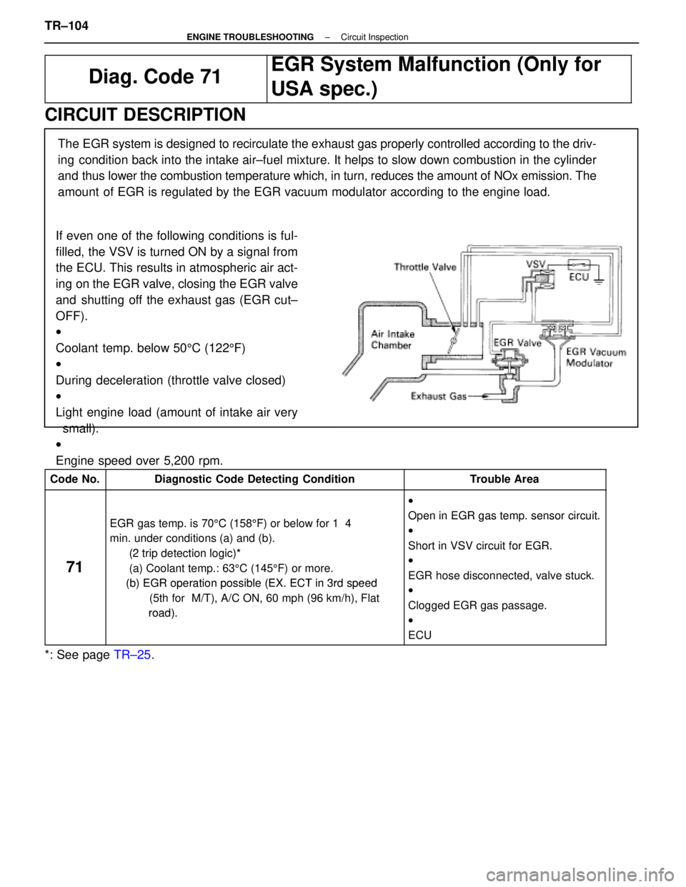
If even one of the following conditions is ful-
filled, the VSV is turned ON by a signal from
the ECU. This results in atmospheric air act-
ing on the EGR valve, closing the EGR valve
and shutting off the exhaust gas (EGR cut±
OFF).
w
Coolant temp. below 505C (122 5F)
w
During deceleration (throttle valve closed)
w
Light engine load (amount of intake air very
small).
w
Engine speed over 5,200 rpm. The EGR system is designed to recirculate the exhaust gas properly controll\
ed according to the driv-
ing condition back into the intake air±fuel mixture. It helps to slow dow\
n combustion in the cylinder
and thus lower the combustion temperature which, in turn, reduces the amoun\
t of NOx emission. The
amount of EGR is regulated by the EGR vacuum modulator according to the engine\
load.
Code No.Diagnostic Code Detecting ConditionTrouble Area
EGR t i 70
5C (158 5F) b l f 1 4
w
Open in EGR
gas temp. sensor circuit.EGR gas temp. is 70 5C (158 5F) or below for 1 4
min. under conditions (a) and (b).
(2 trip detection logic)*
Oen in EGR gas tem. sensor circuit.
w
Short in VSV circuit for EGR.
71
(2 trip detection logic)*
(a) Coolant temp.: 63 5C (145 5F) or more.
(b) EGR operationpossible (EX ECT in 3rd speed
Short in VSV circuit for EGR.
w
EGR hose disconnected, valve stuck.
(b) EGR operation possible (EX. ECT in 3rd speed
(5th for M/T), A/C ON, 60 mph (96 km/h), Flat
road)
EGR hose disconnected, valve stuck.
w
Clogged EGR gas passage.
road).gg g g
w
ECU
*: See page TR±25.
TR±104
±
ENGINE TROUBLESHOOTING Circuit Inspection
WhereEverybodyKnowsYourName
Page 3525 of 4087
CIRCUIT DESCRIPTION (Cont'd)
DIAGNOSIS TROUBLE CODE DETECTION DRIVING PATTERN
Purpose of the driving pattern.
(a) To simulate diag. trouble code detecting condition after diag. trouble co\
de is recorded.
(b) To check that the malfunction is corrected when the repair is completed co\
nfirming that diag. trouble codeis no longer detected.
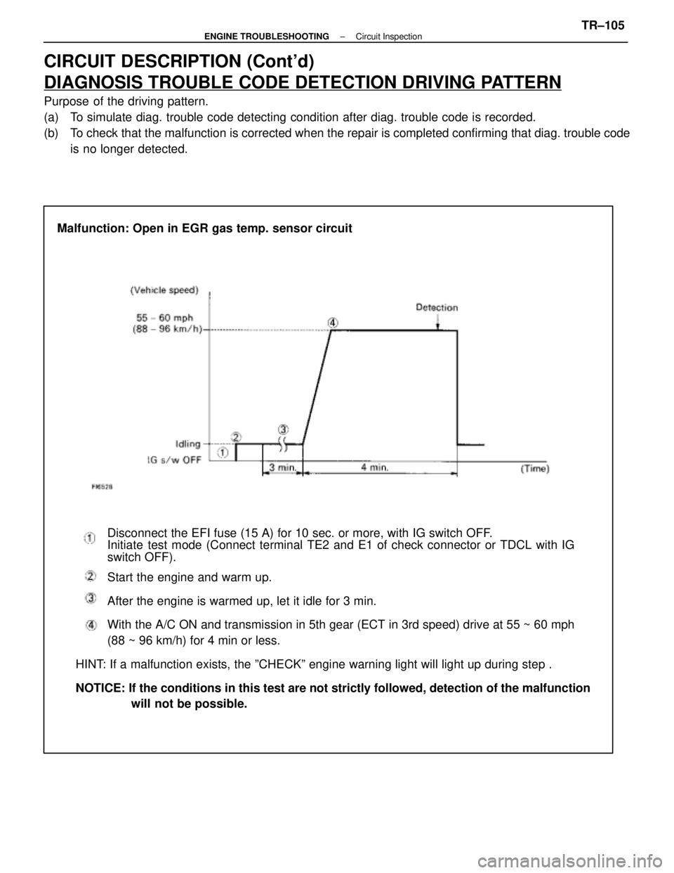
Malfunction: Open in EGR gas temp. sensor circuit
Disconnect the EFI fuse (15 A) for 10 sec. or more, with IG switch OFF\
.
Initiate test mode (Connect terminal TE2 and E1 of check connector or TDCL with\
IG
switch OFF).
Start the engine and warm up.
After the engine is warmed up, let it idle for 3 min.
With the A/C ON and transmission in 5th gear (ECT in 3rd speed) drive at 5\
5 ~ 60 mph
(88 ~ 96 km/h) for 4 min or less.
HINT: If a malfunction exists, the ºCHECKº engine warning light will l\
ight up during step .
NOTICE: If the conditions in this test are not strictly followed, detection of \
the malfunction will not be possible.
±
ENGINE TROUBLESHOOTING Circuit InspectionTR±105
WhereEverybodyKnowsYourName
Page 3530 of 4087
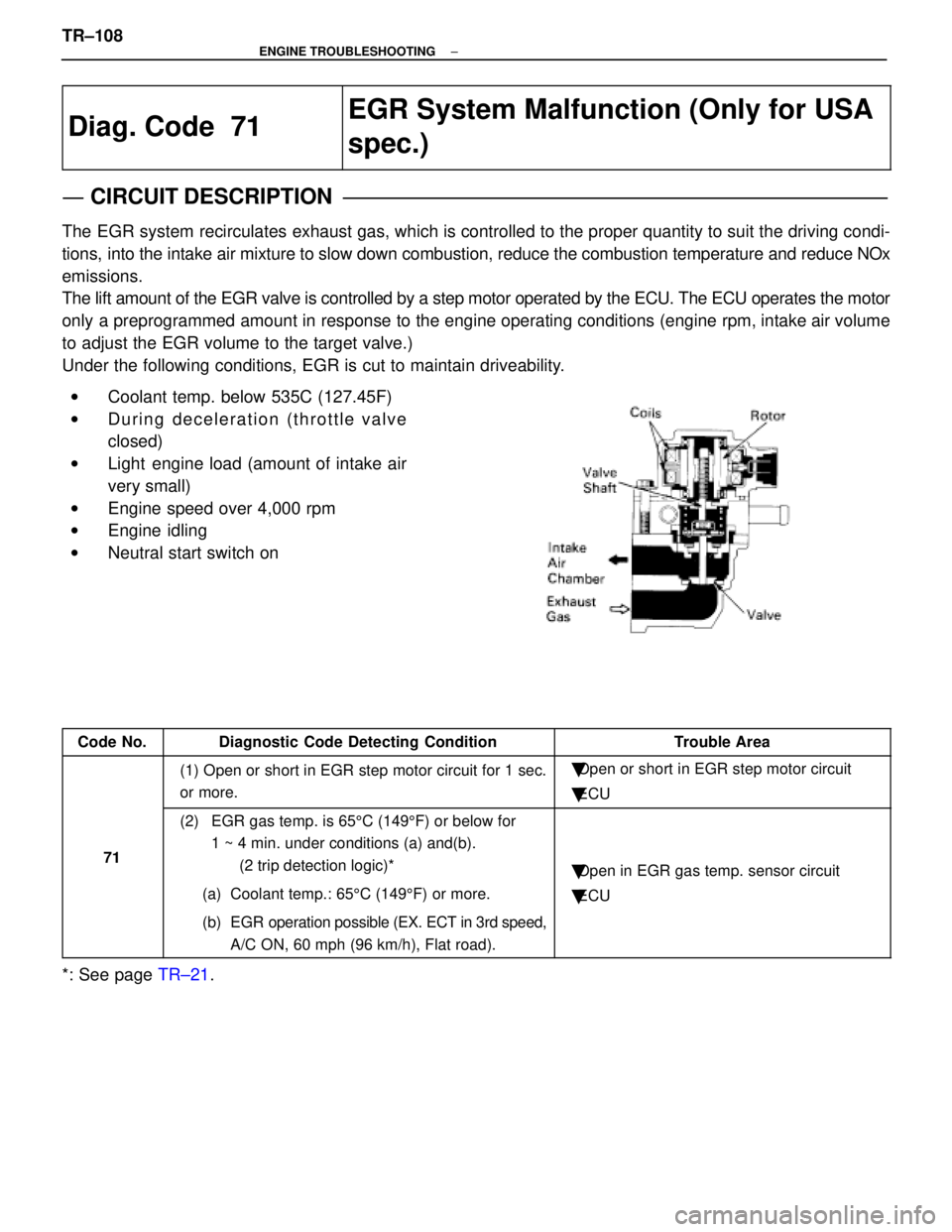
Diag. Code 71
EGR System Malfunction (Only for USA
spec.)
CIRCUIT DESCRIPTION
The EGR system recirculates exhaust gas, which is controlled to the proper quantity to suit the driv\
ing condi-
tions, into the intake air mixture to slow down combustion, reduce the combust\
ion temperature and reduce NOx
emissions.
The lift amount of the EGR valve is controlled by a step motor operated \
by the ECU. The ECU operates the motor
only a preprogrammed amount in response to the engine operating conditions (\
engine rpm, intake air volume
to adjust the EGR volume to the target valve.)
Under the following conditions, EGR is cut to maintain driveability.
wCoolant temp. below 535C (127.45F)
w During deceleration (throttle valve
closed)
w Light engine load (amount of intake air
very small)
w Engine speed over 4,000 rpm
w Engine idling
w Neutral start switch on
Code No.Diagnostic Code Detecting ConditionTrouble Area
(1) Open or short in EGR step motor circuit for 1 sec.
or more.�Open or short in EGR step motor circuit
� ECU
71
(2) EGR gas temp. is 65 5C (149 5F) or below for
1 ~ 4 min. under conditions (a) and(b).
(2 trip detection logic)*
(a) Coolant temp.: 65 5C (149 5F) or more.
(b) EGR operation possible (EX. ECT in 3rd speed, A/C ON, 60 mph (96 km/h), Flat road).
�Open in EGR gas temp. sensor circuit
� ECU
*: See page TR±21.
TR±108
±
ENGINE TROUBLESHOOTING
WhereEverybodyKnowsYourName