Page 3291 of 4087
FRONT SHOCK ABSORBER REMOVAL
SA0RN±04
1. JACK UP VEHICLE AND REMOVE FRONT WHEEL
2. REMOVE BRAKE CALIPER
(a) Remove the 2 bolts and caliper from the steering knuckle.
(b) Hang up the brake caliper using wire, etc.
3. REMOVE FRONT FENDER SPLUSH SHIELD
4. LH side only:MOVE WASHER TANK
(a) Remove the bolt.
(b) Remove the bolt and move the washer tank away from the body.
5. DISCONNECT ABS SPEED SENSOR AND WIRE HARNESS
(a) Remove the bolt and disconnect the speed sensor from the
steering knuckle.
SA±28
±
SUSPENSION AND AXLE FRONT SUSPENSION
WhereEverybodyKnowsYourName
Page 3297 of 4087

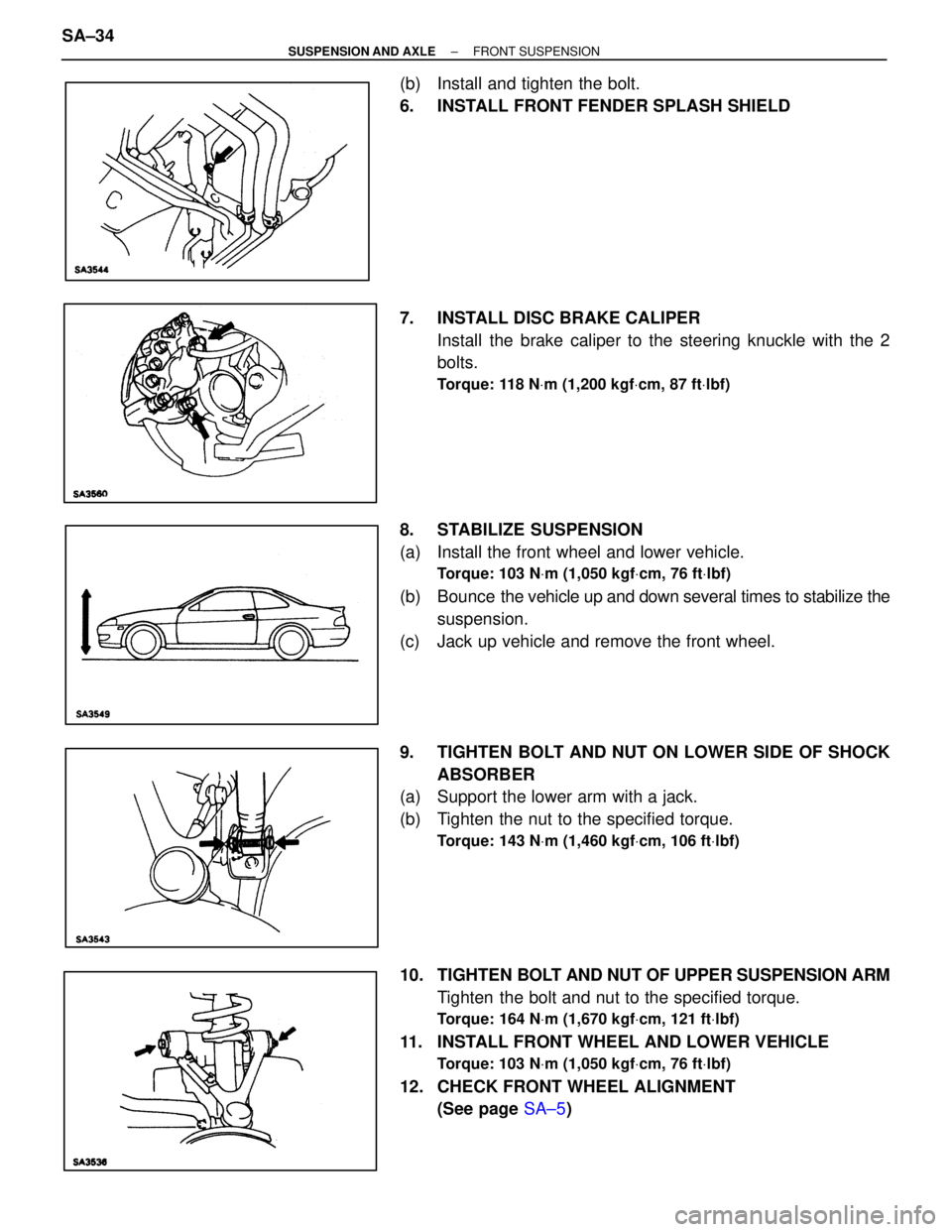
(b) Install and tighten the bolt.
6. INSTALL FRONT FENDER SPLASH SHIELD
7. INSTALL DISC BRAKE CALIPERInstall the brake caliper to the steering knuckle with the 2
bolts.
Torque: 118 N Vm (1,200 kgf Vcm, 87 ft Vlbf)
8. STABILIZE SUSPENSION
(a) Install the front wheel and lower vehicle.
Torque: 103 N Vm (1,050 kgf Vcm, 76 ft Vlbf)
(b) Bounce the vehicle up and down several times to stabilize the
suspension.
(c) Jack up vehicle and remove the front wheel.
9. TIGHTEN BOLT AND NUT ON LOWER SIDE OF SHOCK ABSORBER
(a) Support the lower arm with a jack.
(b) Tighten the nut to the specified torque.
Torque: 143 N Vm (1,460 kgf Vcm, 106 ft Vlbf)
10. TIGHTEN BOLT AND NUT OF UPPER SUSPENSION ARM
Tighten the bolt and nut to the specified torque.
Torque: 164 N Vm (1,670 kgf Vcm, 121 ft Vlbf)
11. INSTALL FRONT WHEEL AND LOWER VEHICLE
Torque: 103 N Vm (1,050 kgf Vcm, 76 ft Vlbf)
12. CHECK FRONT WHEEL ALIGNMENT
(See page SA±5)
SA±34
±
SUSPENSION AND AXLE FRONT SUSPENSION
WhereEverybodyKnowsYourName
Page 3299 of 4087
UPPER SUSPENSION ARM REMOVAL
SA1A2±01
1. JACK UP VEHICLE AND REMOVE FRONT WHEEL
2. REMOVE FRONT BRAKE CALIPER AND DISC
(a) Remove the 2 bolts and brake caliper from the steeringknuckle.
(b) Hang up the caliper using wire, etc.
3. REMOVE FRONT FENDER SPLASH SHIELD
4. LH side only: MOVE WASHER TANK
(a) Loosen the bolt.
(b) Remove the bolt and move the washer tank away from the body.
5. REMOVE ABS SPEED SENSOR AND WIRE HARNESS CLAMP
(a) Remove the bolt and disconnect the speed sensor from the
steering knuckle.
SA±36
±
SUSPENSION AND AXLE FRONT SUSPENSION
WhereEverybodyKnowsYourName
Page 3302 of 4087
(b) Install and tighten the bolt.
4. INSTALL FRONT FENDER SPLASH SHEILD
5. INSTALL BRAKE CALIPERInstall the brake caliper to the steering knuckle with the 2
bolts.
Torque: 118 N Vm (1,200 kgf Vcm, 87 ft Vlbf)
6. STABILIZE SUSPENSION
(a) Install the front wheel.
Torque: 103 N Vm (1,050 kgf Vcm, 76 ft Vlbf)
(b) Bounce the vehicle up and down several times to stabilize the
suspension.
(c) Jack up the vehicle and remove the front wheel.
7. TIGHTEN BOLT AND NUT OF UPPER SUSPENSION ARM
(a) Support the lower arm with jack.
(b) Torque the bolt and nut the specified torque.
Torque: 164 N Vm (1,670 kgf Vcm, 121 ft Vlbf)
8. INSTALL FRONT WHEEL AND LOWER VEHICLE
Torque: 103 N Vm (1,050 kgf Vcm, 76 ft Vlbf)
9. CHECK FRONT WHEEL ALIGNMENT
(See page SA±5)
±
SUSPENSION AND AXLE FRONT SUSPENSIONSA±39
WhereEverybodyKnowsYourName
Page 3307 of 4087
3. INSTALL BRAKE CALIPERInstall the brake caliper to the steering cnuckle with the 2
bolts.
Torque: 118 N Vm (1,200 kgf Vcm, 87 ft Vlbf)
4. STABILIZE SUSPENSION
(a) Install the front wheel and jack down the vehicle.
Torque: 103 N Vm (1,050 kgf Vcm, 76 ft Vlbf)
(b) Bounce the vehicle up and down several times to stabilize the
suspension.
5. TORQUE ADJUSTING CAMS AND NUTS
(a) Jack up the vehicle and remove the front wheel.
(b) Support the lower arm with jack.
(c) Align the matchmarks and torque the adjusting cams and nuts with the vehicle weight on the suspension.
Torque: 226 N Vm (2,300 kgf Vcm, 166 ft Vlbf)
6. INSTALL ENGINE UNDER COVER
7. INSTALL FRONT WHEEL
Torque: 103 N Vm (1,050 kgf Vcm, 76 ft Vlbf)
8. CHECK FRONT WHEEL ALIGNMENT
(See page SA±5)
SA±44
±
SUSPENSION AND AXLE FRONT SUSPENSION
WhereEverybodyKnowsYourName
Page 3309 of 4087

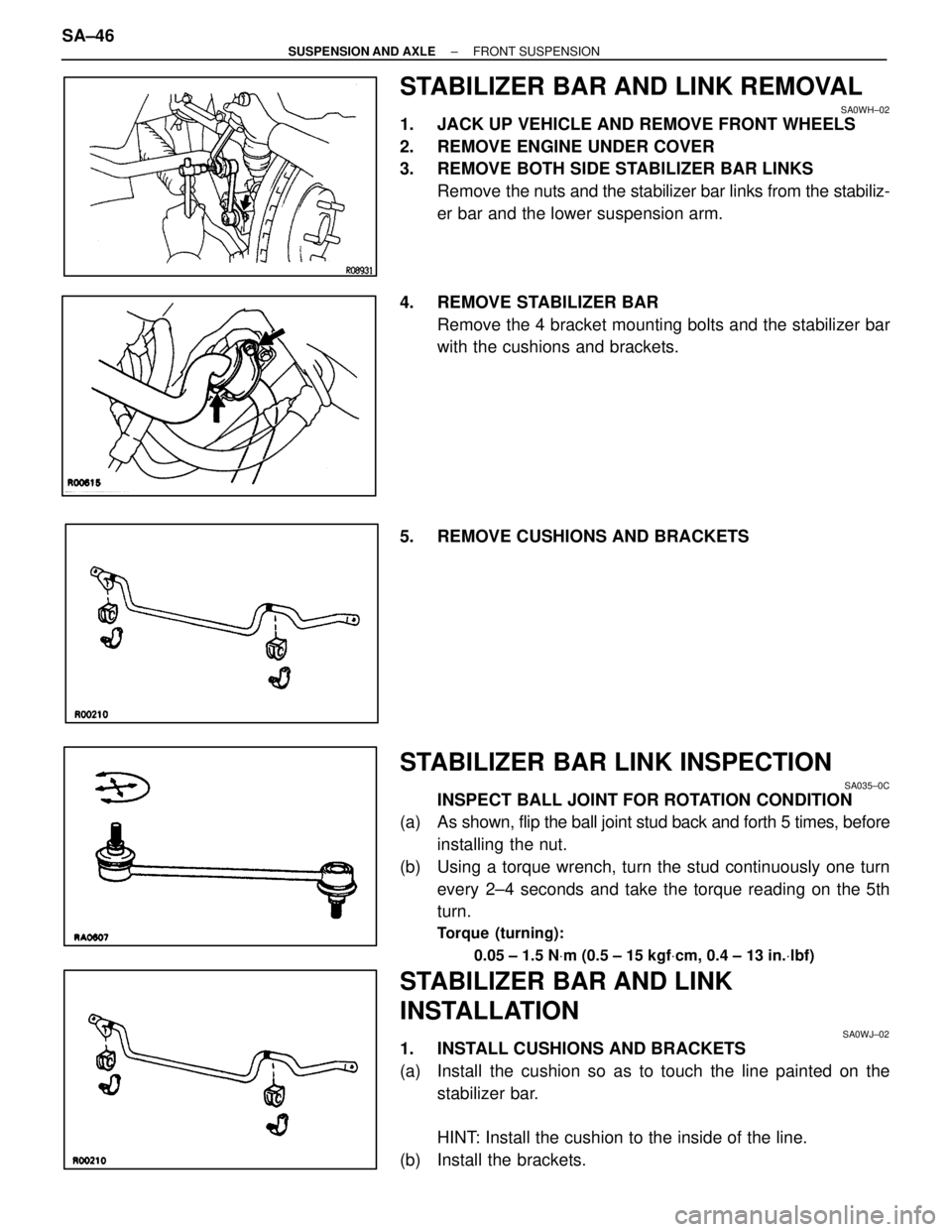
STABILIZER BAR AND LINK REMOVAL
SA0WH±02
1. JACK UP VEHICLE AND REMOVE FRONT WHEELS
2. REMOVE ENGINE UNDER COVER
3. REMOVE BOTH SIDE STABILIZER BAR LINKSRemove the nuts and the stabilizer bar links from the stabiliz-
er bar and the lower suspension arm.
4. REMOVE STABILIZER BAR Remove the 4 bracket mounting bolts and the stabilizer bar
with the cushions and brackets.
5. REMOVE CUSHIONS AND BRACKETS
STABILIZER BAR LINK INSPECTION
SA035±0C
INSPECT BALL JOINT FOR ROTATION CONDITION
(a) As shown, flip the ball joint stud back and forth 5 times, before
installing the nut.
(b) Using a torque wrench, turn the stud continuously one turn every 2±4 seconds and take the torque reading on the 5th
turn.
Torque (turning):
0.05 ± 1.5 N Vm (0.5 ± 15 kgf Vcm, 0.4 ± 13 in. Vlbf)
STABILIZER BAR AND LINK
INSTALLATION
SA0WJ±02
1. INSTALL CUSHIONS AND BRACKETS
(a) Install the cushion so as to touch the line painted on the
stabilizer bar.
HINT: Install the cushion to the inside of the line.
(b) Install the brackets.
SA±46
±
SUSPENSION AND AXLE FRONT SUSPENSION
WhereEverybodyKnowsYourName
Page 3310 of 4087
2. INSTALL STABILIZER BARInstall the stabilizer bar to the body with the bolts.
Torque: 18 N Vm (180 kgf Vcm, 13 ft Vlbf)
3. INSTALL BOTH SIDE STABILIZER BAR LINKS
Install the stabilizer bar links to the stabilizer bar and the low-
er suspension arm with the nuts.
Torque: 74 N Vm (750 kgf Vcm, 54 ft Vlbf)
4. REMOVE ENGINE UNDER COVER
5. INSTALL FRONT WHEEL AND LOWER VEHICLE
Torque: 103 N Vm (1,050 kgf Vcm, 76 ft Vlbf)
±
SUSPENSION AND AXLE FRONT SUSPENSIONSA±47
WhereEverybodyKnowsYourName
Page 3315 of 4087
REAR AXLE CARRIER REMOVAL
SA0RY±03
1. JACK UP VEHICLE AND REMOVE REAR WHEEL
2. REMOVE REAR BRAKE CALIPER AND BRAKE DISC
(a) Remove the 2 bolts and remove the brake caliper from therear axle hub.
(b) Hang up the brake caliper using wire, etc.
(c) Place matchmarks on the brake disc and axle hub.
(d) Remove the brake disc.
3. CHECK BACKLASH IN BEARING SHAFT DIRECTION Place the dial indicator near the center of the axle hub and
check the backlash in the bearing shaft direction.
Maximum:
0.05 mm (0.0020 in.)
If greater than the specified maximum, replace the bearing.
4. CHECK AXLE HUB DEVIATION Using a dial indicator, check the deviation at the surface of
the axle hub outside the hub bolt.
Maximum:
0.07 mm (0.0028 in.)
If greater than the specified maximum, replace the axle hub.
SA±52
±
SUSPENSION AND AXLE REAR AXLE HUB
WhereEverybodyKnowsYourName