Page 201 of 4087
1
(1) Turn ignition switch LOCK.
(2) Disconnect negative (±) terminal cable frombattery.
(3) Disconnect center airbag sensor assembly connector.
(4) Connect negative (±) terminal cable to battery.
Does airbag warning light turn off?
Check airbag warning light circuit or terminal
AB circuit of TDCL or check connector.NG
YES
Check operation of airbag warning light.
Replace center airbag sensor assembly.
INSPECTION PROCEDURE
±
SRS AIRBAG TroubleshootingAB±85
WhereEverybodyKnowsYourName
Page 202 of 4087

NG
Check voltage between terminals Tc and E
1of TDCL or check connector.
OK1
2
3
1
NG
NG
NG OK
OK
OK
3
Check voltage between terminal Tc of TDCL
or check connector and body ground.Check center airbag sensor assembly.
Replace center airbag sensor assemly.
Check resistance between terminal Tc of
center airbag sensor assembly and body
ground.
HINT: If the diagnostic code is continuously displayed, perform the following \
troubleshooting:
Repair or replace harnes or connector. Replace center airbag sensor
assembly.
Check harness between center
airbag sensor assembly and
TDCL or check connector.
Check harness between terminal
E1 of TDCL or check connector
and body ground.
Go to step
Tc Terminal Circuit
CIRCUIT DESCRIPTION
By connecting terminals Tc and E of the TDCL or check connector, the center airbag sensor assembly
is set in the diagnostic code output mode. The diagnostic codes are disp\
layed by the blinking of the
airbag warning light.
DIAGNOSTIC CHART
Troubleshooting
for this system is dif ferent depending on whether the diagnostic code is not displayed
or is continuously displayed. Confirm the problem symptoms first before se\
lecting the appropriate
troubleshooting procedure.
HINT: If the diagnostic code is not displayed, perform the following trouble\
shooting:
AB±86
±
SRS AIRBAG Troubleshooting
WhereEverybodyKnowsYourName
Page 205 of 4087
NGOK
Check center airbag sensor assembly.3
(1) Disconnect negative (±) terminal cable from
battery, and wait at least 20 seconds.
(2) Turn ignition switch lock.
(3) Disconnect center airbag sensor assembly
connector.
(4) Using a service wire, connector terminal Tc of center airbag sensor assembly connector to
body ground.
(5) Install the center airbag sensor assembly.
(6) Connect negative (±) terminal cable to battery.
(7) Turn ignition switch ACC or ON.
Check operation of airbag warning light.
Airbag light comes on.
Check harness between center airbag sensor
assembly and TDCL or check connector.
Replace center airbag sensor assembly.
C
P
OK
CautionNever turn ignition switch ACC or ON and
never connect negative (±) terminal to battery
before the center airbag sensor assembly is
installed.
±
SRS AIRBAG TroubleshootingAB±89
WhereEverybodyKnowsYourName
Page 208 of 4087

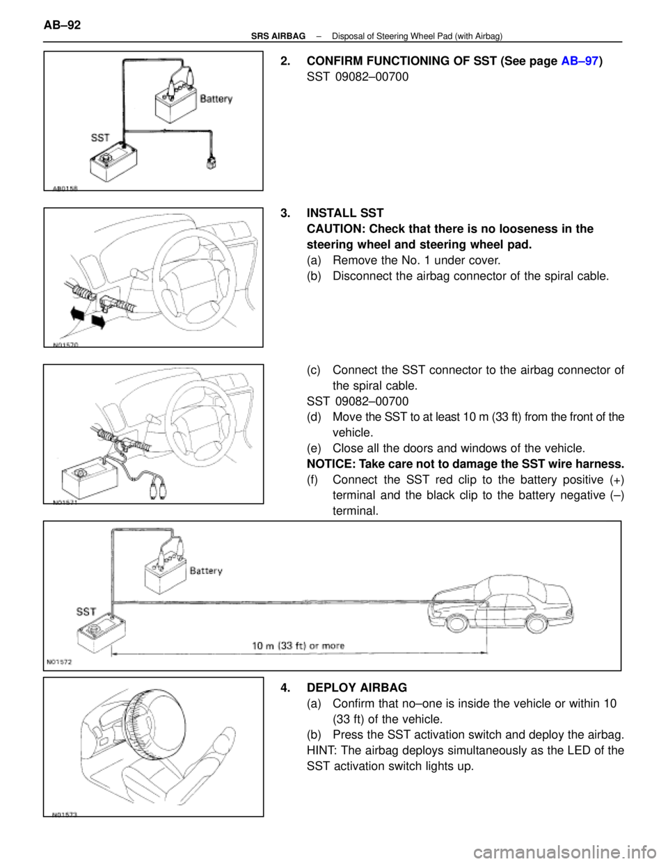
2. CONFIRM FUNCTIONING OF SST (See page AB±97)
SST 09082±00700
3. INSTALL SST CAUTION: Check that there is no looseness in the
steering wheel and steering wheel pad.
(a) Remove the No. 1 under cover.
(b) Disconnect the airbag connector of the spiral cable.
(c) Connect the SST connector to the airbag connector ofthe spiral cable.
SST 09082±00700
(d) Move the SST to at least 10 m (33 ft) from the front of the
vehicle.
(e) Close all the doors and windows of the vehicle.
NOTICE: Take care not to damage the SST wire harness.
(f) Connect the SST red clip to the battery positive (+) terminal and the black clip to the battery negative (±)
terminal.
4. DEPLOY AIRBAG (a) Confirm that no±one is inside the vehicle or within 10 (33 ft) of the vehicle.
(b) Press the SST activation switch and deploy the airbag.
HINT: The airbag deploys simultaneously as the LED of the
SST activation switch lights up.
AB±92
±
SRS AIRBAG Disposal of Steering Wheel Pad (with Airbag)
WhereEverybodyKnowsYourName
Page 212 of 4087

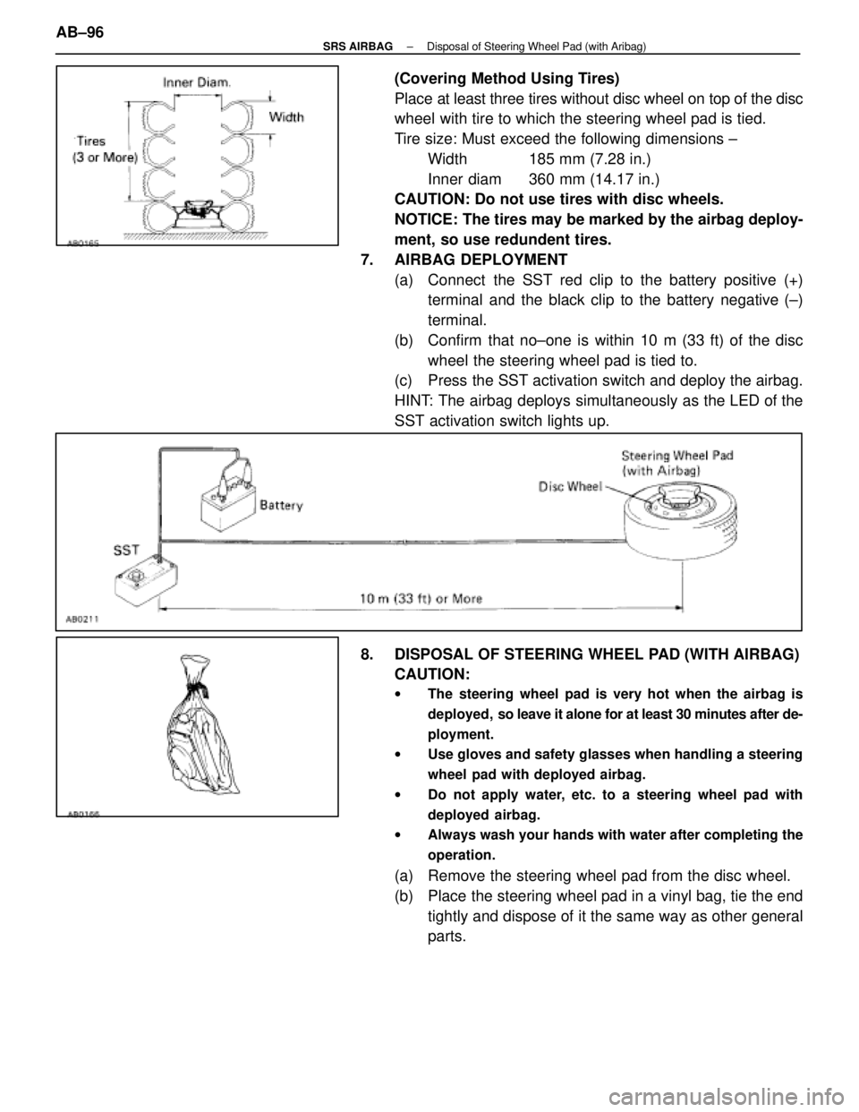
(Covering Method Using Tires)
Place at least three tires without disc wheel on top of the disc
wheel with tire to which the steering wheel pad is tied.
Tire size: Must exceed the following dimensions ±Width 185 mm (7.28 in.)
Inner diam 360 mm (14.17 in.)
CAUTION: Do not use tires with disc wheels.
NOTICE: The tires may be marked by the airbag deploy-
ment, so use redundent tires.
7. AIRBAG DEPLOYMENT (a) Connect the SST red clip to the battery positive (+)terminal and the black clip to the battery negative (±)
terminal.
(b) Confirm that no±one is within 10 m (33 ft) of the disc wheel the steering wheel pad is tied to.
(c) Press the SST activation switch and deploy the airbag.
HINT: The airbag deploys simultaneously as the LED of the
SST activation switch lights up.
8. DISPOSAL OF STEERING WHEEL PAD (WITH AIRBAG) CAUTION:
w The steering wheel pad is very hot when the airbag is
deployed, so leave it alone for at least 30 minutes after de-
ployment.
w Use gloves and safety glasses when handling a steering
wheel pad with deployed airbag.
w Do not apply water, etc. to a steering wheel pad with
deployed airbag.
w Always wash your hands with water after completing the
operation.
(a) Remove the steering wheel pad from the disc wheel.
(b) Place the steering wheel pad in a vinyl bag, tie the end
tightly and dispose of it the same way as other general
parts.
AB±96
±
SRS AIRBAG Disposal of Steering Wheel Pad (with Aribag)
WhereEverybodyKnowsYourName
Page 213 of 4087
CONFIRM FUNCTIONING OF SST
When deploying the airbag, always use the specified SST:
SRS AIRBAG DEPLOYMENT TOOL.
SST 09082±00700
1. CONNECT SST TO BATTERY Connect the red clip of the SST to the battery positive (+) ter-
minal and the black clip to the battery negative (±) terminal.
HINT: Do not connect the yellow connector which connects
with the airbag system.
2. CONFIRM FUNCTIONING OF SST Press the SST activation switch, and confirm the LED of the
SST activation switch lights up.
CAUTION: If the LED lights up when the activation switch
is not being pressed, SST malfunction is probable, so
definitely do not use the SST.
±
SRS AIRBAG Disposal of Steering Wheel Pad (with Aribag)AB±97
WhereEverybodyKnowsYourName
Page 216 of 4087

GENERAL DESCRIPTION
The LEXUS SC400 is equipped with an SRS (Supplemental Restraint System) a\
irbag.
Failure to carry out service operations in the correct sequence could cause the\
airbag system to unex-
pectedly deploy during servicing, possibly leading to a serious accident.
Further, if a mistake is made in servicing the airbag system, it is possible the\
airbag may fail to operate
when required.
Before performing servicing (including removal or installation of parts, insp\
ection or replacement), be
sure to read the following items carefully, then follow the correct procedure described in the repair
manual.
1. Malfunction symptoms of the airbag system are difficult to confirm, so the diagnostic codes become themost important source of information when troubleshooting.
When troubleshooting the airbag system, always inspect the diagnostic co\
des before disconnecting the
battery (See page AB±25).
2. Work must be started after approx. 20 seconds or longer from the time the ig\
nition switch is turned to the LOCK position and the negative (±) terminal cable is disconnec\
ted from the battery. (The
airbag system is equipped with a back±up power source so that if work is sta\
rted within 20 seconds
of disconnecting the negative (±) terminal cable of the battery, the airbag may be deployed.)
When the negative (±) terminal cable is disconnected from the battery, memory of the clock and audio sys-
tems will be cancelled. So before starting work, make a record of the conten\
ts memorized by the audio
memory system. Then when work is finished, reset the audio systems as before a\
nd adjust the clock. When
the vehicle has power tilt and power telescopic steering, power seat, power \
outside rear view mirror and
power shoulder belt anchorage, which are all equipped with memory function, it\
is not possible to make
a record of the memory contents. So when the work is finished, it will be\
necessary to explain this fact to
the customer, and ask the customer to adjust the features and reset the memory. To avoid erasing the
memory of each memory system, never use a back±up power supply from outside\
the vehicle.
3. Even in cases of a minor collision where the airbag does not deploy, the front airbag sensors and
the steering wheel pad should be inspected (See page AB±9).
4. Never use airbag parts from another vehicle. When replacing parts, replace them with new parts.
5. Before repairs, remove the airbag sensors if shocks are likely to be applied to the sensors during repairs.
6. Never disassemble and repair the front airbag sensors, center airbag sensor a\
ssembly or steering
wheel pad in order to reuse it.
7. If the front airbag sensors, center airbag assembly or steering wheel pa\
d have been dropped, or if there are cracks, dents or other defects in the case, bracket or conn\
ector, replace them with new
ones.
8. Do not expose the front airbag sensors, center airbag sensor assembly or\
steering wheel pad directly to hot air or flames.
9. Use a volt/ohmmeter with high impedance (10 kW/V minimum) for troubleshoo\
ting of the electrical circuit.
10. Information labels are attached to the periphery of the airbag components. Follow t\
he instructions
on the notices.
11. After work on the airbag system is completed, perform the airbag warning\
light check (See page AB±30 ).
AB±2
SRS AIRBAG
± General Description
WhereEverybodyKnowsYourName
Page 219 of 4087

OPERATION
FUNCTION OF COMPONENTS
1. FRONT AIRBAG SENSORA front airbag sensor is mounted inside each of the front
fenders. The sensor unit is a mechanical type. When the sen-
sor detects deceleration force above a predetermined limit in
a collision, the contacts in the sensor make contact, sending
a signal to the center airbag sensor assembly. The sensor
cannot be disassembled.
2. SPIRAL CABLE (in COMBINATION SWITCH) A spiral cable is used as an electrical joint from the vehicle
body side to the steering wheel.
3. STEERING WHEEL PAD (with AIRBAG) The inflater and bag of the airbag system are stored in the
steering wheel pad and cannot be disassembled.
The inflater contains a squib, igniter charge, gas generant,
etc., and inflates the bag in case of a frontal collision.
4. AIRBAG WARNING LIGHT The airbag warning light is located on the combination meter.
It goes on to alert the driver of trouble in the system when a
malfunction is detected in the center airbag sensor assembly
self±diagnosis. In normal operating condition when the igni-
tion switch is turned to the ACC or ON position, the light goes
on for about 6 seconds and then goes off.
5. CENTER AIRBAG SENSOR ASSEMBLY The center airbag sensor assembly is mounted on the floor
inside the center cluster. The center airbag sensor assembly
consists of a center airbag sensor, safing sensors, ignition
control and drive circuit, diagnosis circuit, etc. It receives sig-
nals f rom the airbag sensors, judges whether the airbag must
be activated or not and diagnoses system malfunctions. AB±5
± OperationSRS AIRBAG
WhereEverybodyKnowsYourName