Page 1289 of 4087

REMOVAL OF HYDRAULIC PUMP
(See Components on page CO±26)
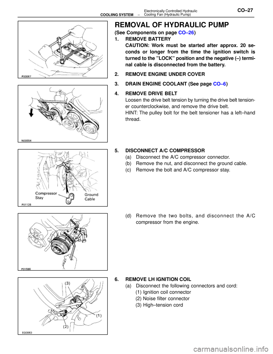
1. REMOVE BATTERY CAUTION: Work must be started after approx. 20 se-
conds or longer from the time the ignition switch is
turned to the ºLOCKº position and the negative (±) termi-
nal cable is disconnected from the battery.
2. REMOVE ENGINE UNDER COVER
3. DRAIN ENGINE COOLANT (See page CO±6)
4. REMOVE DRIVE BELT Loosen the drive belt tension by turning the drive belt tension-
er counterclockwise, and remove the drive belt.
HINT: The pulley bolt for the belt tensioner has a left±hand
thread.
5. DISCONNECT A/C COMPRESSOR (a) Disconnect the A/C compressor connector.
(b) Remove the nut, and disconnect the ground cable.
(c) Remove the bolt and A/C compressor stay.
(d) R e m o v e t h e t w o b o l t s , a n d d i s c onnect the A/C
compressor from the engine.
6. REMOVE LH IGNITION COIL (a) Disconnect the following connectors and cord:(1) Ignition coil connector
(2) Noise filter connector
(3) High±tension cord
±
COOLIING SYSTEM Electronically Controlled Hydraulic
Cooling Fan (Hydraulic Pump)CO±27
WhereEverybodyKnowsYourName
Page 1308 of 4087
18. INSTALL BATTERY
19. FILL ENGINE WITH COOLANT (See page CO±7)
20. FILL COOLING FAN RESERVOIR TANK WITH FLUID (See pages CO±23 and 24)
21. START ENGINE AND CHECK FOR LEAKS
22. INSTALL ENGINE UNDER COVER
CO±46
±
COOLIING SYSTEM Electronically Controlled Hydraulic Cooling Fan
(Hydraulic Pump)
WhereEverybodyKnowsYourName
Page 1310 of 4087
REMOVAL OF HYDRAULIC MOTOR
(See Components on page CO±47)
1. REMOVE BATTERY CAUTION: Work must be started after approx. 20 se-
conds or longer from the time the ignition switch is
turned to the ºLOCKº position and the negative (±) termi-
nal cable is disconnected from the battery.
2. REMOVE ENGINE UNDER COVERS
3. DRAIN ENGINE COOLANT (See page CO±6)
4. REMOVE RADIATOR RESERVOIR TANK (a) Disconnect the coolant level sensor connector.
(b) Disconnect the following hoses:(1) Reservoir hose from water inlet housing
(2) Reservoir hose from radiator
(c) Remove the two bolts and reservoir tank bracket.
(d) Disconnect the reservoir tank from the reservoir tank bracket, and remove the reservoir tank.
5. DISCONNECT HOSES Disconnect the following hoses:(1) Upper radiator hose from radiator
(2) Pressure hose from hydraulic motor
(3) Return hose from hydraulic motor
CO±48
±
COOLIING SYSTEM Electronically Controlled Hydraulic Cooling Fan
(Hydraulic Motor)
WhereEverybodyKnowsYourName
Page 1319 of 4087
7. INSTALL RADIATOR RESERVOIR TANK(a) Install the reservoir tank to the reservoir tank bracket.
(b) Install the reservoir tank bracket with two bolts.
Torque: 4.9 N Vm (50 kgf Vcm, 43 in. Vlbf)
(c) Connect the following hoses:
(1) Reservoir hose to water inlet housing
(2) Reservoir hose to radiator
(d) Connect the coolant level sensor connector.
8. INSTALL BATTERY
9. FILL ENGINE WITH COOLANT (See page CO±7)
10. FILL COOLING FAN RESERVOIR TANK WITH FLUID
(See pages CO±23 and 24)
11. START ENGINE AND CHECK FOR LEAKS
12. INSTALL ENGINE UNDER COVER
±
COOLIING SYSTEM Electronically Controlled Hydraulic Cooling Fan
(Hydraulic Motor)CO±57
WhereEverybodyKnowsYourName
Page 1323 of 4087

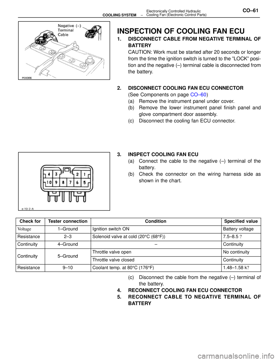
INSPECTION OF COOLING FAN ECU
1. DISCONNECT CABLE FROM NEGATIVE TERMINAL OFBATTERY
CAUTION: Work must be started after 20 seconds or longer
from the time the ignition switch is turned to the ºLOCKº posi-
tion and the negative (±) terminal cable is disconnected from
the battery.
2. DISCONNECT COOLING FAN ECU CONNECTOR (See Components on page CO±60)
(a) Remove the instrument panel under cover.
(b) Remove the lower instrument panel finish panel and glove compartment door assembly.
(c) Disconnect the cooling fan ECU connector.
3. INSPECT COOLING FAN ECU (a) Connect the cable to the negative (±) terminal of thebattery.
(b) Check the connector on the wiring harness side as shown in the chart.
Check forTester connectionConditionSpecified value
Voltage1±GroundIgnition switch ONBattery voltage
Resistance2±3Solenoid valve at cold (20 5C (68 5F))7.5±8.5 �
Continuity4±Ground±Continuity
Continuity5±GroundThrottle valve openNo continuityContinuity5±GroundThrottle valve closedContinuity
Resistance9±10Coolant temp. at 80 5C (176 5F)1.48±1.58 k �
(c) Disconnect the cable from the negative (±) terminal of
the battery.
4. RECONNECT COOLING FAN ECU CONNECTOR
5. RECONNECT CABLE TO NEGATIVE TERMINAL OF BATTERY
±
COOLIING SYSTEM Electronically Controlled Hydraulic
Cooling Fan (Electronic Control Parts)CO±61
WhereEverybodyKnowsYourName
Page 1324 of 4087
(Water Temperature Sensor)
COMPONENTS FOR REMOVAL AND
INSTALLATION
INSPECTION OF WATER TEMPERATURE
SENSOR
1. DISCONNECT CABLE FROM NEGATIVE TERMINAL OFBATTERY
CAUTION: Work must be started after 20 seconds or
longer from the time the ignition switch is turned to the
ºLOCKº position and the negative (±) terminal cable is
disconnected from the battery.
2. REMOVE ENGINE UNDER COVER
3. DRAIN ENGINE COOLANT (See page CO±6)
4. REMOVE WATER TEMPERATURE SENSOR (a) Disconnect the water temperature sensor connector.
(b) Remove the water temperature sensor from left side ofthe radiator lower tank.
(c) Remove the O±ring from the water temperature sensor.
CO±62
±
COOLIING SYSTEM Electronically Controlled Hydraulic
Cooling Fan (Electronic Control Parts)
WhereEverybodyKnowsYourName
Page 1325 of 4087

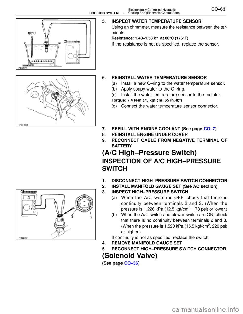
5. INSPECT WATER TEMPERATURE SENSORUsing an ohmmeter, measure the resistance between the ter-
minals.
Resistance: 1.48±1.58 k � at 80 5C (176 5F)
If the resistance is not as specified, replace the sensor.
6. REINSTALL WATER TEMPERATURE SENSOR (a) Install a new O±ring to the water temperature sensor.
(b) Apply soapy water to the O±ring.
(c) Install the water temperature sensor to the radiator.
Torque: 7.4 N Vm (75 kgf Vcm, 65 in. Vlbf)
(d) Connect the water temperature sensor connector.
7. REFILL WITH ENGINE COOLANT (See page CO±7)
8. REINSTALL ENGINE UNDER COVER
9. RECONNECT CABLE FROM NEGATIVE TERMINAL OF BATTERY
(A/C High±Pressure Switch)
INSPECTION OF A/C HIGH±PRESSURE
SWITCH
1. DISCONNECT HIGH±PRESSURE SWITCH CONNECTOR
2. INSTALL MANIFOLD GAUGE SET (See AC section)
3. INSPECT HIGH±PRESSURE SWITCH(a) Wh e n th e A/C switch is OFF, ch e ck th a t th e re iscontinuity between terminals 2 and 3. (When the
pressure is 1,226 kPa (12.5 kgf/cm
2, 178 psi) or lower.)
(b) When the A/C switch and blower switch are ON, check
that there is no continuity between terminals 2 and 3.
(When the pressure is 1,520 kPa (15.5 kgf/cm
2, 220 psi)
or higher.)
If continuity is not as specified, replace the switch.
4. REMOVE MANIFOLD GAUGE SET
5. RECONNECT HIGH±PRESSURE SWITCH CONNECTOR
(Solenoid Valve)
(See page CO±36)
±
COOLIING SYSTEM Electronically Controlled Hydraulic
Cooling Fan (Electronic Control Parts)CO±63
WhereEverybodyKnowsYourName
Page 1342 of 4087

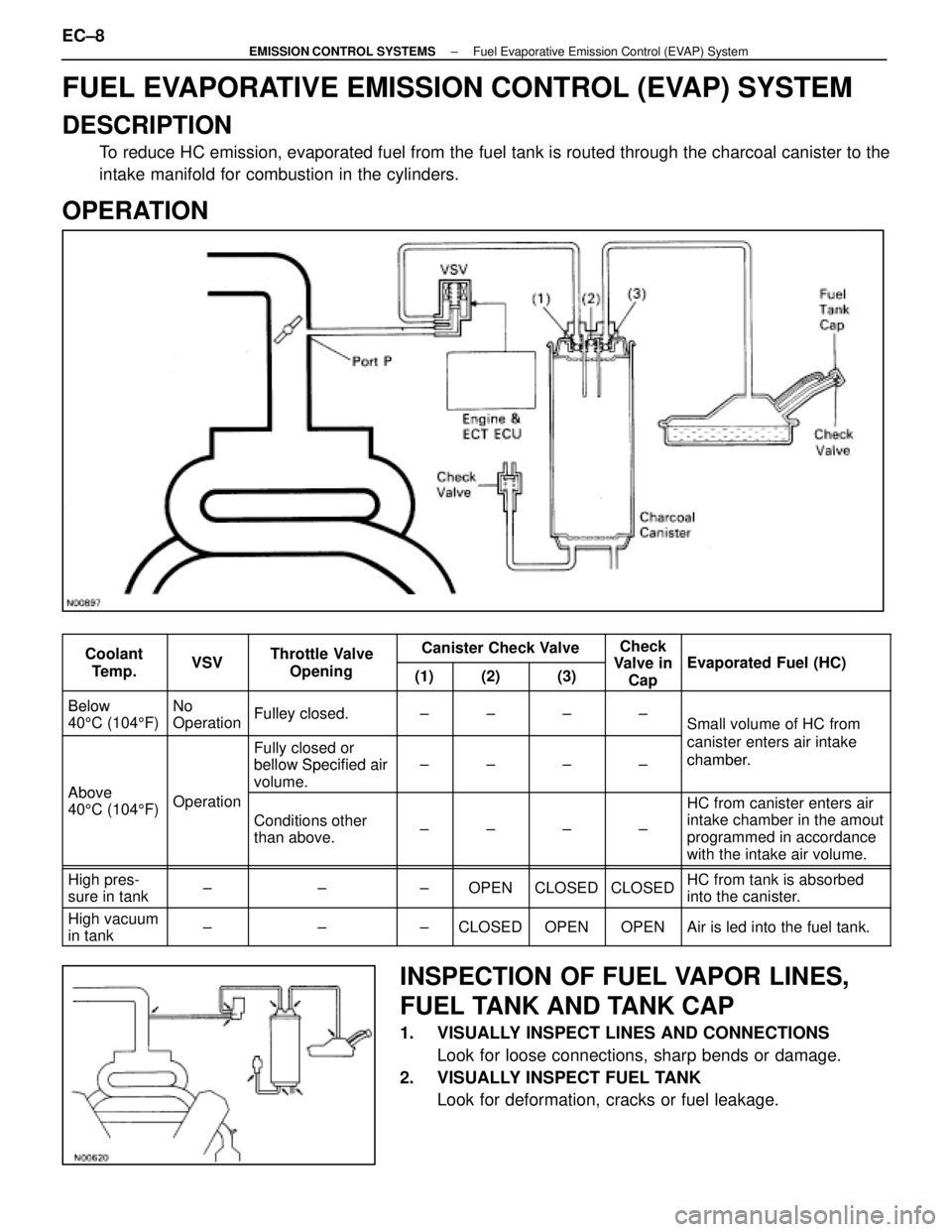
FUEL EVAPORATIVE EMISSION CONTROL (EVAP) SYSTEM
DESCRIPTION
To reduce HC emission, evaporated fuel from the fuel tank is routed throug\
h the charcoal canister to the
intake manifold for combustion in the cylinders.
OPERATION
CoolantVSVThrottle ValveCanister Check ValveCheck
Valve inEvaporated F el (HC)Coolant
Te m p .VSVThrottle Valve
Opening(1)(2)(3)Valve inCapEvaporated Fuel (HC)
BelowNoFulley closedBelow
40 5C (104 5F)
No
OperationFulley closed.±±±±Small volume of HC from
Fully closed or
bellow Specified air
canister enters air intake
chamber.
Above
bellow Specified air
volume.±±±±chamber.
Above
40 5C (104 5F)Operation
Conditions other
than above.±±±±
HC from canister enters air
intake chamber in the amout
programmed in accordance
with the intake air volume.
High pres-
sure in tank±±±OPENCLOSEDCLOSEDHC from tank is absorbed
into the canister.
High vacuum
in tank±±±CLOSEDOPENOPENAir is led into the fuel tank.
INSPECTION OF FUEL VAPOR LINES,
FUEL TANK AND TANK CAP
1. VISUALLY INSPECT LINES AND CONNECTIONS
Look for loose connections, sharp bends or damage.
2. VISUALLY INSPECT FUEL TANK Look for deformation, cracks or fuel leakage.
EC±8
±
EMISSION CONTROL SYSTEMS Fuel Evaporative Emission Control (EVAP) System
WhereEverybodyKnowsYourName