1991 LEXUS SC400 oil dipstick
[x] Cancel search: oil dipstickPage 1858 of 4087

ASSEMBLY OF ENGINE AND
TRANSMISSION
(See Components on page EM±73)1. (M/T) INSTALL CLUTCH DISC AND COVER
Torque: 19 N Vm (195 kgf Vcm, 14 ft Vlbf)
2. ASSEMBLE ENGINE AND TRANSMISSION
(See page AT±31)
Torque:
14 mm head bolt 37 N Vm (380 kgf Vcm, 27 ft Vlbf)
17 mm head bolt 72 N Vm (730 kgf Vcm, 53 ft Vlbf)
3. INSTALL STARTER
Torque: 39 N Vm (400 kgf Vcm, 29 ft Vlbf)
4. CONNECT ENGINE WIRE TO TRANSMISSION
5. (A/T)
INSTALL OIL COOLER PIPE
Torque: 34 N Vm (350 kgf Vcm, 25 ft Vlbf)
6. (A/T)
INSTALL OIL DIPSTICK GUIDE FOR TRANSMISSION
±
ENGINE MECHANICAL Cylinder BlockEM±103
WhereEverybodyKnowsYourName
Page 1865 of 4087
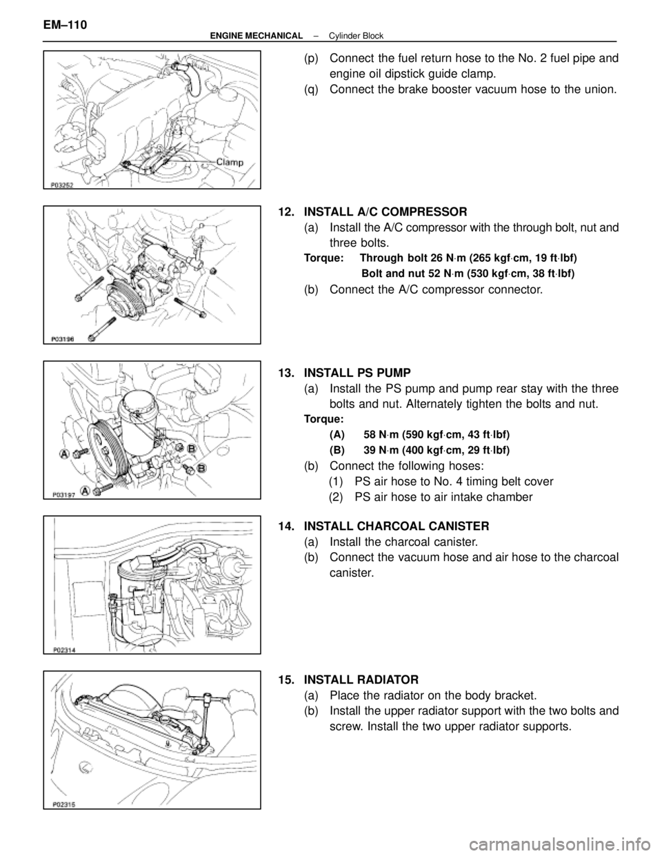
(p) Connect the fuel return hose to the No. 2 fuel pipe andengine oil dipstick guide clamp.
(q) Connect the brake booster vacuum hose to the union.
12. INSTALL A/C COMPRESSOR (a) Install the A/C compressor with the through bolt, nut and
three bolts.
Torque: Through bolt 26 N Vm (265 kgf Vcm, 19 ft Vlbf)
Bolt and nut 52 N Vm (530 kgf Vcm, 38 ft Vlbf)
(b) Connect the A/C compressor connector.
13. INSTALL PS PUMP (a) Install the PS pump and pump rear stay with the threebolts and nut. Alternately tighten the bolts and nut.
Torque:
(A) 58 N Vm (590 kgf Vcm, 43 ft Vlbf)
(B) 39 N Vm (400 kgf Vcm, 29 ft Vlbf)
(b) Connect the following hoses:
(1) PS air hose to No. 4 timing belt cover
(2) PS air hose to air intake chamber
14. INSTALL CHARCOAL CANISTER (a) Install the charcoal canister.
(b) Connect the vacuum hose and air hose to the charcoalcanister.
15. INSTALL RADIATOR (a) Place the radiator on the body bracket.
(b) Install the upper radiator support with the two bolts andscrew. Install the two upper radiator supports.
EM±110
±
ENGINE MECHANICAL Cylinder Block
WhereEverybodyKnowsYourName
Page 1890 of 4087
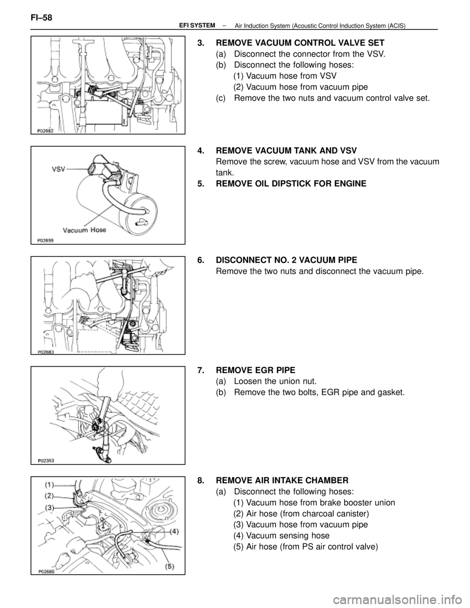
3. REMOVE VACUUM CONTROL VALVE SET(a) Disconnect the connector from the VSV.
(b) Disconnect the following hoses:(1) Vacuum hose from VSV
(2) Vacuum hose from vacuum pipe
(c) Remove the two nuts and vacuum control valve set.
4. REMOVE VACUUM TANK AND VSV Remove the screw, vacuum hose and VSV from the vacuum
tank.
5. REMOVE OIL DIPSTICK FOR ENGINE
6. DISCONNECT NO. 2 VACUUM PIPE Remove the two nuts and disconnect the vacuum pipe.
7. REMOVE EGR PIPE (a) Loosen the union nut.
(b) Remove the two bolts, EGR pipe and gasket.
8. REMOVE AIR INTAKE CHAMBER (a) Disconnect the following hoses:(1) Vacuum hose from brake booster union
(2) Air hose (from charcoal canister)
(3) Vacuum hose from vacuum pipe
(4) Vacuum sensing hose
(5) Air hose (from PS air control valve)
FI±58
±
EFI SYSTEM
Air Induction System (Acoustic Control Induction System (ACIS)
WhereEverybodyKnowsYourName
Page 1894 of 4087
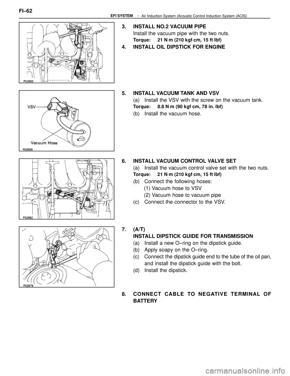
3. INSTALL NO.2 VACUUM PIPEInstall the vacuum pipe with the two nuts.
Torque: 21 N Vm (210 kgf Vcm, 15 ft Vlbf)
4. INSTALL OIL DIPSTICK FOR ENGINE
5. INSTALL VACUUM TANK AND VSV
(a) Install the VSV with the screw on the vacuum tank.
Torque: 8.8 N Vm (90 kgf Vcm, 78 in. Vlbf)
(b) Install the vacuum hose.
6. INSTALL VACUUM CONTROL VALVE SET (a) Install the vacuum control valve set with the two nuts.
Torque: 21 N Vm (210 kgf Vcm, 15 ft Vlbf)
(b) Connect the following hoses:
(1) Vacuum hose to VSV
(2) Vacuum hose to vacuum pipe
(c) Connect the connector to the VSV.
7. (A/T) INSTALL DIPSTICK GUIDE FOR TRANSMISSION
(a) Install a new O±ring on the dipstick guide.
(b) Apply soapy on the O±ring.
(c) Connect the dipstick guide end to the tube of the oil pan,
and install the dipstick guide with the bolt.
(d) Install the dipstick.
8. CONNECT CABLE TO NEGATIVE TERMINAL OF BATTERY
FI±62
±
EFI SYSTEM
Air Induction System (Acoustic Control Induction System (ACIS)
WhereEverybodyKnowsYourName
Page 2019 of 4087
IF VEHICLE IS EQUIPPED WITH MOBILE
RADIO SYSTEM (HAM, CB, ETC.)
The ECU has been designed so that it will not be affected by out-
side interference. However, if your vehicle is equipped with a CB
radio transceiver, etc. (even one with about 10 W output), it may,
at times, have an effect upon ECU operation, especially if the an-
tenna and feeder are installed nearby.
Therefore, observe the following precautions:
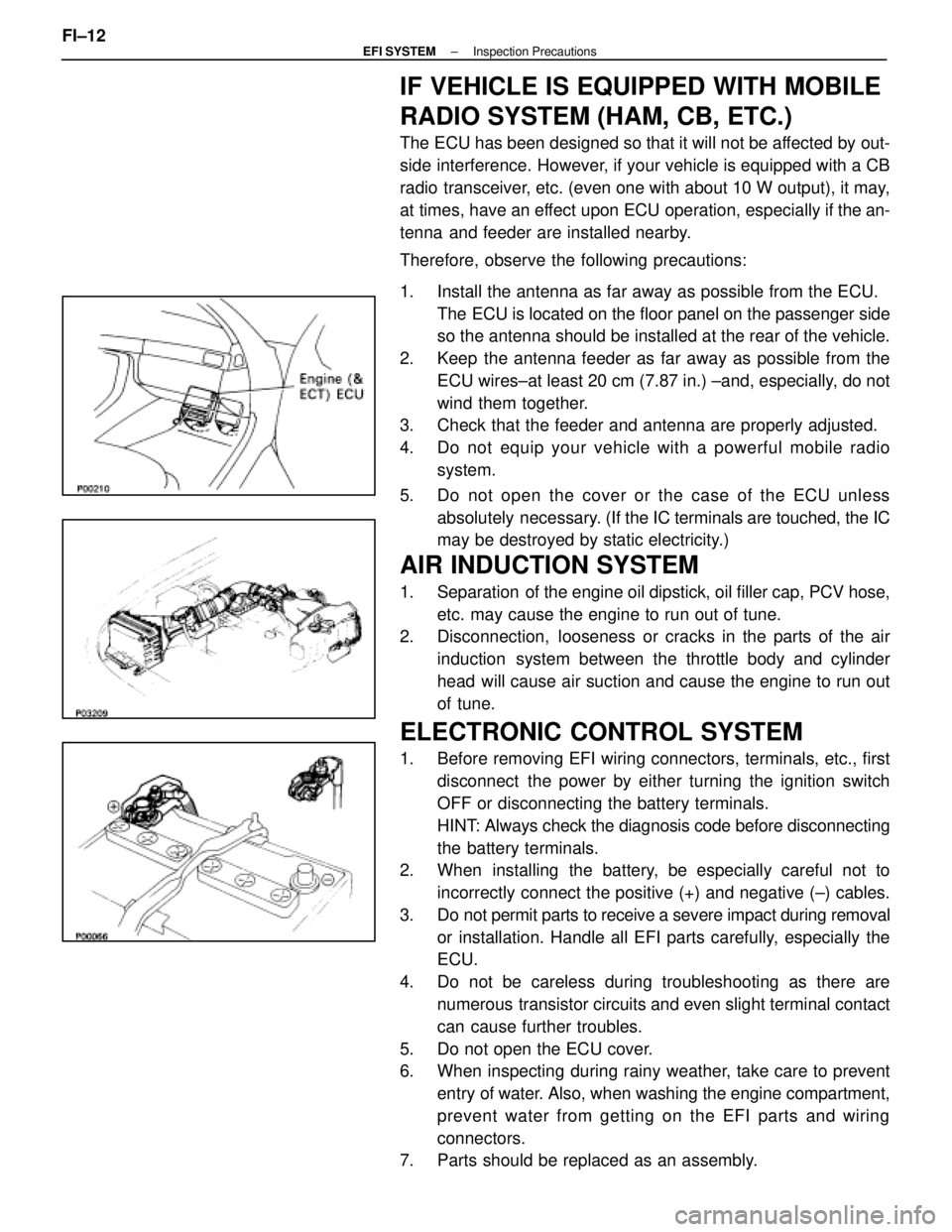
1. Install the antenna as far away as possible from the ECU. The ECU is located on the floor panel on the passenger side
so the antenna should be installed at the rear of the vehicle.
2. Keep the antenna feeder as far away as possible from the ECU wires±at least 20 cm (7.87 in.) ±and, especially, do not
wind them together.
3. Check that the feeder and antenna are properly adjusted.
4. Do not equip your vehicle with a powerful mobile radio
system.
5. Do not open the cover or the case of the ECU unless absolutely necessary. (If the IC terminals are touched, the IC
may be destroyed by static electricity.)
AIR INDUCTION SYSTEM
1. Separation of the engine oil dipstick, oil filler cap, PCV hose,
etc. may cause the engine to run out of tune.
2. Disconnection, looseness or cracks in the parts of the air
induction system between the throttle body and cylinder
head will cause air suction and cause the engine to run out
of tune.
ELECTRONIC CONTROL SYSTEM
1. Before removing EFI wiring connectors, terminals, etc., firstdisconnect the power by either turning the ignition switch
OFF or disconnecting the battery terminals.
HINT: Always check the diagnosis code before disconnecting
the battery terminals.
2. When installing the battery, be especially careful not to
incorrectly connect the positive (+) and negative (±) cables.
3. Do not permit parts to receive a severe impact during removal or installation. Handle all EFI parts carefully, especially the
ECU.
4. Do not be careless during troubleshooting as there are numerous transistor circuits and even slight terminal contact
can cause further troubles.
5. Do not open the ECU cover.
6. When inspecting during rainy weather, take care to prevent entry of water. Also, when washing the engine compartment,
prevent water from getting on the EFI parts and wiring
connectors.
7. Parts should be replaced as an assembly.
FI±12
±
EFI SYSTEM Inspection Precautions
WhereEverybodyKnowsYourName
Page 2024 of 4087
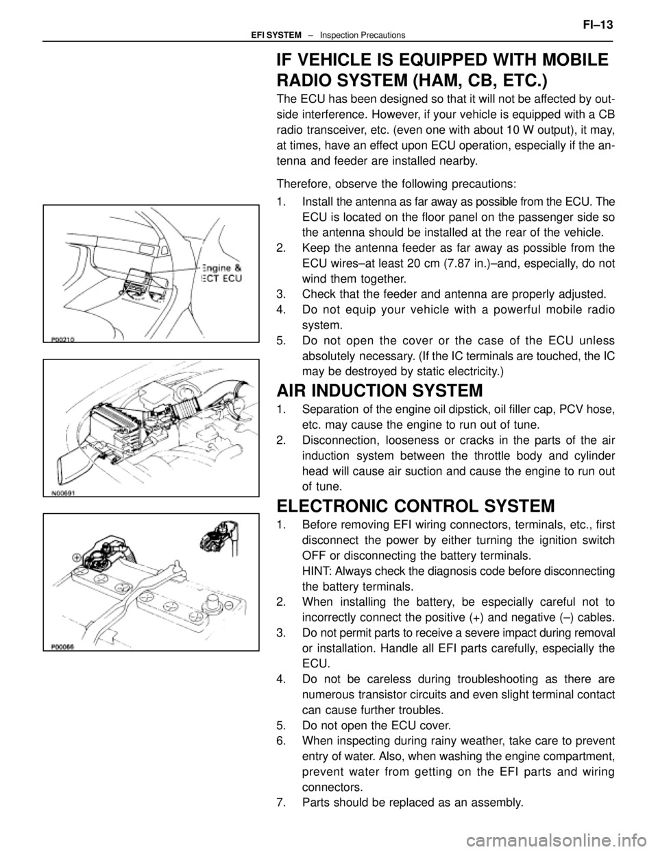
IF VEHICLE IS EQUIPPED WITH MOBILE
RADIO SYSTEM (HAM, CB, ETC.)
The ECU has been designed so that it will not be affected by out-
side interference. However, if your vehicle is equipped with a CB
radio transceiver, etc. (even one with about 10 W output), it may,
at times, have an effect upon ECU operation, especially if the an-
tenna and feeder are installed nearby.
Therefore, observe the following precautions:
1. Install the antenna as far away as possible from the ECU. The
ECU is located on the floor panel on the passenger side so
the antenna should be installed at the rear of the vehicle.
2. Keep the antenna feeder as far away as possible from the ECU wires±at least 20 cm (7.87 in.)±and, especially, do not
wind them together.
3. Check that the feeder and antenna are properly adjusted.
4. Do not equip your vehicle with a powerful mobile radio
system.
5. Do not open the cover or the case of the ECU unless absolutely necessary. (If the IC terminals are touched, the IC
may be destroyed by static electricity.)
AIR INDUCTION SYSTEM
1. Separation of the engine oil dipstick, oil filler cap, PCV hose,
etc. may cause the engine to run out of tune.
2. Disconnection, looseness or cracks in the parts of the air induction system between the throttle body and cylinder
head will cause air suction and cause the engine to run out
of tune.
ELECTRONIC CONTROL SYSTEM
1. Before removing EFI wiring connectors, terminals, etc., firstdisconnect the power by either turning the ignition switch
OFF or disconnecting the battery terminals.
HINT: Always check the diagnosis code before disconnecting
the battery terminals.
2. When installing the battery, be especially careful not to
incorrectly connect the positive (+) and negative (±) cables.
3. Do not permit parts to receive a severe impact during removal or installation. Handle all EFI parts carefully, especially the
ECU.
4. Do not be careless during troubleshooting as there are numerous transistor circuits and even slight terminal contact
can cause further troubles.
5. Do not open the ECU cover.
6. When inspecting during rainy weather, take care to prevent entry of water. Also, when washing the engine compartment,
prevent water from getting on the EFI parts and wiring
connectors.
7. Parts should be replaced as an assembly. FI±13
EFI SYSTEM
± Inspection Precautions
WhereEverybodyKnowsYourName
Page 2073 of 4087
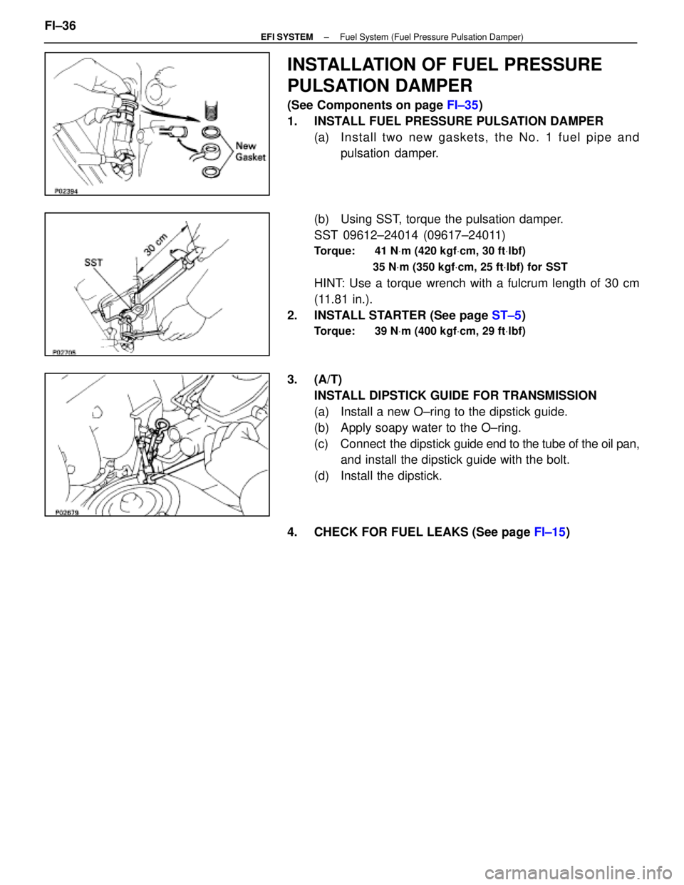
INSTALLATION OF FUEL PRESSURE
PULSATION DAMPER
(See Components on page FI±35)
1. INSTALL FUEL PRESSURE PULSATION DAMPER (a) In sta ll two ne w ga ske ts, th e No . 1 fu e l pip e an dpulsation damper.
(b) Using SST, torque the pulsation damper.
SST 09612±24014 (09617±24011)
Torque: 41 N Vm (420 kgf Vcm, 30 ft Vlbf)
35 N Vm (350 kgf Vcm, 25 ft Vlbf) for SST
HINT: Use a torque wrench with a fulcrum length of 30 cm
(11.81 in.).
2. INSTALL STARTER (See page ST±5)
Torque: 39 N Vm (400 kgf Vcm, 29 ft Vlbf)
3. (A/T)
INSTALL DIPSTICK GUIDE FOR TRANSMISSION
(a) Install a new O±ring to the dipstick guide.
(b) Apply soapy water to the O±ring.
(c) Connect the dipstick guide end to the tube of the oil pan,
and install the dipstick guide with the bolt.
(d) Install the dipstick.
4. CHECK FOR FUEL LEAKS (See page FI±15)
FI±36
±
EFI SYSTEM Fuel System (Fuel Pressure Pulsation Damper)
WhereEverybodyKnowsYourName
Page 2123 of 4087

A pressure feeding lubrication system has been adopted to supply oil to \
the moving parts of this engine. The
lubrication system consists of an oil pan, oil pump, oil filter and other external p\
arts which supply oil to the moving
parts in the engine block. The oil circuit is shown in the illustration at th\
e top of the previous page. Oil from the
oil pan is pumped up by the oil pump. After it passes through the oil fi\
lter, it is fed through the various oil holes
in the crankshaft and cylinder block. After passing through the cylinder b\
lock and performing its lubricating func-
tion, the oil is returned by gravity to the oil pan. A dipstick on the center\
left side of the cylinder block is provided
to check the oil level.
OIL PUMP The oil pump pumps up oil from the oil pan and sends it under pressure to t\
he various parts of the engine.
An oil strainer is mounted in front of the inlet to the oil pump. The oil \
pump itself is a trochoid type pump, inside
of which there is a drive rotor and a driven rotor. When the drive rotor rotates, the driven rotor rotates in the same
direction, and since the axis of the driven rotor shaft is different from the center of the driven rotor, the space
between the two rotors is changed as they rotate. Oil is drawn in when the space\
is wide and is discharged when
the space in narrow.
OIL PRESSURE REGULATOR At high engine speeds, the engine oil supplied by the oil pump exceeds the\
capacity of the engine to utilize
it. For that reason, the oil pressure regulator works to prevent an over\
supply of oil. During normal oil supply, a
coil spring and valve keep the bypass closed, but when too much oil is being \
fed, the pressure become extremely
high, overpowering the force of the spring and opening the valves. This allow\
s the excess oil to flow through
the valve and return to the oil pump inlet.
OIL FILTER The oil filter is a full flow type filter with a built±in paper filter e\
lement. Particles of metal from wear, airborne
dirt, carbon and other impurities can get into the oil during use and co\
uld cause accelerated wear or seizing if
allowed to circulate through the engine. The oil filter, integrated into the oil line, removes these impurities as the
oil passes through it. The filter is mounted outside the engine to simplify\
replacement of the filter element. A relief
valve is also included ahead of the filter element to relieve the high oil pr\
essure in case the filter element be-
comes clogged with impurities. The relief valve opens when the oil pressure o\
verpowers the force of the spring.
Oil passing through the relief valve by±passes the oil filter and flo\
ws directly into the main oil hole in the engine.
±
LUBRICATION SYSTEM PrecautionsLU±3
WhereEverybodyKnowsYourName