Page 1654 of 4087
ENGINE TUNE±UP
INSPECTION OF ENGINE COOLANT
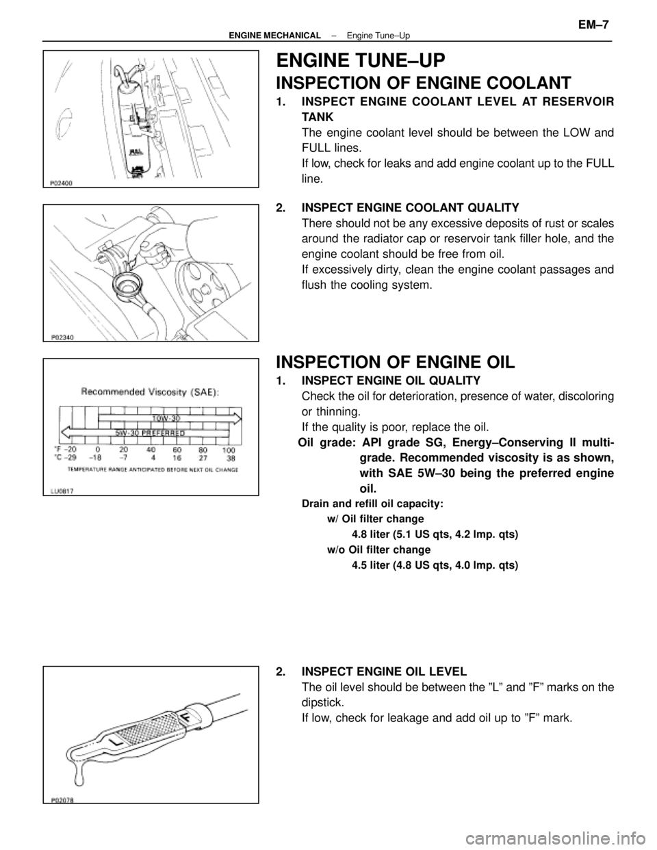
1. INSPECT ENGINE COOLANT LEVEL AT RESERVOIRTANK
The engine coolant level should be between the LOW and
FULL lines.
If low, check for leaks and add engine coolant up to the FULL
line.
2. INSPECT ENGINE COOLANT QUALITY There should not be any excessive deposits of rust or scales
around the radiator cap or reservoir tank filler hole, and the
engine coolant should be free from oil.
If excessively dirty, clean the engine coolant passages and
flush the cooling system.
INSPECTION OF ENGINE OIL
1. INSPECT ENGINE OIL QUALITYCheck the oil for deterioration, presence of water, discoloring
or thinning.
If the quality is poor, replace the oil.
Oil grade: API grade SG, Energy±Conserving II multi- grade. Recommended viscosity is as shown,
with SAE 5W±30 being the preferred engine
oil.
Drain and refill oil capacity:
w/ Oil filter change
4.8 liter (5.1 US qts, 4.2 lmp. qts)
w/o Oil filter change 4.5 liter (4.8 US qts, 4.0 lmp. qts)
2. INSPECT ENGINE OIL LEVELThe oil level should be between the ºLº and ºFº marks on the
dipstick.
If low, check for leakage and add oil up to ºFº mark.
±
ENGINE MECHANICAL Engine Tune±UpEM±7
WhereEverybodyKnowsYourName
Page 1667 of 4087
ENGINE TUNE±UP
INSPECTION OF ENGINE COOLANT
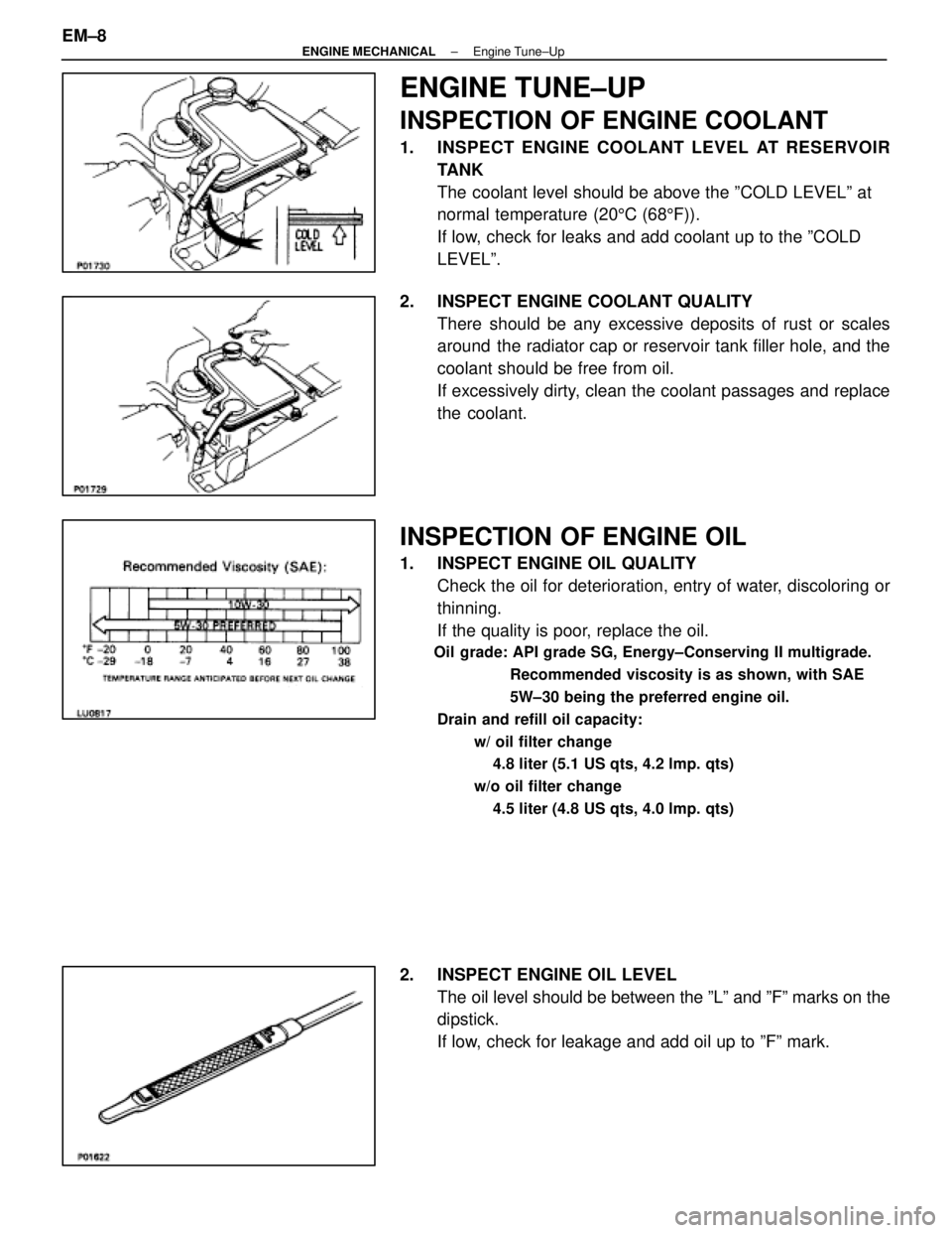
1. INSPECT ENGINE COOLANT LEVEL AT RESERVOIRTANK
The coolant level should be above the ºCOLD LEVELº at
normal temperature (20 5C (68 5F)).
If low, check for leaks and add coolant up to the ºCOLD
LEVELº.
2. INSPECT ENGINE COOLANT QUALITY There should be any excessive deposits of rust or scales
around the radiator cap or reservoir tank filler hole, and the
coolant should be free from oil.
If excessively dirty, clean the coolant passages and replace
the coolant.
INSPECTION OF ENGINE OIL
1. INSPECT ENGINE OIL QUALITYCheck the oil for deterioration, entry of water, discoloring or
thinning.
If the quality is poor, replace the oil.
Oil grade: API grade SG, Energy±Conserving II multigrade.
Recommended viscosity is as shown, with SAE
5W±30 being the preferred engine oil.
Drain and refill oil capacity: w/ oil filter change4.8 liter (5.1 US qts, 4.2 lmp. qts)
w/o oil filter change 4.5 liter (4.8 US qts, 4.0 lmp. qts)
2. INSPECT ENGINE OIL LEVEL The oil level should be between the ºLº and ºFº marks on the
dipstick.
If low, check for leakage and add oil up to ºFº mark.
EM±8
±
ENGINE MECHANICAL Engine Tune±Up
WhereEverybodyKnowsYourName
Page 1734 of 4087
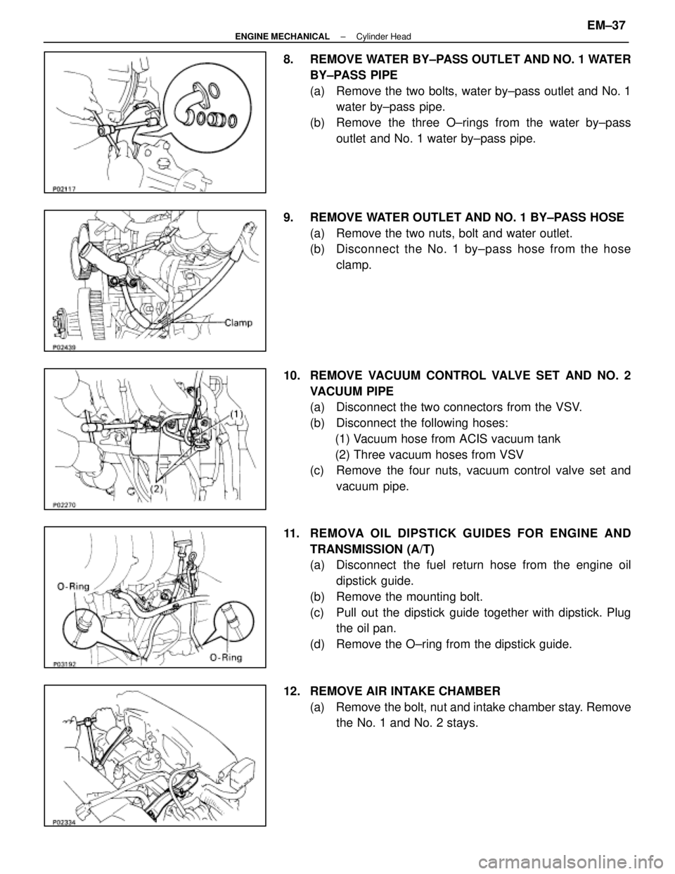
8. REMOVE WATER BY±PASS OUTLET AND NO. 1 WATERBY±PASS PIPE
(a) Remove the two bolts, water by±pass outlet and No. 1water by±pass pipe.
(b) Remove the three O±rings from the water by±pass outlet and No. 1 water by±pass pipe.
9. REMOVE WATER OUTLET AND NO. 1 BY±PASS HOSE (a) Remove the two nuts, bolt and water outlet.
(b) Disc onnect the No. 1 by±pass hose from the hose
clamp.
10. REMOVE VACUUM CONTROL VALVE SET AND NO. 2 VACUUM PIPE
(a) Disconnect the two connectors from the VSV.
(b) Disconnect the following hoses:(1) Vacuum hose from ACIS vacuum tank
(2) Three vacuum hoses from VSV
(c) Remove the four nuts, vacuum control valve set and
vacuum pipe.
11. REMOVA OIL DIPSTICK GUIDES FOR ENGINE AND TRANSMISSION (A/T)
(a) Disconnect the fuel return hose from the engine oildipstick guide.
(b) Remove the mounting bolt.
(c) Pull out the dipstick guide together with dipstick. Plug the oil pan.
(d) Remove the O±ring from the dipstick guide.
12. REMOVE AIR INTAKE CHAMBER (a) Remove the bolt, nut and intake chamber stay. Removethe No. 1 and No. 2 stays.
±
ENGINE MECHANICAL Cylinder HeadEM±37
WhereEverybodyKnowsYourName
Page 1757 of 4087
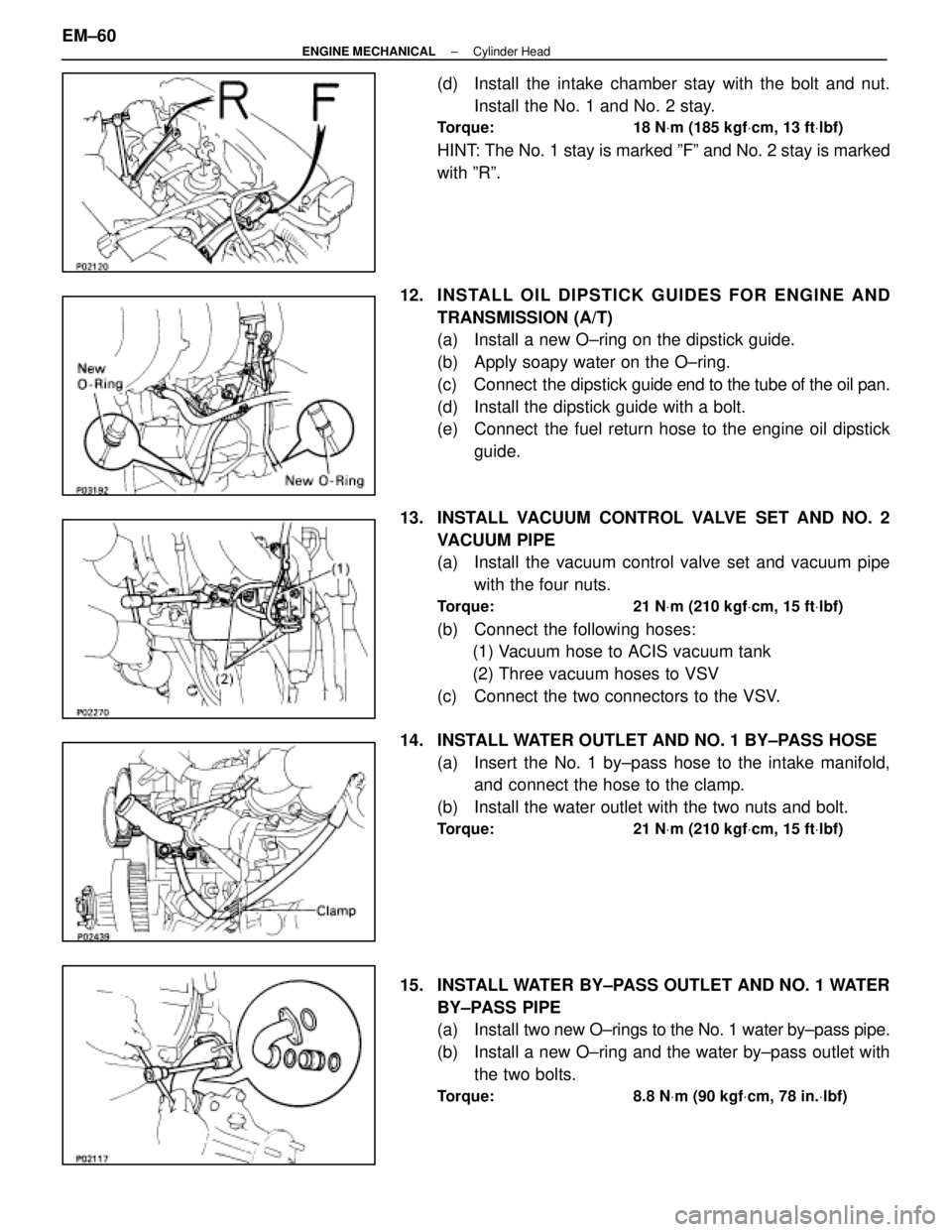
(d) Install the intake chamber stay with the bolt and nut.Install the No. 1 and No. 2 stay.
Torque: 18 N Vm (185 kgf Vcm, 13 ft Vlbf)
HINT: The No. 1 stay is marked ºFº and No. 2 stay is marked
with ºRº.
12. INS TALL OIL DIP S TICK GUIDE S FO R ENG INE AND TRANSMISSION (A/T)
(a) Install a new O±ring on the dipstick guide.
(b) Apply soapy water on the O±ring.
(c) Connect the dipstick guide end to the tube of the oil pan.
(d) Install the dipstick guide with a bolt.
(e) Connect the fuel return hose to the engine oil dipstick guide.
13. INSTALL VACUUM CONTROL VALVE SET AND NO. 2 VACUUM PIPE
(a) Install the vacuum control valve set and vacuum pipewith the four nuts.
Torque: 21 N Vm (210 kgf Vcm, 15 ft Vlbf)
(b) Connect the following hoses:
(1) Vacuum hose to ACIS vacuum tank
(2) Three vacuum hoses to VSV
(c) Connect the two connectors to the VSV.
14. INSTALL WATER OUTLET AND NO. 1 BY±PASS HOSE (a) Insert the No. 1 by±pass hose to the intake manifold,and connect the hose to the clamp.
(b) Install the water outlet with the two nuts and bolt.
Torque: 21 N Vm (210 kgf Vcm, 15 ft Vlbf)
15. INSTALL WATER BY±PASS OUTLET AND NO. 1 WATER
BY±PASS PIPE
(a) Install two new O±rings to the No. 1 water by±pass pipe.
(b) Install a new O±ring and the water by±pass outlet with the two bolts.
Torque: 8.8 N Vm (90 kgf Vcm, 78 in. Vlbf)
EM±60±
ENGINE MECHANICAL Cylinder Head
WhereEverybodyKnowsYourName
Page 1770 of 4087
(c) Remove the four nuts, water by±pass joint and twogaskets.
31. REMOVE REAR WATER BY±PASS JOINT (a) Remove the bolt holding the water by±pass pipe to theengine hanger.
(b) Remove the four nuts, water by±pass joint and two gaskets.
32. REMOVE OIL DIPSTICK AND GUIDE FOR ENGINE (a) Remove the mounting bolt.
(b) Pull out the dipstick guide together with the dipstick.
(c) Remove the O±ring from the dipstick guide.
33. REMOVE OIL DIPSTICK AND GUIDE FOR A/T
34. REMOVE EGR PIPE (a) Remove the two nuts holding the EGR pipe to the RHexhaust pipe.
(b) Remove the EGR pipe and gasket.
35. DISCONNECT GROUND STRAP FROM RH CYLINDER HEAD
36. DISCONNECT ENGINE WIRE FROM RH CYLINDER HEAD
Remove the two bolts, and disconnect the engine wire.
±
ENGINE MECHANICAL Cylinder HeadsEM±69
WhereEverybodyKnowsYourName
Page 1804 of 4087
12. INSTALL ENGINE HANGERSInstall the engine hanger with the two bolts.
Install the two engine hangers.
Torque: 37 N Vm (380 kgf Vcm, 27 ft Vlbf)
13. CONNECT GROUND STRAP TO RH CYLINDER HEAD
14. INSTALL ENGINE WIRE TO RH CYLINDER HEAD
Install the engine wire with the two bolts.
15. INSTALL ENGINE WIRE TO LH CYLINDER HEAD Install the engine wire with the five bolts.
16. INSTALL EGR PIPE TO RH EXHAUST MANIFOLD Install a new gasket and the EGR pipe with the two new nuts.
Torque: 18 N Vm (185 kgf Vcm, 13 ft Vlbf)
17. INSTALL OIL DIPSTICK AND GUIDE FOR ENGINE
(a) Install a new O±ring to the dipstick guide.
(b) Apply a light of engine oil on the O±ring.
(c) Push in the dipstick guide into the guide hole of the No.1
oil pan.
(d) Install the dipstick guide with the bolt.
(e) Install the oil dipstick.
18. INSTALL OIL DIPSTICK AND GUIDE FOR A/T
±
ENGINE MECHANICAL Cylinder HeadsEM±103
WhereEverybodyKnowsYourName
Page 1821 of 4087
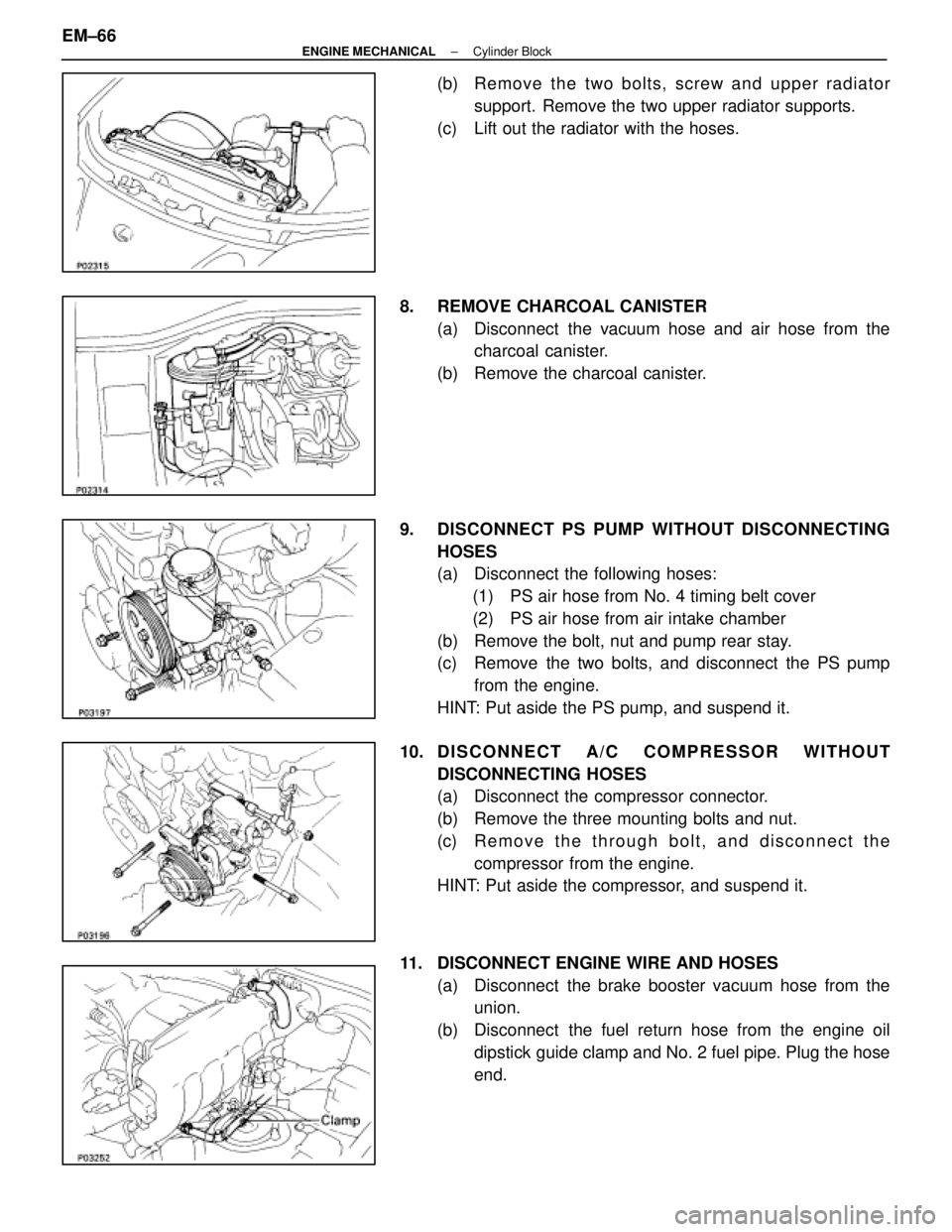
(b) Remove the two bolts, screw and upper radiatorsupport. Remove the two upper radiator supports.
(c) Lift out the radiator with the hoses.
8. REMOVE CHARCOAL CANISTER (a) Disconnect the vacuum hose and air hose from thecharcoal canister.
(b) Remove the charcoal canister.
9. DISCONNECT PS PUMP WITHOUT DISCONNECTING HOSES
(a) Disconnect the following hoses:(1) PS air hose from No. 4 timing belt cover
(2) PS air hose from air intake chamber
(b) Remove the bolt, nut and pump rear stay.
(c) Remove the two bolts, and disconnect the PS pump from the engine.
HINT: Put aside the PS pump, and suspend it.
10. D I S C O N N E C T A / C C O M P R ESSOR WITHOUT
DISCONNECTING HOSES
(a) Disconnect the compressor connector.
(b) Remove the three mounting bolts and nut.
(c) R e m o v e t h e t h r ough bolt, and disconnect the
compressor from the engine.
HINT: Put aside the compressor, and suspend it.
11. DISCONNECT ENGINE WIRE AND HOSES (a) Disconnect the brake booster vacuum hose from theunion.
(b) Disconnect the fuel return hose from the engine oil dipstick guide clamp and No. 2 fuel pipe. Plug the hose
end.
EM±66
±
ENGINE MECHANICAL Cylinder Block
WhereEverybodyKnowsYourName
Page 1828 of 4087
COMPONENTS FOR SEPARATION AND
ASSEMBLY OF ENGINE AND
TRANSMISSION
SEPARATION OF ENGINE AND
TRANSMISSION
1. (A/T)REMOVE OIL DIPSTICK GUIDE FOR TRANSMISSION
2. (A/T) REMOVE OIL COOLER PIPES FOR TRANSMISSION
3. DISCONNECT ENGINE WIRE FROM TRANSMISSION
4. REMOVE STARTER
5. SEPARATE ENGINE AND TRANSMISSION
6. (M/T) REMOVE CLUTCH COVER AND DISC
±
ENGINE MECHANICAL Cylinder BlockEM±73
WhereEverybodyKnowsYourName