Page 3211 of 4087
YESNo
HINT: If diagnostic trouble code 22 is output, perform the following troubles\
hooting:
1Is diagnostic trouble code 22 output again?
C
PClear malfunction.
1. Turn ignition switch LOCK, and wait at least 20 sec-onds.
2. Turn ignition switch ACC or ON, and wait at least 20 seconds.
3. Using SST, connect terminals Tc and E
1 of DLC2.
SST 09843±18020
4. Check diagnostic trouble code.
Using simulation method, reproduce malfunction symp-
toms (See page RS±65).
Replace center airbag sensor assembly.
±
SUPPLEMENTAL RESTRAINT SYSTEM TROUBLESHOOTINGRS±107
WhereEverybodyKnowsYourName
Page 3212 of 4087
DTC31Center Airbag Sensor Assembly Malfunction
CIRCUIT DESCRIPTION
The center airbag sensor assembly consists of center airbag sensor, safing sensors, ignition control and drive
circuit, diagnosis circuit, etc.
It receives signals from the airbag sensors, judges whether or not the SRS must be deploy, and diagnoses sys-
tem malfunction.
Diagnostic trouble code 31 is recorded when occurrence of a malfunction in the cen\
ter airbag assembly is de-
tected.
DTC No.Trouble Area
31�Center airbag sensor assembly malfunction.
DIAGNOSTIC CHARTDIAGNOSTIC CHART
HINT: When a malfunction code other than code 31 is displayed at the same time, first repair the malfunction
indicated by the malfunction code other than code 31.
(See page RS±65).
RS±108±
SUPPLEMENTAL RESTRAINT SYSTEM TROUBLESHOOTING
WhereEverybodyKnowsYourName
Page 3213 of 4087
YESNO
INSPECTION PROCEDURE
HINT: When a malfunction code other than code 31 is displayed at the same time, first repair the malfunction
indicated by the malfunction code other than 31.
1Is diagnostic rouble code 31 output again?
C
PClear malfunction.
1. Turn ignition switch LOCK, and wait at least 20 sec-onds.
2. Turn ignition switch ACC or ON, and wait at least 20 seconds.
3. Repeat operation in step (1) and (2) at least 5 times.
4. Using SST, connect terminals Tc and E
1 of DLC2.
SST 09843±18020
5. Check diagnostic trouble code.
Using simulation method, reproduce malfunction symp-
toms (See page RS±65).
Replace center airbag sensor assembly.
±
SUPPLEMENTAL RESTRAINT SYSTEM TROUBLESHOOTINGRS±109
WhereEverybodyKnowsYourName
Page 3860 of 4087
218COMBINATION METER
1E
81E 13
1E
12 1H 12
1J
1
3D
23A 3
3D
13D 11
1E
4
1G
9
1K
12
1E18 3D
13 3A
4
IG1
8BU1 4BU110 BU1 3
IG3
1 IK1
8
IK1
9IK2 24
IJ 1
5 1
IF BK
A
14 A 11 C 1
A
15 A 10 B 6A 8C8C 7C 9
C
21 C 22
132
L±R
FROM POWER SOURCE SYSTEM
(
SEE PAGE 56 )
4
Y
W±B W±B
B±O
W±R
YYY
Y±G Y±G Y±G Y±G B±Y
R
Y±B
B±W B±Y
B
Y±G
BR±B
BR
Y±G
B
B±Y
B±W Y±B
W±B B±Y
B±Y
W±B W±B
10A
GAUGE
15A
ECU±B
7. 5A
IGN
FUEL SENDER
IGNITER NO. 1 WATER TEMP.
SENDER
A
1A 2A 3
B
1 COMBINATION METER
TO CENTE R AIRB AG
SENSOR ASSEMBLY
TA CH
C12 , C1 3 , C 14
F1 7 ,
F18
I2 W3
ABC
B A SPEED SENSOR NO. 1
CHARGE
AIRBAG
HIGH BEAM
FUEL
FUEL
WATER. TEMP TACHO
S3
VCC OUT GND
2
B
7
R±W
15A
HEAD (
RH )
( FOR USA )
HEAD
( RH±LWR )
( FOR
CA NADA )
3B
2
B±Y
B±Y
TO CHECK CONNECTOR
( E/G )
3E
10
B±Y
TO CHECK CONNECTOR
( RM )
IK1
23
R
(
CANADA )
(USA )
TO DIMMER SW
[COMB. SW] R±W
IG1
9
IG1+ R
L±R
IK1
7
2 L
ALTERNAOR BR
IE1
12
R±W
IJ1
10
A1 0
WhereEverybodyKnowsYourName
Page 3868 of 4087

26
ELECTRICAL WIRING ROUTING
Position of Parts in Engine Compartment
A 1 A/C Ambient Temp. Sensor E 1 ECT Solenoid
A 2 A/C Lock Sensor and A/C Magnetic Clutch E 2 EFI Water Temp. Sensor
A 3 A/C High Pressure SW E 3 EGR Gas Temp. Sensor (for USA Spec.)
A 4 ABS Actuator E 5 Engine Hood Courtesy SW
A 5 ABS Actuator (w/ Traction Control) E 6 Engine Oil Level Warning SW
A 6 ABS Actuator (w/ Traction Control)
A 7 ABS Speed Sensor Front LH F 1 Front Airbag Sensor LH
A 8 ABS Speed Sensor Front RH F 2 Front Airbag Sensor RH
A 9 Air Flow Meter F 3 Front Clearance Light LH
A 10 Alternator F 4 Front Clearance Light RH
A 11 Alternator F 5Front Side Marker Light LH
A 33 ABS Actuator (w/o Traction Control) F 6 Front Side Marker Light RH F 7 Front Turn Signal Light LH
B 1 Brake Fluid Level SW F 8 Front Turn Signal Light RH
B 6 Back±Up Light SW (for M/T) F 9 Fuse Block
C 3 Check Connector H 1 Headlight Hi LH
C 6 Cornering Light LH H 2 Headlight Hi RH
C 7 Cornering Light RH H 3 Headlight Lo LH
C 8 Cruise Control Actuator H 4 Headlight Lo RH H 5 Horn LH
D 13 Distributor H 6 Horn RH
WhereEverybodyKnowsYourName
Page 3870 of 4087

28
ELECTRICAL WIRING ROUTING
Position of Parts in Instrument Panel
A 12 A/C Control Assembly C 9 CD Player
A 13 A/C Control Assembly C 10 Center Airbag Sensor Assembly
A 14 A/C Control Assembly C 11 Cigarette Lighter
A 15 A/C Control SW and Radio SW C 12 Combination Meter
A 16 A/C Evaporator Temp. Sensor C 13 Combination Meter
A 17 A/C Power Transistor C 14Combination Meter
A 18 A/C Power Transistor C 15 Combination SW
A 19 A/C Room Temp. Sensor C 16 Combination SW
A 20 A/C Solar Sensor C 17 Combination SW
A 21 A/T Indicator Light (for Shift Lever) C 19 Cruise Control ECU
A 22 ABS ECU (for M/T, w/o Traction Control) C 23 Clutch Start SW
A 23 ABS ECU (for M/T, w/o Traction Control) C 24 Cruise Control Clutch SW
A 24 ABS and Traction ECU
A 25 ABS and Traction ECU D 1 Diode (for Brake Fluid Level)
A 26 ABS and Traction ECU D 2 Diode (for Parking Brake)
A 27 Air Mix Control Servo Motor D 3 Diode (for Tension Reduser)
A 28 Air Vent Mode Control Servo Motor
A 29 Airbag Squib E 8 ECT Pattern Select SW
A 33 Air Inlet Control Servo Motor E 9 Engine and ECT ECU (for A/T) E 10 Engine and ECT ECU (for A/T)
B 2 Blower Motor E 11 Engine ECU (for M/T)
B 3 Blower Resistor (for Low Speed) E 12 Engine ECU (for M/T)
F 10 Fuel Lid Opener SW
G 1 Glove Box Light
G 2 Glove Box Light SW
WhereEverybodyKnowsYourName
Page 3916 of 4087

1
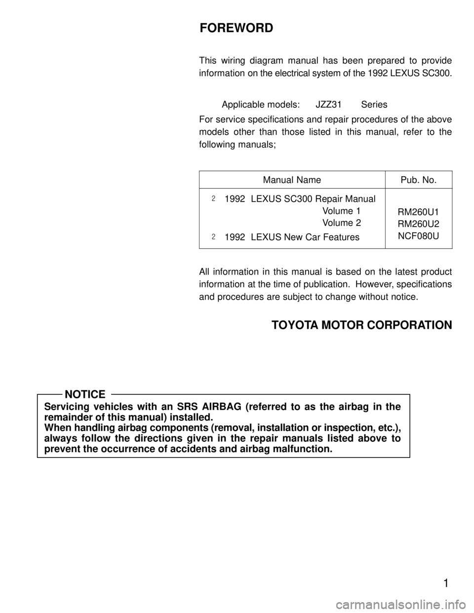
FOREWORD
This wiring diagram manual has been prepared to provide
information on the electrical system of the 1992 LEXUS SC300.
Applicable models: JZZ31 Series
For service specifications and repair procedures of the above
models other than those listed in this manual, refer to the
following manuals;
Manual Name
Pub. No.
���1992 LEXUS SC300 Repair Manual
Volume 1
Volume 2
��� 1992 LEXUS New Car Features
RM260U1
RM260U2
NCF080U
All information in this manual is based on the latest product
information at the time of publication. However, specifications
and procedures are subject to change without notice.
TOYOTA MOTOR CORPORATION
Servicing vehicles with an SRS AIRBAG (referred to as the airbag in the
remainder of this manual) installed.
When handling airbag components (removal, installation or inspection, etc.)\
,
always follow the directions given in the repair manuals listed above to
prevent the occurrence of accidents and airbag malfunction.
NOTICE
WhereEverybodyKnowsYourName
Page 3974 of 4087

1234
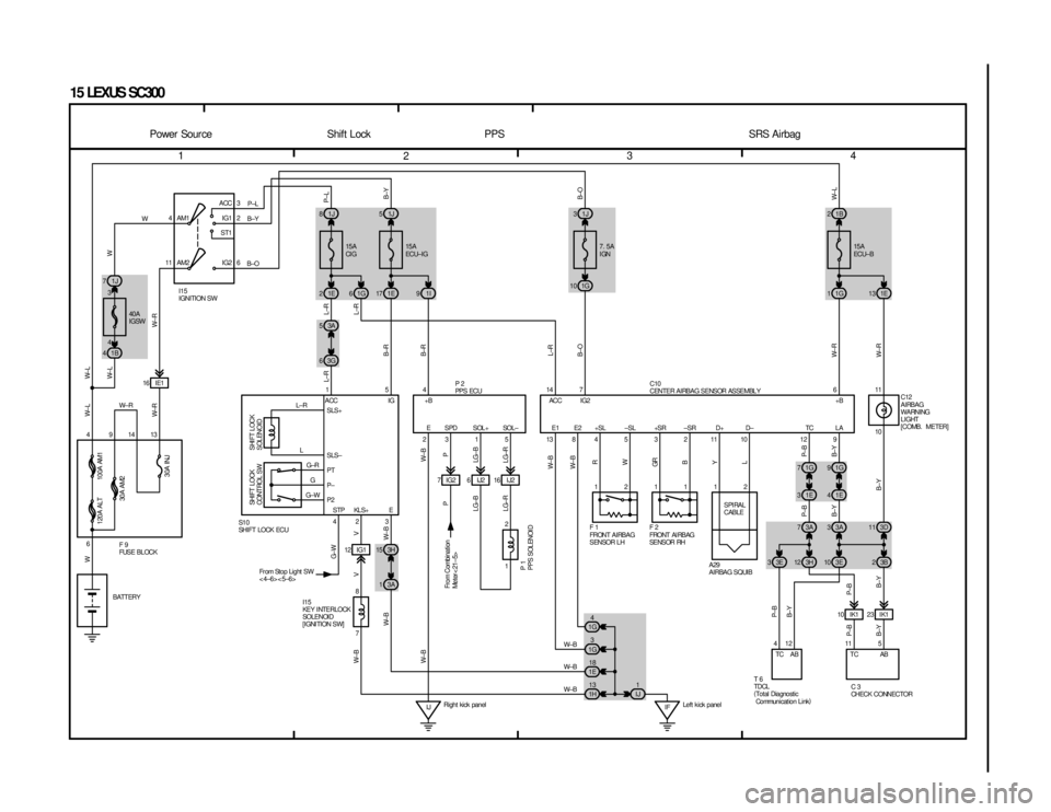
15 LEXUS SC300
4ACC
IG1
ST1
IG2
AM1
3
2
6
11 AM2
1J
7 1J
81J 51J 3
1B
4 1E
21E 17 1I9
1G
6 1G
10
3G
6 3A
5
7IG2 16 IJ26IJ2
16 IE1
4 9 14 13 1
6 42 3315 138453
2 4
7 8 3H
15
3A
1
12 IG1
1
2
IJ IF
4
1G
18
1E
13
1H 3
1G
1
IJ 1B
2
1G
11E 13
611
1211 10
11 10 12 9
1G
71G 9
3D
11
1E
31E 4
3A
3
3A
7
12
SPI RAL
CABLE
11
12
45 23 IK1
10 IK1 3B
2
3E
10
3E
33H 12
7
514
2
W
W± R
W±B
W±B
W±B
P±L
B±Y
B±O
L±R
L±R
L±R
B±R
B±R
L±R
B±O
W± R
W± R W± LB±O
B±Y
P±L
W± B P
LG±B
LG±R
W± B W± B R
W
GR B
YL
P± B
B±Y
B±Y
B±Y P±B
B±Y
P±B
B±Y P±B B± Y P± B
W± B W± B
V
P
LG±B
LG±R
G± W
V
W± B
W± B W
W±RW± L
W± L W± L W
W± R
40A
IGSW 15A
ECU± I G
15A
CI G
I15
IGNITION SW
100A AM1
120A ALT
30A AM2
30A INJ
SHI FT LOCK
SOLENOID
SHI FT LOCK
CONT ROL S W
F9
FUSE BLOCK S1 0
SHI FT LOCK ECU P2
PPS ECU
P1
PPS SOLENOI D
STP KLS+ E
E SPD SOL + SOL±
L±R
L G±RG
G±W
I15
KE Y I NTE RLOCK
SOLENOI D
[IGNITION SW]
Fr om Stop Light SW
<4±6><5±6>
From Combination
Meter< 21±5>
BATTERY E1 E2 +SL ±SL +SR ±SR D+ D± TC LA
+B
IG2
ACC
+B
IG
ACC
SLS+
SLS±
PT
P±
P2 7. 5A
IGN
15A
ECU± B
C12
AIRBAG
WARNING
LIGHT
[COMB. METER]
F1
FRONT AIRBAG
SENSOR LH F2
FRONT AI RBAG
SE NS OR RH
A29
AIRBAG SQUIB
T6
TDCL
(Total Diagnostic
Communicat ion Link )C3
CHECK CONNECTOR
TC AB TC AB
Power Source Shift Lock PPS SRS Airbag
C10
CENTER AIRBAG SENSOR ASSEMBLY
Right kick panel Left k ick panel
3
4
WhereEverybodyKnowsYourName