Page 3765 of 4087
OKNG
OKNG
8Check EFI main relay.
C
OK
P
OK
C
Remove EFI main relay.
Check continuity between terminals of EFI main relay
shown below.
1. Apply battery positive voltage between terminals 1and 3.
2. Check continuity between terminals 2 and 4.
Replace EFI main relay.
9Check for open and short in harness and connector between terminal M±REL of\
engine (& ECT)
ECU and body ground (See page IN±27).
Repair or replace harness or connector.
Check and repair harness or connector between
EFI fuse and battery.
±
ENGINE TROUBLESHOOTING Circuit InspectionTR±125
WhereEverybodyKnowsYourName
Page 3766 of 4087

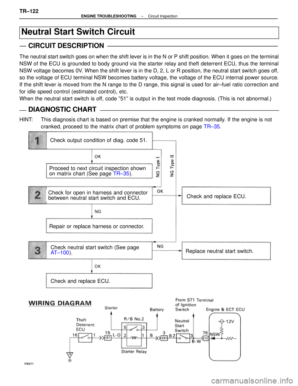
Neutral Start Switch Circuit
CIRCUIT DESCRIPTION
The neutral start switch goes on when the shift lever is in the N or P shif\
t position. When it goes on the terminal
NSW of the ECU is grounded to body ground via the starter relay and theft deterrent ECU\
, thus the terminal
NSW voltage becomes 0V. When the shift lever is in the D, 2, L or R position, the neutral start\
switch goes off,
so the voltage of ECU terminal NSW becomes battery voltage, the voltage of the ECU internal power source.
If the shift lever is moved from the N range to the D range, this signal\
is used for air±fuel ratio correction and
for idle speed control (estimated control), etc.
When the neutral start switch is off, code º51º is output in the test mode diagnosis. (This is not a\
bnormal.)
DIAGNOSTIC CHARTDIAGNOSTIC CHART
HINT: This diagnosis chart is based on premise that the engine is cranked norm\
ally. If the engine is notcranked, proceed to the matrix chart of problem symptoms on page TR±35.
Check output condition of diag. code 51.
Proceed to next circuit inspection shown
on matrix chart (See page TR±35).
Check for open in harness and connector
between neutral start switch and ECU.
Repair or replace harness or connector.
Check and replace ECU.
Check and replace ECU.
Replace neutral start switch.Check neutral start switch (See page
AT±100 ).
TR±122
±
ENGINE TROUBLESHOOTING Circuit Inspection
WhereEverybodyKnowsYourName
Page 3767 of 4087
OK
NG
Type I
NG
Type II
NG
OK
OKNG
INSPECTION PROCEDURE
1Check output condition of diag. code 51.
C
P(2) Connect terminals TE2 and E1 of TDCL.
(2) Turn ignition switch on.
(2) Crank the engine.
(2) Connect terminal TE1 and E1 of TDCL.
Check if diagnostic code ª51º is output when then shift
level is in the P and D shift positions.
Result:
Go to step 2.
Go to step 3.
Proceed to next circuit inspection shown on ma-
trix chart (See page TR±35).
2
Check for open in harness and connector between engine & ECT ECU and neutral \
start switch
(See page IN±27).
Check and replace engine & ECT ECU.
Repair or replace harness or connector.
3Check neutral start switch (See page AT±100).
Replace neutral start switch.
Check and replace engine & ECT ECU.
±
ENGINE TROUBLESHOOTING Circuit InspectionTR±123
WhereEverybodyKnowsYourName
Page 3768 of 4087
VALVE CLEARANCE ADJUSTING TOOL SETPage 1 of 1
The Valve Lifter Press has undergone two modifications that will improve service procedures
on UZ and VZ series engines.
1. Due to space limitations on these engines, the thickness of the valve li\
fter press jaws and its connecting rivet have been reduced. This reduction will allow pr\
oper
compression of the cam follower and spring without the tool slipping out\
of position.
2. The front jaw angle on the valve lifter press has also been modified. Th\
is change will allow easier installation of the tool between the camshaft and the follo\
wer, and also
provide improved leverage for the compression of the cam follower and sp\
ring.
The updated tool set, Part Number 09248±55020, supersedes your previous \
09248±55010
tool set. This new tool set will service all current Lexus engines.
SST'S/SSI'S
001
OCTOBER 11, 1991
ALL MODELS
WhereEverybodyKnowsYourName
Page 3811 of 4087

SERVICE HINTS FOR REFRIGERANT LEAK DETECTIONPage 2 of 3
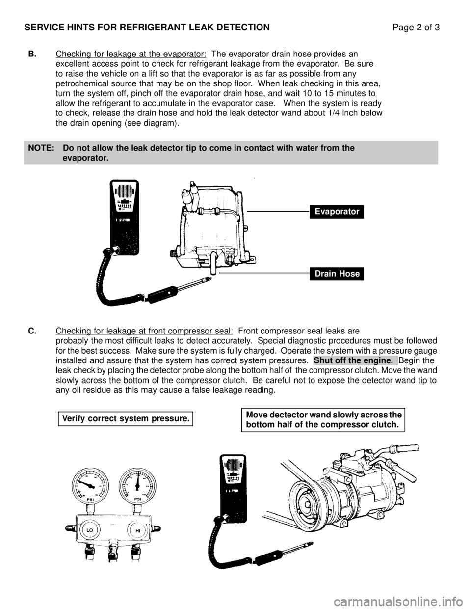
B.Checking for leakage at the evaporator: The evaporator drain hose provides an
excellent access point to check for refrigerant leakage from the evapora\
tor. Be sure
to raise the vehicle on a lift so that the evaporator is as far as possi\
ble from any
petrochemical source that may be on the shop floor. When leak checking in this area,
turn the system off, pinch off the evaporator drain hose, and wait 10 to 15 minutes to
allow the refrigerant to accumulate in the evaporator case. When the s\
ystem is ready
to check, release the drain hose and hold the leak detector wand about 1\
/4 inch below
the drain opening (see diagram).
NOTE: Do not allow the leak detector tip to come in contact with water from th\
e evaporator.
C. Checking for leakage at front compressor seal:
Front compressor seal leaks are
probably the most difficult leaks to detect accurately. Special diagnostic procedures must be followed
for the best success. Make sure the system is fully charged. Operate the \
system with a pressure gauge
installed and assure that the system has correct system pressures. Shut off the engine. Begin the
leak check by placing the detector probe along the bottom half of the compr\
essor clutch. Move the wand
slowly across the bottom of the compressor clutch. Be careful not to expose t\
he detector wand tip to
any oil residue as this may cause a false leakage reading.
Evaporator
Drain Hose
Verify correct system pressure. Move dectector wand slowly across the
bottom half of the compressor clutch.
WhereEverybodyKnowsYourName
Page 3821 of 4087

120
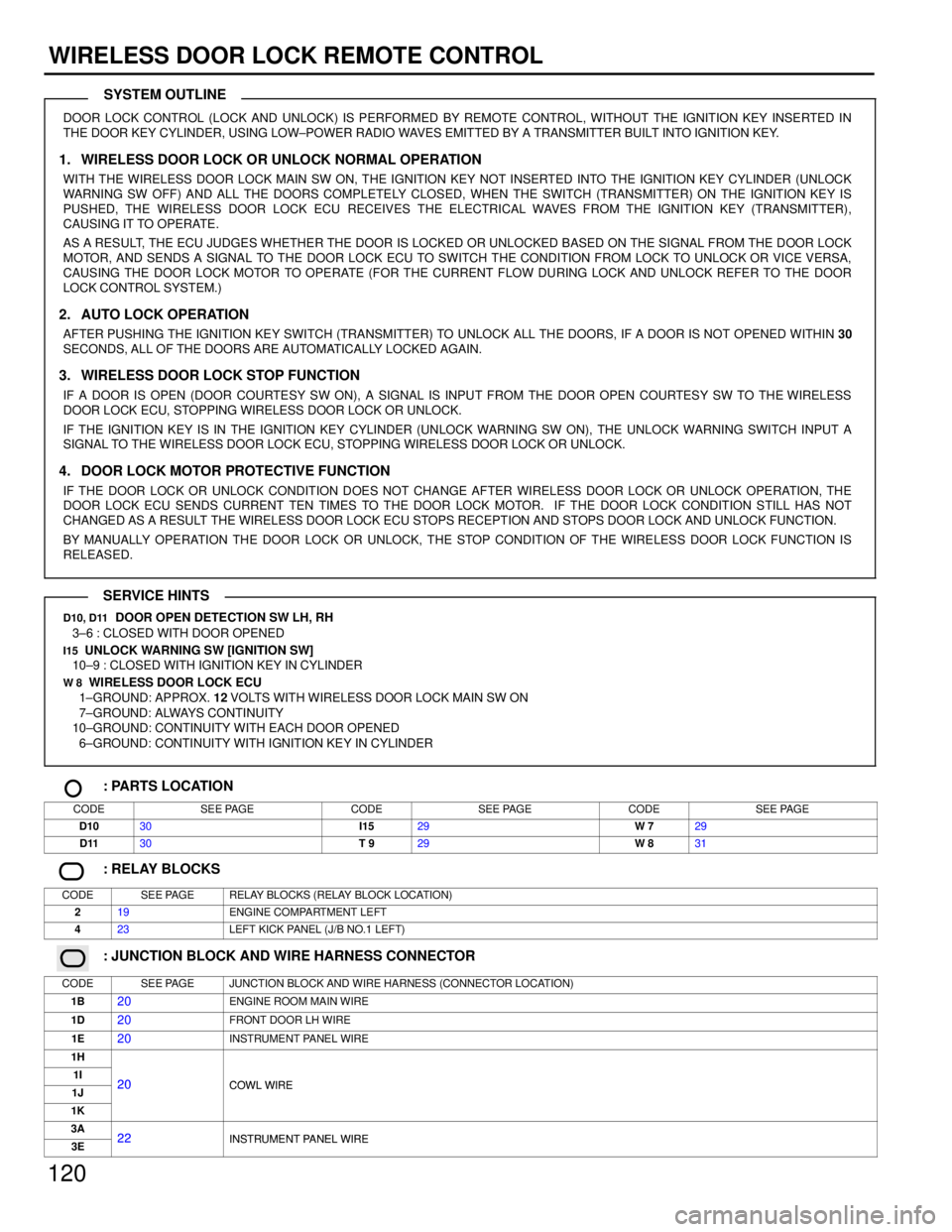
WIRELESS DOOR LOCK REMOTE CONTROL
DOOR LOCK CONTROL (LOCK AND UNLOCK) IS PERFORMED BY REMOTE CONTROL, WI\
THOUT THE IGNITION KEY INSERTED IN
THE DOOR KEY CYLINDER, USING LOW±POWER RADIO WAVES EMITTED BY A TRANSMITTER BUILT INTO IGNITION KEY.
1. WIRELESS DOOR LOCK OR UNLOCK NORMAL OPERATION
WITH THE WIRELESS DOOR LOCK MAIN SW ON, THE IGNITION KEY NOT INSERTED INTO THE IGNITION KEY CYLINDER (UNLOCK
WARNING SW OFF) AND ALL THE DOORS COMPLETELY CLOSED, WHEN THE SWITCH (TRANSMITTER) ON THE IGNITION KEY IS
PUSHED, THE WIRELESS DOOR LOCK ECU RECEIVES THE ELECTRICAL WAVES FROM THE IGNITION KEY (TRANSMITTER),
CAUSING IT TO OPERATE.
AS A RESULT, THE ECU JUDGES WHETHER THE DOOR IS LOCKED OR UNLOCKED BASED ON THE SIGNAL FROM THE DOOR LOCK
MOTOR, AND SENDS A SIGNAL TO THE DOOR LOCK ECU TO SWITCH THE CONDITION FROM LOCK TO UNLOCK OR VICE VERSA,
CAUSING THE DOOR LOCK MOTOR TO OPERATE (FOR THE CURRENT FLOW DURING LOCK AND UNLOCK REFER TO THE DOOR
LOCK CONTROL SYSTEM.)
2. AUTO LOCK OPERATION
AFTER PUSHING THE IGNITION KEY SWITCH (TRANSMITTER) TO UNLOCK ALL THE DOORS, IF A DOOR IS NOT OPENED WITHIN 30
SECONDS, ALL OF THE DOORS ARE AUTOMATICALLY LOCKED AGAIN.
3. WIRELESS DOOR LOCK STOP FUNCTION
IF A DOOR IS OPEN (DOOR COURTESY SW ON), A SIGNAL IS INPUT FROM THE DOOR OPEN COURTESY SW TO THE WIRELESS
DOOR LOCK ECU, STOPPING WIRELESS DOOR LOCK OR UNLOCK.
IF THE IGNITION KEY IS IN THE IGNITION KEY CYLINDER (UNLOCK WARNING SW ON), THE UNLOCK WARNING SWITCH INPUT A
SIGNAL TO THE WIRELESS DOOR LOCK ECU, STOPPING WIRELESS DOOR LOCK OR UNLOCK.
4. DOOR LOCK MOTOR PROTECTIVE FUNCTION
IF THE DOOR LOCK OR UNLOCK CONDITION DOES NOT CHANGE AFTER WIRELESS DOOR L\
OCK OR UNLOCK OPERATION, THE
DOOR LOCK ECU SENDS CURRENT TEN TIMES TO THE DOOR LOCK MOTOR. IF THE DOOR LOCK CONDITION STILL HAS NOT
CHANGED AS A RESULT THE WIRELESS DOOR LOCK ECU STOPS RECEPTION AND STOPS DOOR LOCK AND UNLOCK FUNCTION.
BY MANUALLY OPERATION THE DOOR LOCK OR UNLOCK, THE STOP CONDITION OF THE WIRELESS DOOR LOCK FUNCTION IS
RELEASED.
D10, D11 DOOR OPEN DETECTION SW LH, RH
3±6 : CLOSED WITH DOOR OPENED
I15 UNLOCK WARNING SW [IGNITION SW]
10±9 : CLOSED WITH IGNITION KEY IN CYLINDER
W 8 WIRELESS DOOR LOCK ECU
1±GROUND: APPROX. 12 VOLTS WITH WIRELESS DOOR LOCK MAIN SW ON
7±GROUND: ALWAYS CONTINUITY
10±GROUND: CONTINUITY WITH EACH DOOR OPENED
6±GROUND: CONTINUITY WITH IGNITION KEY IN CYLINDER
: PARTS LOCATION
CODESEE PAGECODESEE PAGECODESEE PAGE
D1030I1529W 729
D1130T 929W 831
: RELAY BLOCKS
CODESEE PAGERELAY BLOCKS (RELAY BLOCK LOCATION)
219ENGINE COMPARTMENT LEFT
423LEFT KICK PANEL (J/B NO.1 LEFT)
: JUNCTION BLOCK AND WIRE HARNESS CONNECTOR
CODESEE PAGEJUNCTION BLOCK AND WIRE HARNESS (CONNECTOR LOCATION)
1B20ENGINE ROOM MAIN WIRE
1D20FRONT DOOR LH WIRE
1E20INSTRUMENT PANEL WIRE
1H
1I20COWL WIRE1J20COWL WIRE
1K
3A22INSTRUMENT PANEL WIRE3E22INSTRUMENT PANEL WIRE
SYSTEM OUTLINE
SERVICE HINTS
WhereEverybodyKnowsYourName
Page 3823 of 4087
201
WIPER AND WASHER
: PARTS LOCATION
CODESEE PAGECODESEE PAGECODESEE PAGE
C15B28W 227
C16A28W 527
: JUNCTION BLOCK AND WIRE HARNESS CONNECTOR
CODESEE PAGEJUNCTION BLOCK AND WIRE HARNESS (CONNECTOR LOCATION)
1H
1J20COWL WIRE
1K
: CONNECTOR JOINING WIRE HARNESS AND WIRE HARNESS
CODESEE PAGEJOINING WIRE HARNESS AND WIRE HARNESS (CONNECTOR LOCATION)
IE136ENGINE ROOM MAIN WIRE AND COWL WIRE (R/B NO. 4)
: GROUND POINTS
CODESEE PAGEGROUND POINTS LOCATION
IF36LEFT KICK PANEL
: SPLICE POINTS
CODESEE PAGEWIRE HARNESS WITH SPLICE POINTSCODESEE PAGEWIRE HARNESS WITH SPLICE POINTS
I 738COWL WIRE
WhereEverybodyKnowsYourName
Page 3826 of 4087

15
ABBREVIATIONS
DISCONNECTION AND CONNECTION OF BOLT
TYPE CONNECTORS
For engine and ECT ECU in this vehicle, connectors are used
which require a bolt built into the connector to be screwed down to
securely connect the connector.
1. Disconnect the connectorAfter completely loosening the bolt, the two parts of the
connector can be separated.
NOTICE:
Do not pull the wire harness when disconnecting the
connector.
2. Connect the connector
NOTICE:
Before connecting the connector, always check that the
terminals are not bent or damaged.
(a) Match the guide section of the male connectorcorrectly with the female connector, then press them
together.
(b) Tighten the bolt. Make sure the connectors are completely connected,
by tightening the bolt until there is a clearance of less
than 1 mm (0.04 in.) between the bottom of male
connector and the end of female connector.
ABBREVIATIONS
The following abbreviations are used in this manual.
A/C = Air Conditioning O/D = Overdrive
ABS = Anti±Lock Brake System R/B = Relay Block
A/T = Automatic Transmission RH = Right±Hand
CB = Circuit Breaker SRS = Supplement Restraint System
COMB. = Combination SW = Switch
ECT = Electronic Controlled Transmission TDCL = Total Diagnostic Communication Link
ECU = Electronic Control Unit TEMP. = Temperature
EGR = Exhaust Gas Recirculation TRAC = Traction Control
FL = Fusible Link VSV = Vacuum Switching Valve
ISC = Idle Speed Control W/ = With
J/B = Junction Block W/O = Without
LH = Left-Hand
* The titles given inside the components are the names of the terminals (ter\
minal codes) and are not treatedas being abbreviations.
WhereEverybodyKnowsYourName