Page 646 of 4087
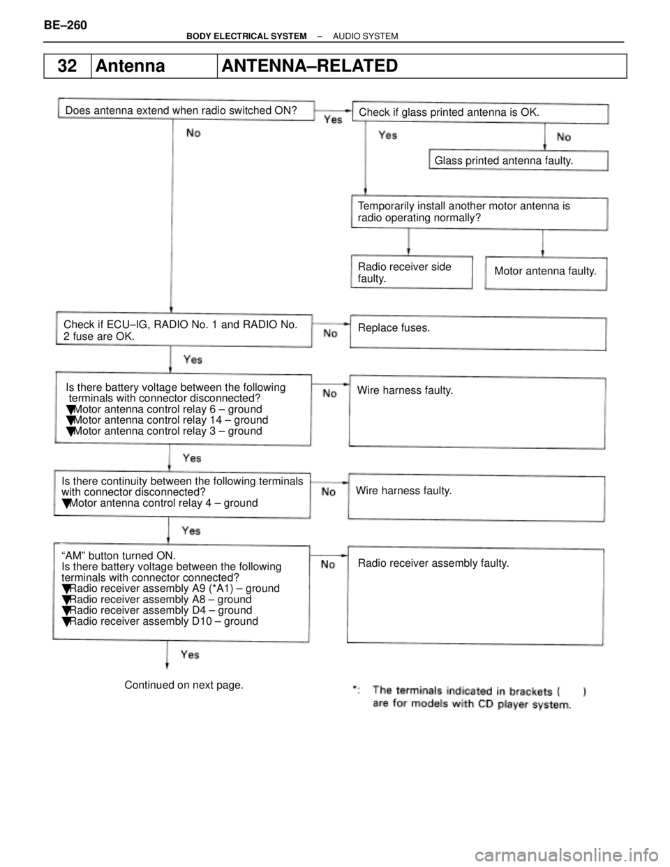
32AntennaANTENNA±RELATED
Does antenna extend when radio switched ON?Wire harness faulty.
Is there battery voltage between the following
terminals with connector disconnected?
�
Motor antenna control relay 6 ± ground
� Motor antenna control relay 14 ± ground
� Motor antenna control relay 3 ± ground
Wire harness faulty.Replace fuses.
Radio receiver assembly faulty.
Check if ECU±IG, RADIO No. 1 and RADIO No.
2 fuse are OK.
ªAMº button turned ON.
Is there battery voltage between the following
terminals with connector connected?
� Radio receiver assembly A9 (*A1) ± ground
� Radio receiver assembly A8 ± ground
� Radio receiver assembly D4 ± ground
� Radio receiver assembly D10 ± ground Radio receiver side
faulty.
Motor antenna faulty.
Temporarily install another motor antenna is
radio operating normally?
Glass printed antenna faulty.
Check if glass printed antenna is OK.
Is there continuity between the following terminals
with connector disconnected?
� Motor antenna control relay 4 ± ground
Continued on next page.
BE±260±
BODY ELECTRICAL SYSTEM AUDIO SYSTEM
WhereEverybodyKnowsYourName
Page 814 of 4087

Description
The power source supplies power to each of the vehicle's electrical devices. It is composed of the battery, fuses
and relays, which are located centrally at relay block No. 2 and relay block No. 6 i\
n the engine compartment
and junction block No. 1 relay block No. 4 and relay block No. 5 in the \
cabin near the driver's feet.
Related systems for each Fuse
No.Part NameRelated Systems or Parts
1IGN � Charging System � AIR±BAG System1IGN � Engine
2ST � Starter
3WIPER � Wiper and Washer System
4HTR � Defogger System � A/C System
5ENGINE � Charging System
6RADIO NO. 2 � Audio System � Power Mirror System
� Cigarette Lighter � A/C System
7CIG � Combination Meter System � AIR±BAG System7CIG � Shift Lock System � Theft Deterrent System
� TEL System
8STOP � Stop Light System � Cruise Control System
9TURN � Turn Signal and Hazard
Warning Light System � Cornnering Light System
10MIR HTR � Mirror Heater System
11PANEL � Illumination Light System
12ECU±B � Combination Meter System � AIR±BAG System
� Combination Meter System � ECT System
13GAUGE � Back±Up Light � Transmission Indicator
� Light Failare Sensor � ABS and TRAC
� Power Seat System � Door Lock Control System
� TEL System � Shift Lock System
14ECU±IG � Radiator Fan � Auto Antenna
� Electric Tension Reducer System � Power Steering
� Auto±Tilt away Steering � Cruise Control System
15TAIL � Taillight System � Side Marker15TAIL � Clearance Light
16DOOR � Power Seat System � Luggage Door Opener16DOOR � Door Lock Control System � Fuel Lid Opener System
17IG SWUpstream of ECU±IG, ENGINE, WIP, HTR, TURN, GAUGE, and ST Fuse
18PWR � Power Window System � Sliding Roof System
19ABS NO. 1 � ABS and TRAC
20AM1Upstream of MIR HTR, TAIL, PANEL, STOP, ECUA±B, DOOR and PWR Fuse
21ALTUpstream of DEF, HTR, AM1, and ABS No. 1 Fuse
BE±18±
BODY ELECTRICAL SYSTEM Power Source
WhereEverybodyKnowsYourName
Page 1137 of 4087
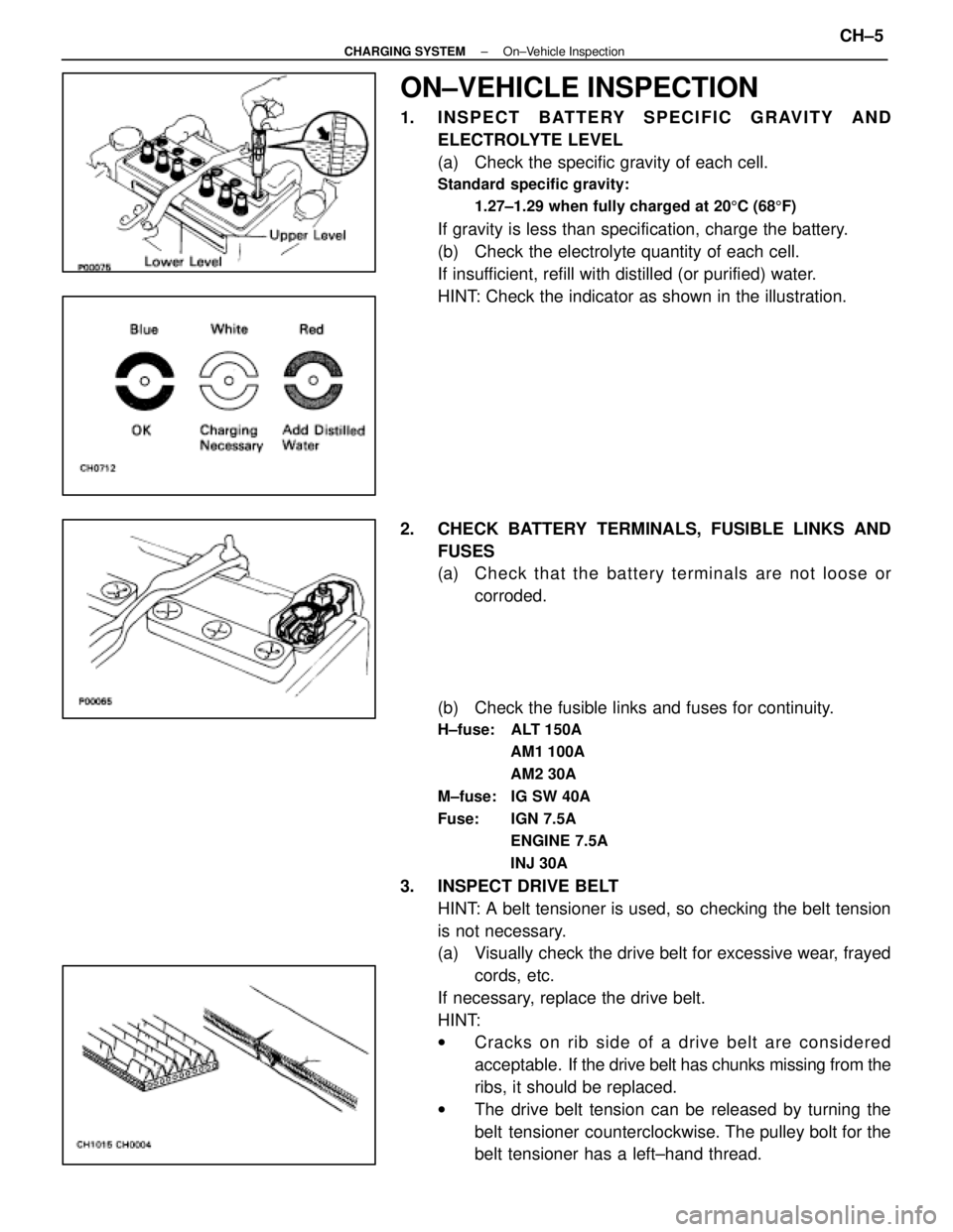
ON±VEHICLE INSPECTION
1. INSPECT BATTERY SPECIFIC GRAVITY ANDELECTROLYTE LEVEL
(a) Check the specific gravity of each cell.
Standard specific gravity:
1.27±1.29 when fully charged at 20 5C (68 5F)
If gravity is less than specification, charge the battery.
(b) Check the electrolyte quantity of each cell.
If insufficient, refill with distilled (or purified) water.
HINT: Check the indicator as shown in the illustration.
2. CHECK BATTERY TERMINALS, FUSIBLE LINKS AND FUSES
(a) Check that the battery terminals are not loose orcorroded.
(b) Check the fusible links and fuses for continuity.
H±fuse: ALT 150A AM1 100A
AM2 30A
M±fuse: IG SW 40A
Fuse: IGN 7.5A ENGINE 7.5A
INJ 30A
3. INSPECT DRIVE BELTHINT: A belt tensioner is used, so checking the belt tension
is not necessary.
(a) Visually check the drive belt for excessive wear, frayedcords, etc.
If necessary, replace the drive belt.
HINT:
w Cracks on rib side of a drive belt are considered
acceptable. If the drive belt has chunks missing from the
ribs, it should be replaced.
w The drive belt tension can be released by turning the
belt tensioner counterclockwise. The pulley bolt for the
belt tensioner has a left±hand thread.
±
CHARGING SYSTEM On±Vehicle InspectionCH±5
WhereEverybodyKnowsYourName
Page 1387 of 4087
wIf the vehicle has been running, wait 5 minutes or more
after the vehicle stops before measuring the battery
voltage.
If the voltage is less than specification, charge the battery.
HINT: Check the indicator as shown in the illustration.
1. C H E C K B AT T E RY S P E C I F I C G R AV I T Y A N D ELECTROLYTE LEVEL
2. CHECK BATTERY TERMINALS AND FUSES
(a) Check that the battery terminals are not loose or corroded.
(b) Check the fuses for continuity.
EG3F9±01
AIR FILTER INSPECTION AND
CLEANING
1. REMOVE AIR FILTER
(a) Open the air cleaner cap.
(b) Remove the air filter.
±
1UZ±FE ENGINE ENGINE MECHANICALEG±11
WhereEverybodyKnowsYourName
Page 2029 of 4087
If there is no pressure, check the following parts:
wFuses
w EFI main relay
w Fuel pump ECU
w Fuel pump
w Engine (& ECT) ECU
w Wiring connections
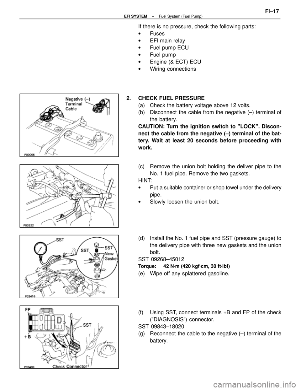
2. CHECK FUEL PRESSURE (a) Check the battery voltage above 12 volts.
(b) Disconnect the cable from the negative (±) terminal ofthe battery.
CAUTION: Turn the ignition switch to ºLOCKº. Discon-
nect the cable from the negative (±) terminal of the bat-
tery. Wait at least 20 seconds before proceeding with
work.
(c) Remove the union bolt holding the deliver pipe to the No. 1 fuel pipe. Remove the two gaskets.
HINT:
w Put a suitable container or shop towel under the delivery
pipe.
w Slowly loosen the union bolt.
(d) Install the No. 1 fuel pipe and SST (pressure gauge) to the delivery pipe with three new gaskets and the union
bolt.
SST 09268±45012
Torque: 42 N Vm (420 kgf Vcm, 30 ft Vlbf)
(e) Wipe off any splattered gasoline.
(f) Using SST, connect terminals +B and FP of the check
(ºDIAGNOSISº) connector.
SST 09843±18020
(g) Reconnect the cable to the negative (±) terminal of the battery.
±
EFI SYSTEM Fuel System (Fuel Pump)FI±17
WhereEverybodyKnowsYourName
Page 2037 of 4087
If there is no pressure, check the following parts:w Fuses
w EFI main relay
w Fuel pump ECU
w Fuel pump
w Engine & ECT ECU
w Wiring connections
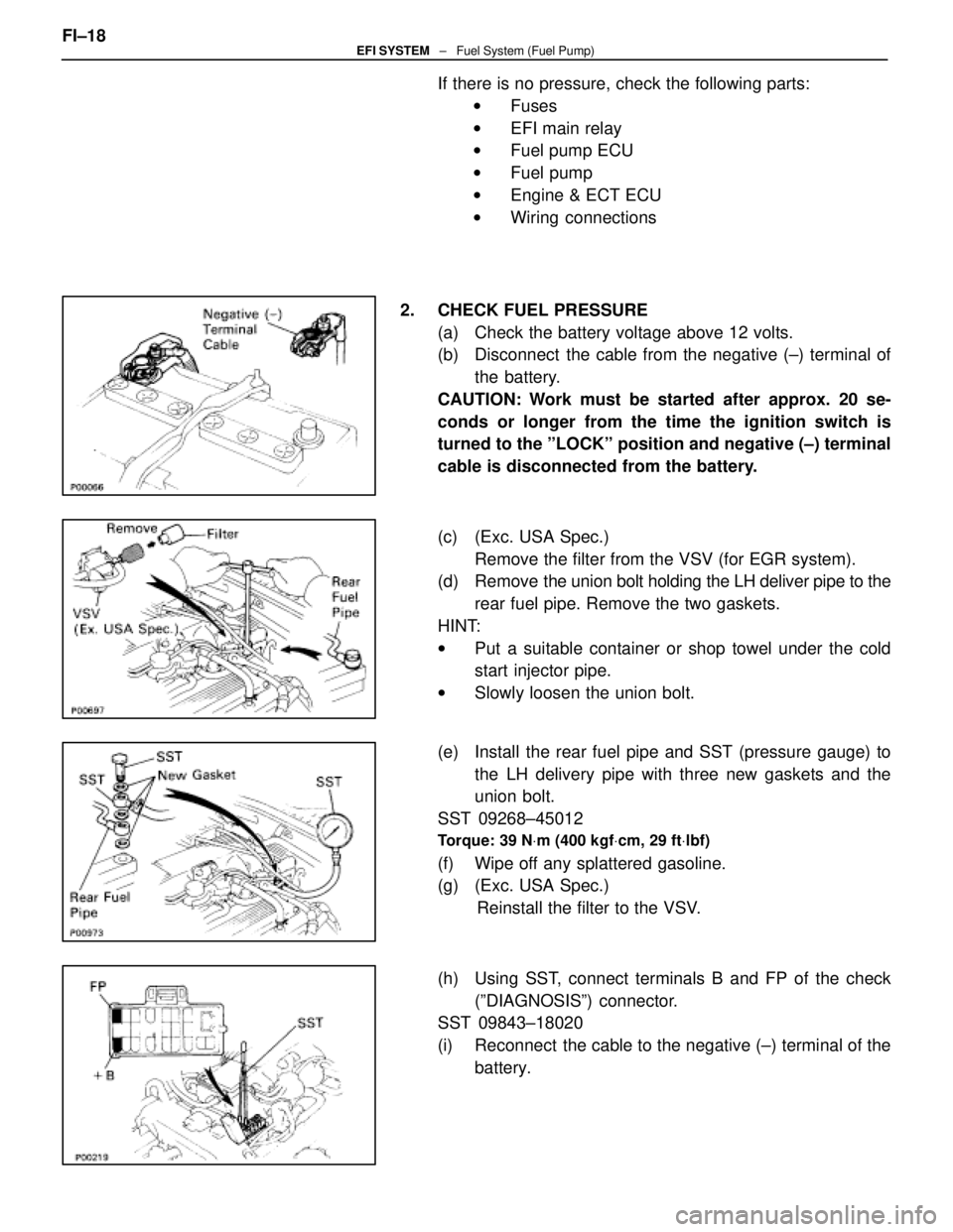
2. CHECK FUEL PRESSURE (a) Check the battery voltage above 12 volts.
(b) Disconnect the cable from the negative (±) terminal ofthe battery.
CAUTION: Work must be started after approx. 20 se-
conds or longer from the time the ignition switch is
turned to the ºLOCKº position and negative (±) terminal
cable is disconnected from the battery.
(c) (Exc. USA Spec.) Remove the filter from the VSV (for EGR system).
(d) Remove the union bolt holding the LH deliver pipe to the
rear fuel pipe. Remove the two gaskets.
HINT:
w Put a suitable container or shop towel under the cold
start injector pipe.
w Slowly loosen the union bolt.
(e) Install the rear fuel pipe and SST (pressure gauge) to the LH delivery pipe with three new gaskets and the
union bolt.
SST 09268±45012
Torque: 39 N Vm (400 kgf Vcm, 29 ft Vlbf)
(f) Wipe off any splattered gasoline.
(g) (Exc. USA Spec.)
Reinstall the filter to the VSV.
(h) Using SST, connect terminals B and FP of the check (ºDIAGNOSISº) connector.
SST 09843±18020
(i) Reconnect the cable to the negative (±) terminal of the
battery.
FI±18
EFI SYSTEM
± Fuel System (Fuel Pump)
WhereEverybodyKnowsYourName
Page 2398 of 4087
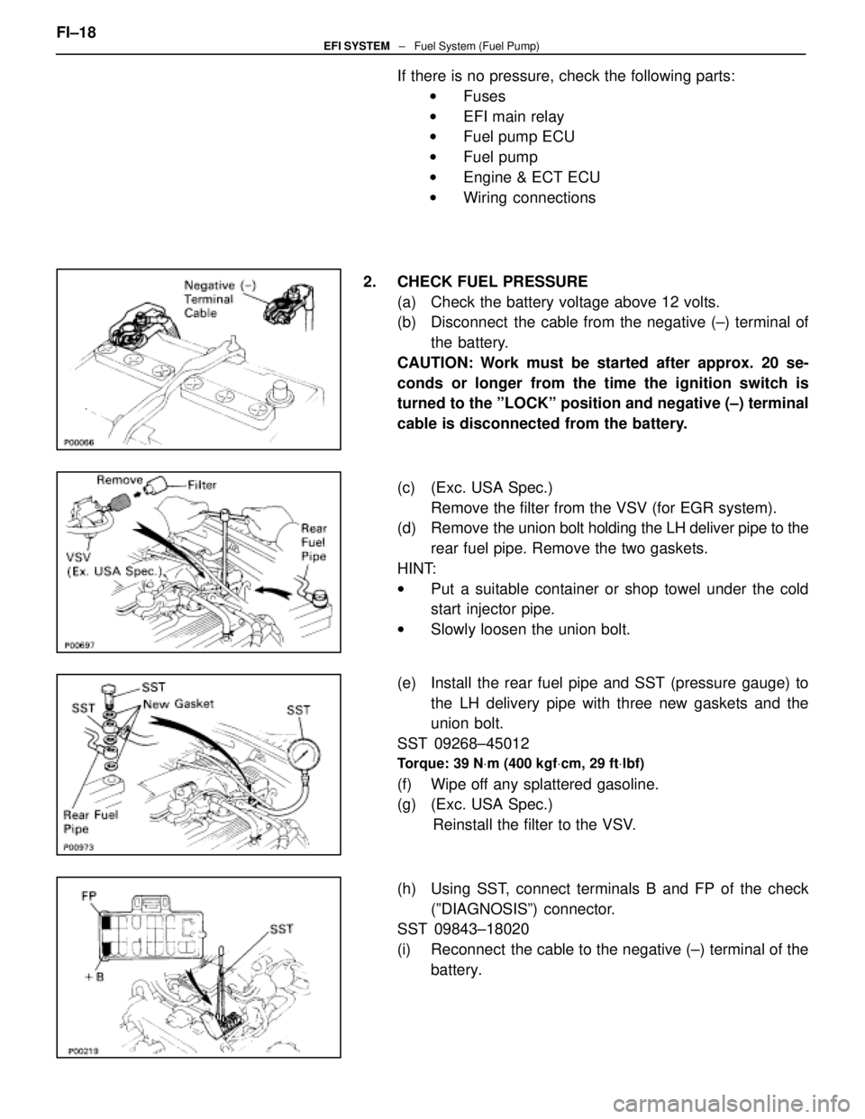
If there is no pressure, check the following parts:w Fuses
w EFI main relay
w Fuel pump ECU
w Fuel pump
w Engine & ECT ECU
w Wiring connections
2. CHECK FUEL PRESSURE (a) Check the battery voltage above 12 volts.
(b) Disconnect the cable from the negative (±) terminal ofthe battery.
CAUTION: Work must be started after approx. 20 se-
conds or longer from the time the ignition switch is
turned to the ºLOCKº position and negative (±) terminal
cable is disconnected from the battery.
(c) (Exc. USA Spec.) Remove the filter from the VSV (for EGR system).
(d) Remove the union bolt holding the LH deliver pipe to the
rear fuel pipe. Remove the two gaskets.
HINT:
w Put a suitable container or shop towel under the cold
start injector pipe.
w Slowly loosen the union bolt.
(e) Install the rear fuel pipe and SST (pressure gauge) to the LH delivery pipe with three new gaskets and the
union bolt.
SST 09268±45012
Torque: 39 N Vm (400 kgf Vcm, 29 ft Vlbf)
(f) Wipe off any splattered gasoline.
(g) (Exc. USA Spec.)
Reinstall the filter to the VSV.
(h) Using SST, connect terminals B and FP of the check (ºDIAGNOSISº) connector.
SST 09843±18020
(i) Reconnect the cable to the negative (±) terminal of the
battery.
FI±18
EFI SYSTEM
± Fuel System (Fuel Pump)
WhereEverybodyKnowsYourName
Page 2769 of 4087
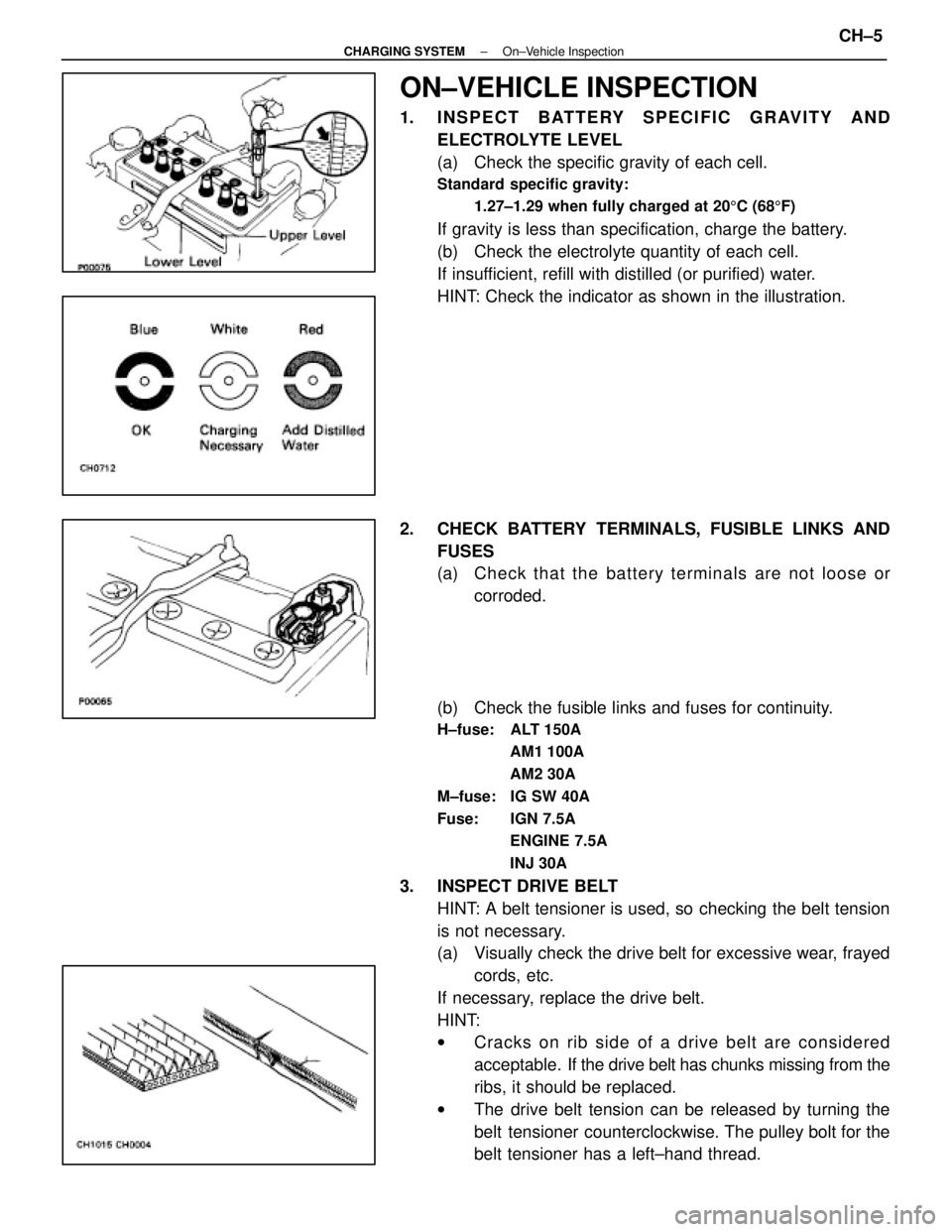
ON±VEHICLE INSPECTION
1. INSPECT BATTERY SPECIFIC GRAVITY ANDELECTROLYTE LEVEL
(a) Check the specific gravity of each cell.
Standard specific gravity:
1.27±1.29 when fully charged at 20 5C (68 5F)
If gravity is less than specification, charge the battery.
(b) Check the electrolyte quantity of each cell.
If insufficient, refill with distilled (or purified) water.
HINT: Check the indicator as shown in the illustration.
2. CHECK BATTERY TERMINALS, FUSIBLE LINKS AND FUSES
(a) Check that the battery terminals are not loose orcorroded.
(b) Check the fusible links and fuses for continuity.
H±fuse: ALT 150A AM1 100A
AM2 30A
M±fuse: IG SW 40A
Fuse: IGN 7.5A ENGINE 7.5A
INJ 30A
3. INSPECT DRIVE BELTHINT: A belt tensioner is used, so checking the belt tension
is not necessary.
(a) Visually check the drive belt for excessive wear, frayedcords, etc.
If necessary, replace the drive belt.
HINT:
w Cracks on rib side of a drive belt are considered
acceptable. If the drive belt has chunks missing from the
ribs, it should be replaced.
w The drive belt tension can be released by turning the
belt tensioner counterclockwise. The pulley bolt for the
belt tensioner has a left±hand thread.
±
CHARGING SYSTEM On±Vehicle InspectionCH±5
WhereEverybodyKnowsYourName