Page 385 of 4087
4. CONNECT SOLENOID VALVE CONNECTORS
5. INSTALL OIL STRAINER AND GASKETSInstall the oil strainer and torque the 3 bolts.
Torque: 10 N Vm (100 kgf Vcm, 7 ft Vlbf)
6. INSTALL OIL PAN
(a) Install the 4 magnets in the indentations of the oil pan, as
shown in the illustration.
(b) Remove any FIPG material and be careful not to drop oil on the contacting surfaces of the transmission case and oil pan.
(c) Apply FIPG to the oil pan, as shown in the illustration.
FIPG:
Part No. 08826±00090, THREE BOND 1281 or equivalent
(d) Install the oil pan to the transmission case and torque the 19bolts.
Torque: 7.4 N Vm (75 kgf Vcm, 65 in. Vlbf)
7. INSTALL FRONT EXHAUST PIPE
(See page EG±204)
8. CHECK FLUID LEVEL
AT±22
±
A304E (1UZ±FE) AUTOMATIC TRANSMISSION VALVE BODY
WhereEverybodyKnowsYourName
Page 389 of 4087
INSTALLATION MAIN POINTS
AT00L±01
1. CHECK TORQUE CONVERTER CLUTCH INSTALLATIONUsing calipers and a straight edge, measure from the
installed surface of the torque converter clutch to the front
surface of the transmission housing.
Correct distance:
17.1 mm (0.673 in.)
If the distance is less than the standard, check for an improp-
er installation.
2. LIFT ENGINE FRONT SIDE
3. INSTALL THROTTLE CABLE
4. ADJUST THROTTLE CABLE (See page AT±48)
5. FILL TRANSMISSION WITH ATF AND CHECK FLUID LEVEL
(See page AT±47)
NOTICE: Do not overfill.
Fluid type:
ATF Type T±II or equivalent
6. INSTALL PROPELLER SHAFT(See page PR±12 to PR±14 )
7. INSTALL EXHAUST PIPE
(See page EG±204)
AT±26
±
A304E (1UZ±FE) AUTOMATIC TRANSMISSION ASSEMBLY REMOVAL AND INSTALLATION
WhereEverybodyKnowsYourName
Page 1326 of 4087
SERVICE SPECIFICATIONS
SPECIFICATIONS
VSV (For EVAP) Resistance30±34 �
VSV (For EGR)Resistance33±39 �
TORQUE SPECIFICATIONS
Part tightenedN mkgf cmftVlbf
VSV for EGR X Intake manifold18185 13
EGR valve X Intake manifold18185 13
EGR valve X EGR Pipe64650 47
Catalytic converter (Front) X Exhaust manifold62630 46
Catalytic converter (Front) X Front Exhaust pipe43440 32
Front exhaust pipe X Center exhaust pipe43440 32
Sub±oxygen sensor X Front exhaust pipe1818013
EC±20±
EMISSION CONTROL SYSTEMS Service Specifications
WhereEverybodyKnowsYourName
Page 1328 of 4087
INSPECTION OF EXHAUST PIPE
ASSEMBLY
1. CHECK CONNECTIONS FOR LOOSENESS OR DAMAGE
2. CHECK CLAMPS FOR WEAKNESS, CRACKS OR
DAMAGE
INSPECTION OF CATALYTIC
CONVERTERS
CHECK FOR DENTS OR DAMAGE If any part of protector is damaged or dented to the extent that
it contacts the converter, repair or replace it.
INSPECTION OF HEAT INSULATORS
1. CHECK HEAT INSULATOR FOR DAMAGE
2. CHECK FOR ADEQUATE CLEARANCE BETWEEN
CATALYTIC CONVERTER AND HEAT INSULATOR
COMPONENTS FOR REPLACEMENT OF CATALYTIC CONVERTERS
±
EMISSION CONTROL SYSTEMS Three±Way Catalyst (TWC) SystemEC±27
WhereEverybodyKnowsYourName
Page 1329 of 4087

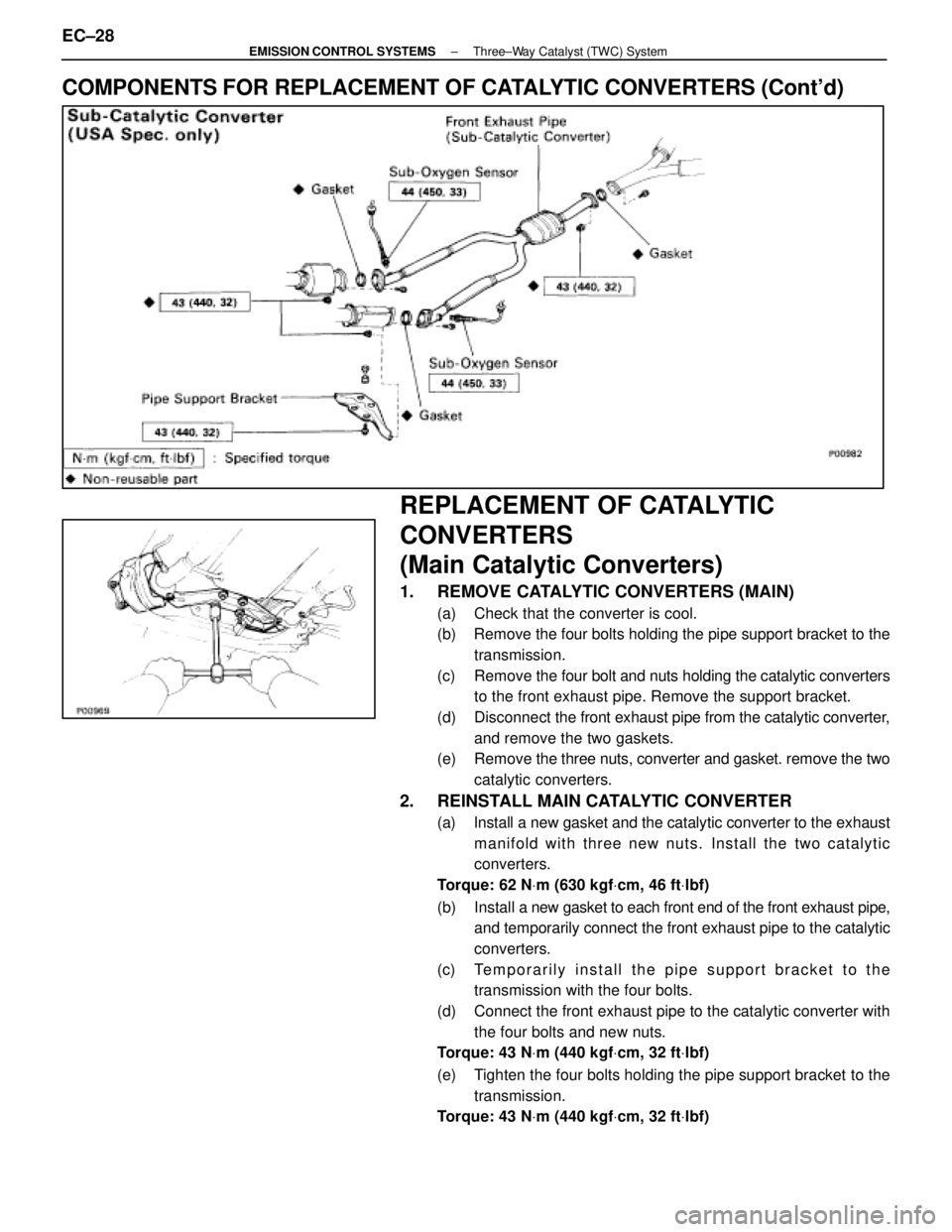
COMPONENTS FOR REPLACEMENT OF CATALYTIC CONVERTERS (Cont'd)
REPLACEMENT OF CATALYTIC
CONVERTERS
(Main Catalytic Converters)
1. REMOVE CATALYTIC CONVERTERS (MAIN)
(a) Check that the converter is cool.
(b) Remove the four bolts holding the pipe support bracket to thetransmission.
(c) Remove the four bolt and nuts holding the catalytic converters
to the front exhaust pipe. Remove the support bracket.
(d) Disconnect the front exhaust pipe from the catalytic converter,
and remove the two gaskets.
(e) Remove the three nuts, converter and gasket. remove the two
catalytic converters.
2. REINSTALL MAIN CATALYTIC CONVERTER
(a) Install a new gasket and the catalytic converter to the exhaust manifold with three new nuts. Install the two catalytic
converters.
Torque: 62 N Vm (630 kgf Vcm, 46 ft Vlbf)
(b) Install a new gasket to each front end of the front exhaust pipe,
and temporarily connect the front exhaust pipe to the catalytic
converters.
(c) Temporarily install the pipe support bracket to the transmission with the four bolts.
(d) Connect the front exhaust pipe to the catalytic converter with the four bolts and new nuts.
Torque: 43 N Vm (440 kgf Vcm, 32 ft Vlbf)
(e) Tighten the four bolts holding the pipe support bracket to the transmission.
Torque: 43 N Vm (440 kgf Vcm, 32 ft Vlbf)
EC±28±
EMISSION CONTROL SYSTEMS Three±Way Catalyst (TWC) System
WhereEverybodyKnowsYourName
Page 1330 of 4087

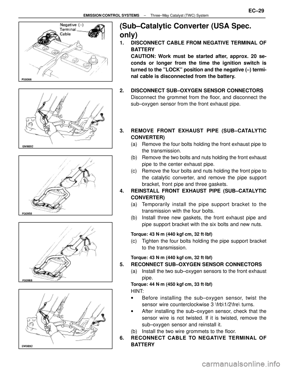
(Sub±Catalytic Converter (USA Spec.
only)
1. DISCONNECT CABLE FROM NEGATIVE TERMINAL OFBATTERY
CAUTION: Work must be started after, approx. 20 se-
conds or longer from the time the ignition switch is
turned to the ºLOCKº position and the negative (±) termi-
nal cable is disconnected from the battery.
2. DISCONNECT SUB±OXYGEN SENSOR CONNECTORS Disconnect the grommet from the floor, and disconnect the
sub±oxygen sensor from the front exhaust pipe.
3. REMOVE FRONT EXHAUST PIPE (SUB±CATALYTIC CONVERTER)
(a) Remove the four bolts holding the front exhaust pipe tothe transmission.
(b) Remove the two bolts and nuts holding the front exhaust
pipe to the center exhaust pipe.
(c) Remove the four bolts and nuts holding the front pipe to the catalytic converter, and remove the pipe support
bracket, front pipe and three gaskets.
4. REINSTALL FRONT EXHAUST PIPE (SUB±CATALYTIC CONVERTER)
(a) Temporarily install the pipe support bracket to thetransmission with the four bolts.
(b) Install three new gaskets, the front exhaust pipe and pipe support bracket with the six bolts and new nuts.
Torque: 43 N Vm (440 kgf Vcm, 32 ft Vlbf)
(c) Tighten the four bolts holding the pipe support bracket
to the transmission.
Torque: 43 N Vm (440 kgf Vcm, 32 ft Vlbf)
5. RECONNECT SUB±OXYGEN SENSOR CONNECTORS
(a) Install the two sub±oxygen sensors to the front exhaustpipe.
Torque: 44 N Vm (450 kgf Vcm, 33 ft Vlbf)
HINT:
w Before installing the s ub±oxygen sensor, twist the
sensor wire counterclockwise 3 \frb\1/2\fre turns.
w After installing the sub±oxygen sensor, check that the
sensor wire is not twisted. If it is twisted, remove the
sub±oxygen sensor and reinstall it.
(b) Install the two wire grommets to the floor.
6. RECONNECT CABLE TO NEGATIVE TERMINAL OF
BATTERY
±
EMISSION CONTROL SYSTEMS Three±Way Catalyst (TWC) SystemEC±29
WhereEverybodyKnowsYourName
Page 1331 of 4087
SERVICE SPECIFICATIONS
SERVICE DATA
VSVResistance30±34 �
for EVAP
VSVResistance33±39 �
for EGR
EGR valveResistance19.9±23.4 �
(CALIF. only)
TORQUE SPECIFICATIONS
Part tightenedNVmkgf Vcmft Vlbf
VSV for EGR X Air intake chamber (Exc. USA Spec.)1818513
EGR valve X Air intake chamber18185 13
Catalytic converter (Main) X Exhaust manifold62630 46
Catalytic converter (Main) X Front exhaust pipe43440 32
Front exhaust pipe support bracket X Transmission43440 32
Front exhaust pipe X Center exhaust pipe43440 32
Main oxygen sensor X Front exhaust pipe4445033
EC±30±
EMISSION CONTROL SYSTEMS Servuce Specifications
WhereEverybodyKnowsYourName
Page 1333 of 4087

DESCRIPTION
The emission control systems are installed to reduce the amount of HC, CO, \
and NOx emitted from the en-
gine, and to also prevent the release of evaporated fuel from the gasoline ta\
nk and prevent atmospheric release
of blow±by gas. The system consists of the PCV, EVAP, EGR and TWC.
The function of each system is shown in the following table.
��������������� ���������������
System
��������� ���������
Abbreviation
�������������� ��������������
Purpose��������������� ���������������
Positive crankcase ventilation
��������� ���������
PCV
�������������� ��������������
Reduces blow±by gas (HC)��������������� ���������������
Fuel evaporative emission control
��������� ���������
EVAP
�������������� ��������������
Reduces evaporative HC��������������� ���������������
Exhaust gas recirculation
��������� ���������
EGR
�������������� ��������������
Reduces NOx��������������� ���������������
Three±way catalyst
��������� ���������
TWC
�������������� ��������������
Reduces HC, CO, and NOx��������������� ���������������
Electronic fuel injection*
��������� ���������
EFI
�������������� ��������������
Regulates all engine conditions for��������������� ������������������������ ����������������������� ��������������
reduction of exhaust emissions.
Remarks: * For inspection and repair of the EFI system, refer to EFI sec\
tion.
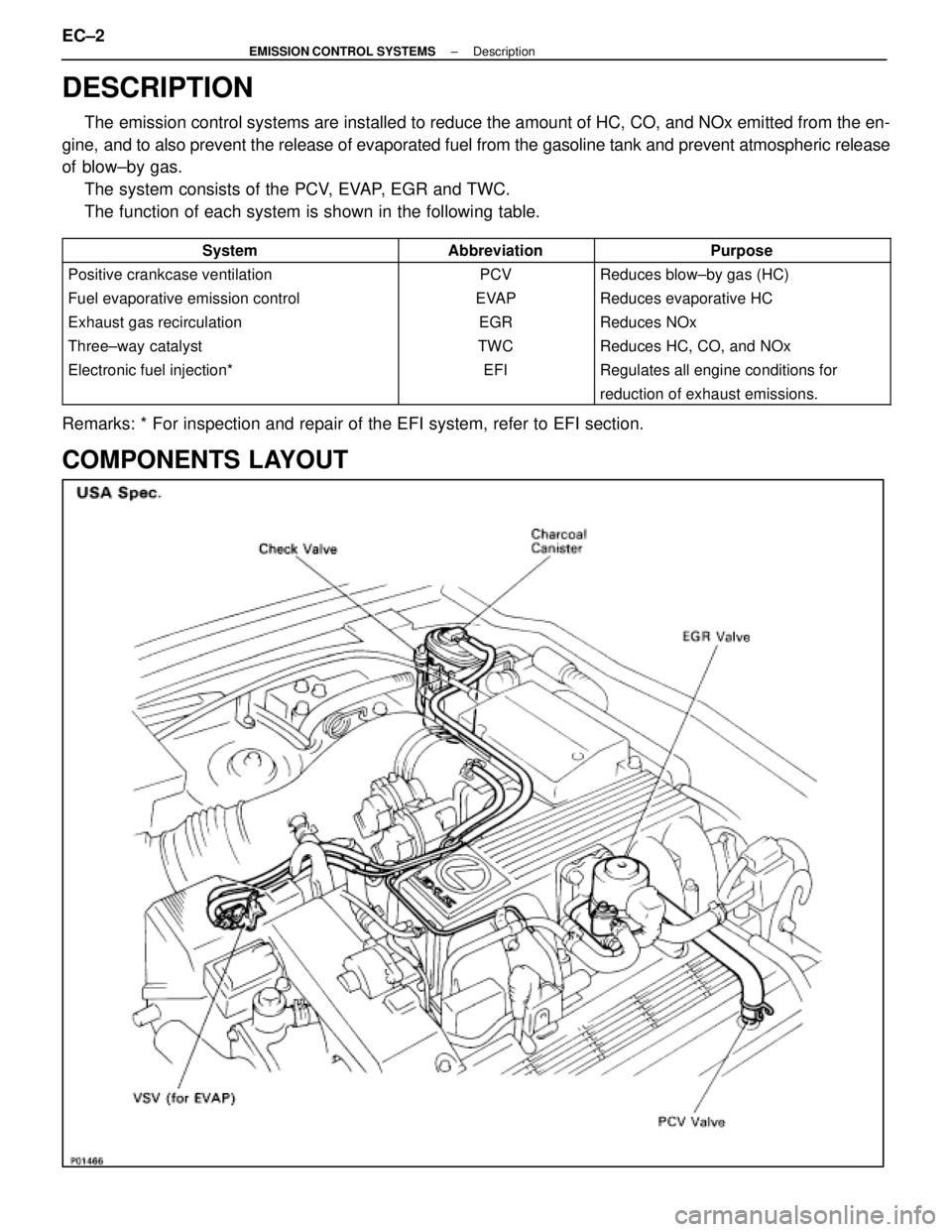
COMPONENTS LAYOUT
EC±2±
EMISSION CONTROL SYSTEMS Description
WhereEverybodyKnowsYourName