Page 56 of 4087

USE OF MANIFOLD GAUGE SET
INSTALLATION OF MANIFOLD GAUGE
SET
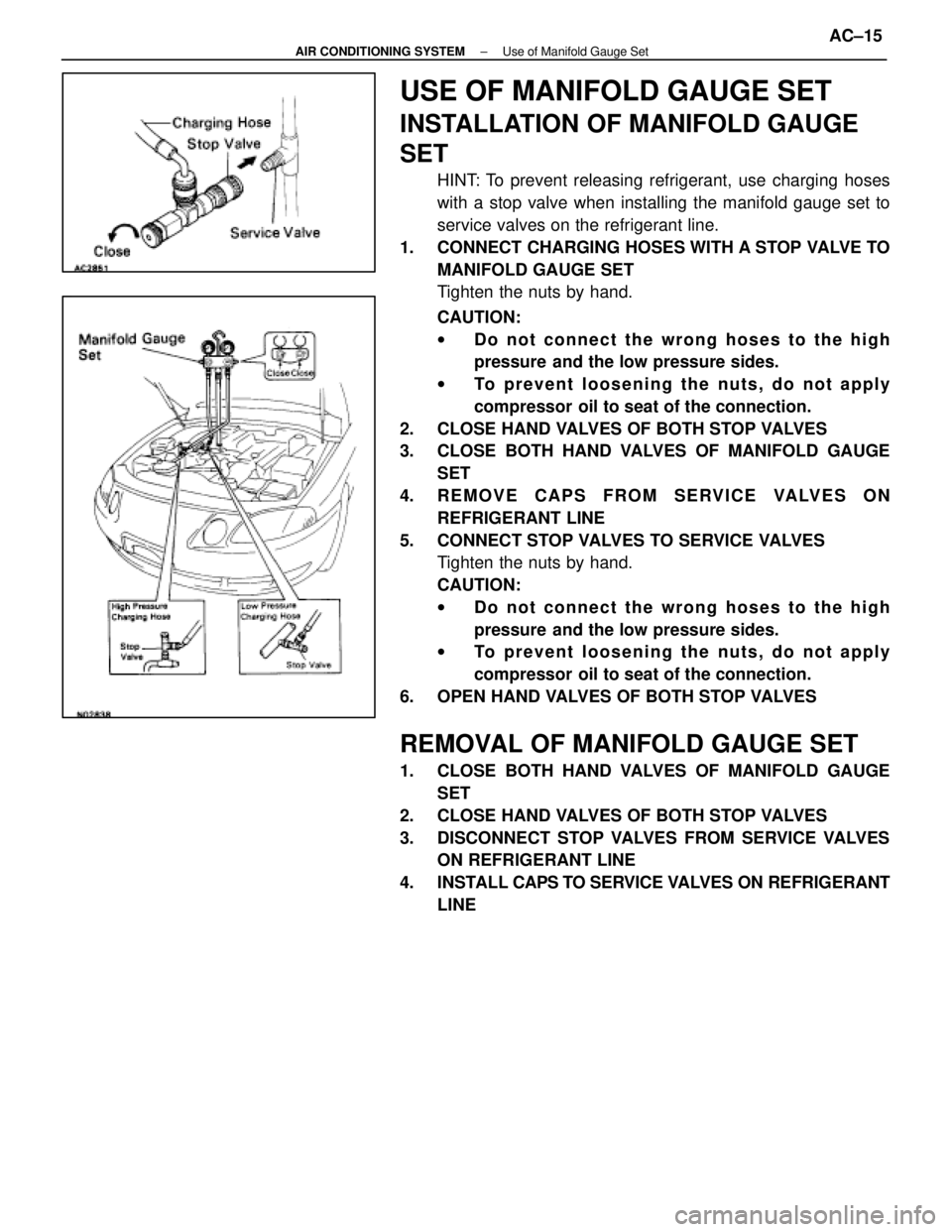
HINT: To prevent releasing refrigerant, use charging hoses
with a stop valve when installing the manifold gauge set to
service valves on the refrigerant line.
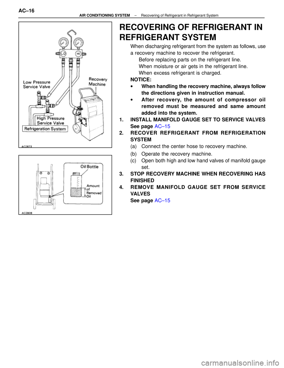
1. CONNECT CHARGING HOSES WITH A STOP VALVE TO MANIFOLD GAUGE SET
Tighten the nuts by hand.
CAUTION:
wDo not connect the wrong hoses to the high
pressure and the low pressure sides.
w To prevent loosening the nuts, do not apply
compressor oil to seat of the connection.
2. CLOSE HAND VALVES OF BOTH STOP VALVES
3. CLOSE BOTH HAND VALVES OF MANIFOLD GAUGE SET
4. REMOVE CAPS FROM SERVICE VALVES ON REFRIGERANT LINE
5. CONNECT STOP VALVES TO SERVICE VALVES Tighten the nuts by hand.
CAUTION:
wDo not connect the wrong hoses to the high
pressure and the low pressure sides.
w To prevent loosening the nuts, do not apply
compressor oil to seat of the connection.
6. OPEN HAND VALVES OF BOTH STOP VALVES
REMOVAL OF MANIFOLD GAUGE SET
1. CLOSE BOTH HAND VALVES OF MANIFOLD GAUGE SET
2. CLOSE HAND VALVES OF BOTH STOP VALVES
3. DISCONNECT STOP VALVES FROM SERVICE VALVES ON REFRIGERANT LINE
4. INSTALL CAPS TO SERVICE VAL VES ON REFRIGERANT
LINE
±
AIR CONDITIONING SYSTEM Use of Manifold Gauge SetAC±15
WhereEverybodyKnowsYourName
Page 57 of 4087

RECOVERING OF REFRIGERANT IN
REFRIGERANT SYSTEM
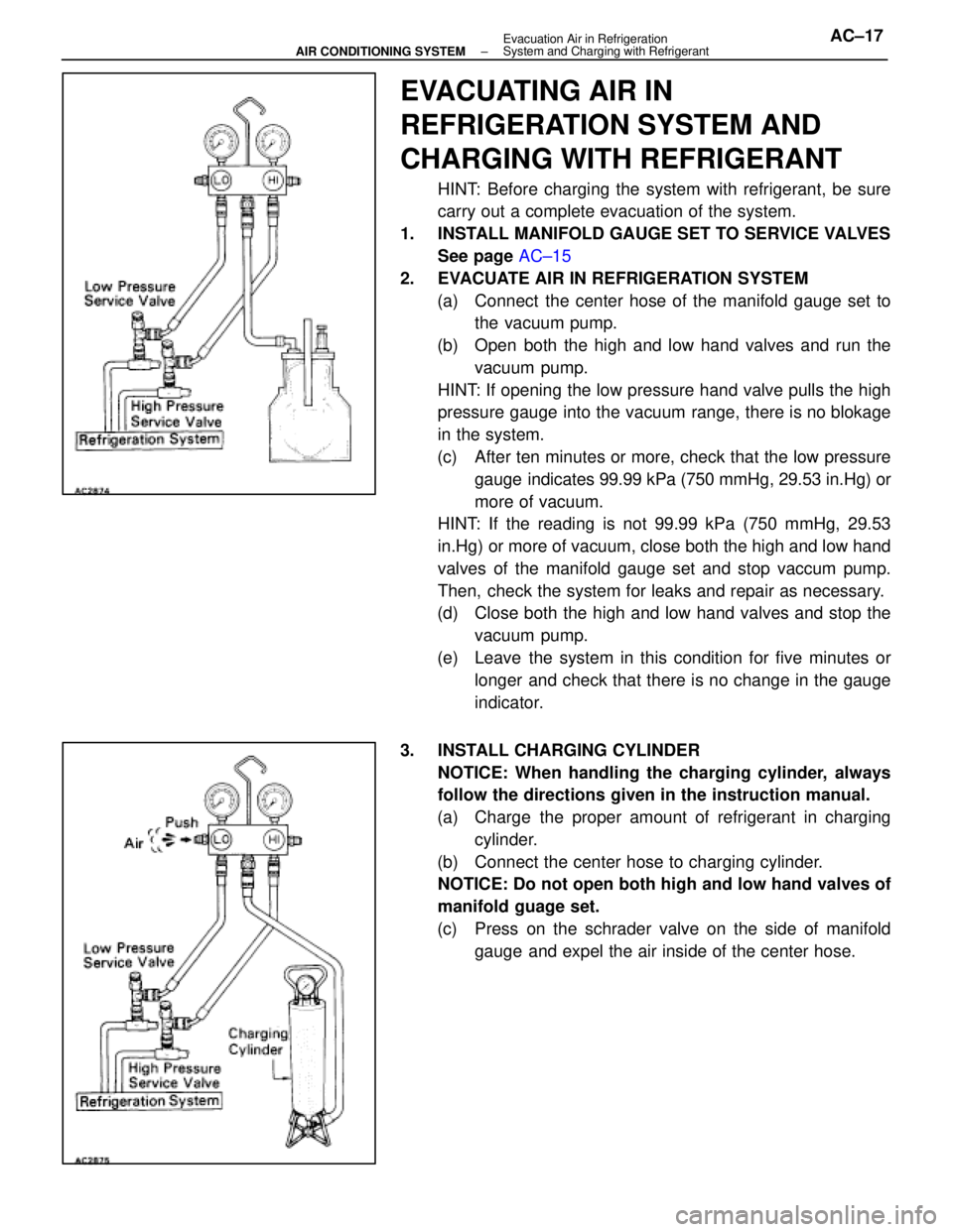
When discharging refrigerant from the system as follows, use
a recovery machine to recover the refrigerant.Before replacing parts on the refrigerant line.
When moisture or air gets in the refrigerant line.
When excess refrigerant is charged.
NOTICE:
w When handling the recovery machine, always follow
the directions given in instruction manual.
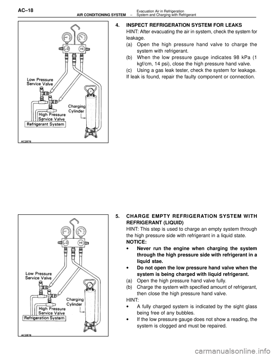
w After recovery, the amount of compr essor oil
removed must be measured and same am ount
added into the system.
1. INSTALL MANIFOLD GAUGE SET TO SERVICE VALVES See page AC±15
2. RECOVER REFRIGERANT FROM REFRIGERATION
SYSTEM
(a) Connect the center hose to recovery machine.
(b) Operate the recovery machine.
(c) Open both high and low hand valves of manifold gauge set.
3. STOP RECOVERY MACHINE WHEN RECOVERING HAS FINISHED
4. REMOVE MANIFOLD GAUGE SET FROM SERVICE VA LV E S
See page AC±15
AC±16
±
AIR CONDITIONING SYSTEM Recovering of Refrigerant in Refrigerant System
WhereEverybodyKnowsYourName
Page 58 of 4087

EVACUATING AIR IN
REFRIGERATION SYSTEM AND
CHARGING WITH REFRIGERANT
HINT: Before charging the system with refrigerant, be sure
carry out a complete evacuation of the system.
1. INSTALL MANIFOLD GAUGE SET TO SERVICE VALVES See page AC±15
2. EVACUATE AIR IN REFRIGERATION SYSTEM (a) Connect the center hose of the manifold gauge set to the vacuum pump.
(b) Open both the high and low hand valves and run the vacuum pump.
HINT: If opening the low pressure hand valve pulls the high
pressure gauge into the vacuum range, there is no blokage
in the system.
(c) After ten minutes or more, check that the low pressure gauge indicates 99.99 kPa (750 mmHg, 29.53 in.Hg) or
more of vacuum.
HINT: If the reading is not 99.99 kPa (750 mmHg, 29.53
in.Hg) or more of vacuum, close both the high and low hand
valves of the manifold gauge set and stop vaccum pump.
Then, check the system for leaks and repair as necessary.
(d) Close both the high and low hand valves and stop the
vacuum pump.
(e) Leave the system in this condition for five minutes or longer and check that there is no change in the gauge
indicator.
3. INSTALL CHARGING CYLINDER NOTICE: When handling the charging cylinder, always
follow the directions given in the instruction manual.
(a) Charge the proper amount of refrigerant in charging cylinder.
(b) Connect the center hose to charging cylinder. NOTICE: Do not open both high and low hand valves of
manifold guage set.
(c) Press on the schrader valve on the side of manifold gauge and expel the air inside of the center hose.
±
AIR CONDITIONING SYSTEM Evacuation Air in Refrigeration
System and Charging with RefrigerantAC±17
WhereEverybodyKnowsYourName
Page 59 of 4087

4. INSPECT REFRIGERATION SYSTEM FOR LEAKSHINT: After evacuating the air in system, check the system for
leakage.
(a) Open the high pressure hand valve to charge the system with refrigerant.
(b) When the low pressure g auge indicates 98 kPa (1
kgf/cm, 14 psi), close the high pressure hand valve.
(c) Using a gas leak tester, check the system for leakage. If leak is found, repair the faulty component or connection.
5. CHARGE EMPTY REFRIGERATION SYSTEM WITH REFRIGERANT (LIQUID)
HINT: This step is used to charge an empty system through
the high pressure side with refrigerant in a liquid state.
NOTICE:
wNever run the engine when charging the system
through the high pressure side with refrigerant in a
liquid stae.
w Do not open the low pressure hand valve when the
system is being charged with liquid refrigerant.
(a) Open the high pressure hand valve fully.
(b) Charge the system with specified amount of refrigerant, then close the high pressure hand valve.
HINT:
w A fully charged system is indicated by the sight glass
being free of any bubbles.
w If the low pressure gauge does not show a reading, the
system is clogged and must be repaired.
AC±18
±
AIR CONDITIONING SYSTEM Evacuation Air in Refrigeration
System and Charging with Refrigerant
WhereEverybodyKnowsYourName
Page 60 of 4087
6. CHARGE PARTIALLY REFRIGERATION SYSTEM WITHREFRIGERANT (VAPOR)
HINT: This step is used to charge the system through the low
pressure side with refrigerant in a vapor state.
NOTICE: Do not open the high pressure hand valve when
running the engine.
(a) Run the engine at ideling speed and operate the air
conditioner.
(b) Open the low pressure hand valve. NOTICE: Adjust the hand valve so that the low pressure
gauge does not indicate over limited pressure of charg-
ing cylinder.
(c) Close the low pressure hand valve when the sight glass is free of any bubbles and stop the engine.
NOTICE: Be careful not to overcharge the system with re-
frigerant as it may cause of troubles.
7. REMOVE MANIFOLD GAUGE SET FROM SERVICE VA LV E S
See page AC±15
±
AIR CONDITIONING SYSTEM Evacuation Air in Refrigeration
System and Charging with RefrigerantAC±19
WhereEverybodyKnowsYourName
Page 254 of 4087

Circuit Inspection
Diag. Code (Normal)Source Voltage Drop
CIRCUIT DESCRIPTION
The airbag system is equipped with a voltage±increase circuit (DC±DC\
converter) in the center airbag
sensor assembly in case the source voltage drops.
When the battery voltage drops, the voltage±increase circuit (DC±DC c\
onverter) functions to increase
the voltage of the airbag system to normal voltage.
The diagnosis system malfunction display for this circuit is different to other circuits±when the airbag
warning light remains lit up and the diagnostic code is a normal code, source voltage d\
rop is indicated.
Malfunction in this circuit is not recorded in the center airbag sensor assembly, and approx. 10 se-
conds after the source voltage returns to normal, the airbag warning lig\
ht automatically goes off.
Code No.
Diagnosis
(Normal)Source voltage drop.
DIAGNOSTIC CHART
Preparation.
Does airbag warning light turn on after
approx. 10 seconds?
Check battery and charging system
(See page CH±1). Check diagnostic code, and if a
malfunction code is output,
perform troubleshooting according
to malfunction code.
If a normal code is output,
replace center airbag sensor
assembly.
WIRING DIAGRAM
AB±40SRS AIRBAG
± Troubleshooting
WhereEverybodyKnowsYourName
Page 255 of 4087

(1) Turn ignition switch LOCK.
(2) Disconnect center airbag sensor assemblyconnector.
(3) Turn ignition switch ON. But do not start engine.
(4) Measure voltage at IG
2 or ACC on connector
wire harness side of center airbag assembly and
operate electric system (defogger, wiper,
headlight, heater, blower, etc.).
Voltage: 6 V ± 11.5 V at IG
2 and ACC.
(5) Turn electric system switch OFF.
(6) Turn ignition switch LOCK.
(7) Remove voltmeter and connect center airbag sensor assembly.
Does airbag warning light turn off after approx. 10 seconds?
Preparation.
Turn ignition switch ON.
Operate electric system checked in [ 1 ] (4) and
check that airbag warning light goes off after
approx. 10 seconds.
Check diagnostic code, and if a malfunction
code is output, perform troubleshooting
according to malfunction code. If a normal
code is output, replace center airbag
sensor assembly.
Check battery and charging system
(See page CH±1)
INSPECTION PROCEDURE
AB±41SRS AIRBAG ± Troubleshooting
WhereEverybodyKnowsYourName
Page 814 of 4087

Description
The power source supplies power to each of the vehicle's electrical devices. It is composed of the battery, fuses
and relays, which are located centrally at relay block No. 2 and relay block No. 6 i\
n the engine compartment
and junction block No. 1 relay block No. 4 and relay block No. 5 in the \
cabin near the driver's feet.
Related systems for each Fuse
No.Part NameRelated Systems or Parts
1IGN � Charging System � AIR±BAG System1IGN � Engine
2ST � Starter
3WIPER � Wiper and Washer System
4HTR � Defogger System � A/C System
5ENGINE � Charging System
6RADIO NO. 2 � Audio System � Power Mirror System
� Cigarette Lighter � A/C System
7CIG � Combination Meter System � AIR±BAG System7CIG � Shift Lock System � Theft Deterrent System
� TEL System
8STOP � Stop Light System � Cruise Control System
9TURN � Turn Signal and Hazard
Warning Light System � Cornnering Light System
10MIR HTR � Mirror Heater System
11PANEL � Illumination Light System
12ECU±B � Combination Meter System � AIR±BAG System
� Combination Meter System � ECT System
13GAUGE � Back±Up Light � Transmission Indicator
� Light Failare Sensor � ABS and TRAC
� Power Seat System � Door Lock Control System
� TEL System � Shift Lock System
14ECU±IG � Radiator Fan � Auto Antenna
� Electric Tension Reducer System � Power Steering
� Auto±Tilt away Steering � Cruise Control System
15TAIL � Taillight System � Side Marker15TAIL � Clearance Light
16DOOR � Power Seat System � Luggage Door Opener16DOOR � Door Lock Control System � Fuel Lid Opener System
17IG SWUpstream of ECU±IG, ENGINE, WIP, HTR, TURN, GAUGE, and ST Fuse
18PWR � Power Window System � Sliding Roof System
19ABS NO. 1 � ABS and TRAC
20AM1Upstream of MIR HTR, TAIL, PANEL, STOP, ECUA±B, DOOR and PWR Fuse
21ALTUpstream of DEF, HTR, AM1, and ABS No. 1 Fuse
BE±18±
BODY ELECTRICAL SYSTEM Power Source
WhereEverybodyKnowsYourName