Page 3437 of 4087

CIRCUIT DESCRIPTION
The distributor in the Engine Control System contains three pick±up coil\
s (G1, G2 and NE).
The G1, G2 signals inform")
CIRCUIT INSPECTIONDiag. Code 12
RPM Signal Circuit (No. 1)
CIRCUIT DESCRIPTION
The distributor in the Engine Control System contains three pick±up coil\
s (G1, G2 and NE).
The G1, G2 signals inform the ECU of the standard crankshaft angle.
The NE signals inform the ECU of the crankshaft angle and the engine spe\
ed.
����� �����Code No.����������������� �����������������Diagnostic Code Detecting Condition�������������� ��������������Trouble Area
����� ���������������������� �����������������
NoºNEºorºG1ºandºG2ºsignal to ECU within 2
�������������� ��������������
�Open or short in NE G circuit����� ���������������������� �����������������No ºNEº or ºG1º and ºG2º signal to ECU within 2
sec after cranking�������������� ��������������� Open or short in NE, G circuit.
� Distributor
����� �����12����������������� �����������������sec. after cranking.�������������� ��������������� Distributor
� Open or short in STA circuit.
ECU����� ���������������������� �����������������Open in ºGº � circuit.�������������� ��������������
Oen or short in STA circuit.
� ECU
TR±46±
ENGINE TROUBLESHOOTING Circuit Inspection
WhereEverybodyKnowsYourName
Page 3438 of 4087
DIAGNOSTIC CHART
WIRING DIAGRAM
Check resistance of each pickup coils in
distributor
Check for open and short in harness and
connector between ECU and distributor.
Check air gap.
Check and replace ECU.
Replace distributor.
Repair or rep lace harness or connector.
Replace distributor
±
ENGINE TROUBLESHOOTING Circuit InspectionTR±47
WhereEverybodyKnowsYourName
Page 3439 of 4087
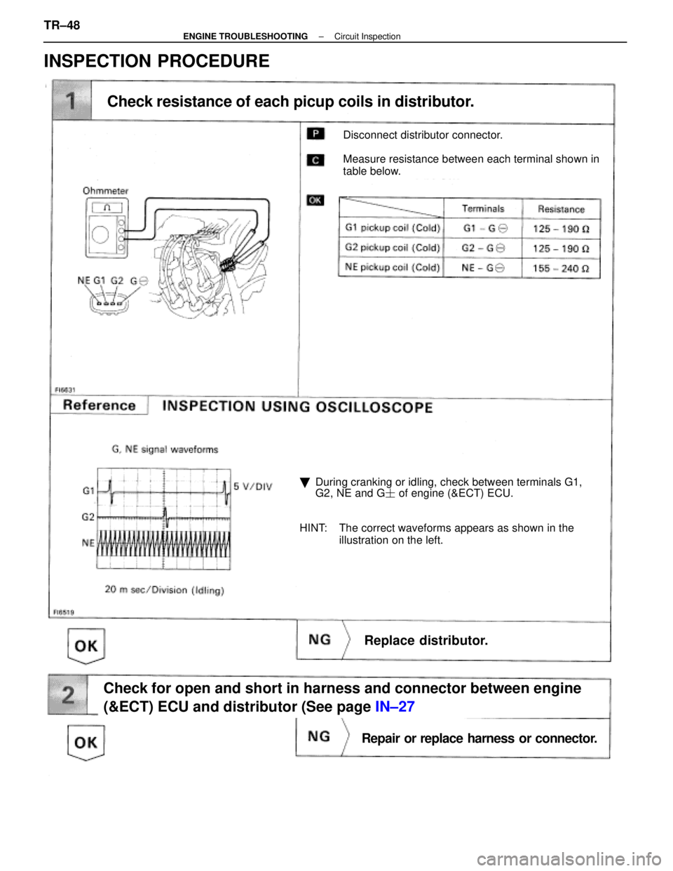
Disconnect distributor connector.
Measure resistance between each terminal shown in
table below.
Check resistance of each picup coils in distributor.
�During cranking or idling, check between terminals G1,
G2, NE and G � of engine (&ECT) ECU.
HINT: The correct waveforms appears as shown in the illustration on the left.
Replace distributor.
Check for open and short in harness and connector between engine
(&ECT) ECU and distributor (See page IN±27
Repair or replace harness or connector.
INSPECTION PROCEDURE
TR±48±
ENGINE TROUBLESHOOTING Circuit Inspection
WhereEverybodyKnowsYourName
Page 3440 of 4087
Remove distributor cap & rotor.
Using SST (G1 and G2 pickups) and a thikness gauge
(NE pickup). measure the air gap between the signal
rotor projection and pickup coil.
SST 09240±00020 fro G1 and G2 pickups
Air gap: 0.2±0.4 mm (0.008±0.016 in.)
Replace distributor.
Check and replace engine (& ECT) ECU.
±
ENGINE TROUBLESHOOTING Circuit InspectionTR±49
WhereEverybodyKnowsYourName
Page 3441 of 4087

CIRCUIT DESCRIPTION
Cam position sensors (G1 and G2 signals) and engine speed sensor (NE sig\
nal) consist of a signal plate
and a pick up c")
CIRCUIT INSPECTIONDiag. Code 12
RPM Signal Circuit (No.1)
CIRCUIT DESCRIPTION
Cam position sensors (G1 and G2 signals) and engine speed sensor (NE sig\
nal) consist of a signal plate
and a pick up coil.
The G1, G2 signal plates have one tooth each on its outer circumference and\
are mounted on the left and
right bank camshafts.
When the camshafts rotate, the protrusion on the signal plate and the air gap on the pick up coil change,
causing fluctuations in the magnetic field and generating an electromotive forc\
e in the pick up coil.
The NE signal plate has 12 teeth and is mounted on the crankshaft. The NE s\
ignal sensor generates 12
NE signals per engine revolution. The ECU detects the standard crankshaf\
t angle based on the G1, G2
signals, and the actual crankshaft angle and the engine speed by the NE \
signals.
Code No.Diagnostic Code Detecting ConditionTrouble Area
wOpen or short in engine speed sensor, No. 1,w Oen or short in engine s eed sensor, No. 1,
No. 2 cam position sensor circuit
12No ºNEº or ºG1º and ºG2º signal to ECU
No. 2 cam osition sensor circuit
w Engine speed sensor12No NE or G1 and G2 signal to ECU
within 2 sec. after cranking.
wEngine s eed sensor
wNo. 1, No. 2 cam position sensorgNo. 1, No. 2 cam osition sensor
wStarter
wECU
TR±48±
ENGINE TROUBLESHOOTING Circuit Inspection
WhereEverybodyKnowsYourName
Page 3442 of 4087
DIAGNOSTIC CHART
WIRING DIAGRAM
±
ENGINE TROUBLESHOOTING Circuit InspectionTR±49
WhereEverybodyKnowsYourName
Page 3443 of 4087
OKNG
INSPECTION PROCEDURE
1Check engine speed sensor, No. 1, No. 2 cam position sensor
C
OK
PFor engine speed sensor.
(2) Remove engine under cover.
(2) Disconnected engine speed sensor connector.
For No.1, No. 2 cam position sensor,
(2) Disconnect No. 1, No. 2 cam poisition sensor con-nectors.
Measure resistance of engine speed sencor, No. 1 and
No. 2 cam position sensor.
Replace engine speed sensor, No. 1, No. 2 cam poistion
sensor.
TR±50
±
ENGINE TROUBLESHOOTING Circuit Inspection
WhereEverybodyKnowsYourName
Page 3444 of 4087
OKNG
OKNG
2Check for open and short in harness and connector between engine & ECT ECU an\
d each sen-
sor (See page IN±27).
Repair or replace harness or connector.
3Inspect sensor installation and teeth of signal plate.
Tighen the sensor.
Replace signal plate.
Check and replace engine and ECT ECU.
±
ENGINE TROUBLESHOOTING Circuit InspectionTR±51
WhereEverybodyKnowsYourName

 and a thikness gauge
(NE pickup). measure the air gap between the signal
rotor projection and pickup coil.
SST 09240±00020 fro G1 and G2")

 Remove engine under cover.
(2) Disconnected engine speed sensor connector.
Fo")
.
Repair or replace harness or connector.
3Inspect sensor installation and t")