Page 3464 of 4087
OKNG
OKNG
INSPECTION PROCEDURE
1Disconnect the engine & ECT ECU connector, check voltage between terminals HTL1, HTR1 of
engine & ECT ECU connector and body ground.
C
OK
P(2) Connect the Check Harness A.(See page TR±30)
(2) Disconnect engine & ECT ECU connector.
(2) Turn ignition switch on.
Measure voltage beween terminals HTL1, HTR1 of en-
gine & ECT ECU connector and body ground.
Voltage: 10 ± 14 V
Go to step [3].
2Check main oxygen sensor heater.
C
OK
PDisconnect main oxygen sensor connector.
Measure resistance between terminals 1 and 2 of main
oxygen sensor connector.
Resistance: 5.1 ± 6.3 � at 20 �C (68 �F)
Replace main oxygen sensor.
Check and repair harness or connector between
main relay and main oxygen sensor, main oxygen
sensor and engine & ECT ECU.
TR±65±
ENGINE TROUBLESHOOTING Circuit Inspection
WhereEverybodyKnowsYourName
Page 3465 of 4087

OKNG
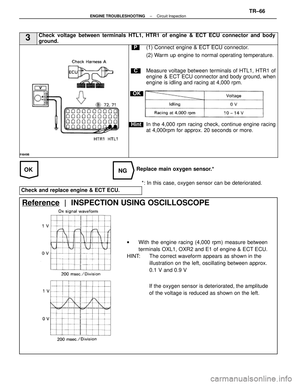
3Check voltage between terminals HTL1, HTR1 of engine & ECT ECU connector and \
body
ground.
C
OK
Hint
P(1) Connect engine & ECT ECU connector.
(2) Warm up engine to normal operating temperature.
Measure voltage between terminals of HTL1, HTR1 of
engine & ECT ECU connector and body ground, when
engine is idling and racing at 4,000 rpm.
In the 4,000 rpm racing check, continue engine racing
at 4,000rpm for approx. 20 seconds or more.
Replace main oxygen sensor.**: In this case, oxygen sensor can be deteriorated.
Check and replace engine & ECT ECU.
Reference | INSPECTION USING OSCILLOSCOPE
w With the engine racing (4,000 rpm) measure between
terminals OXL1, OXR2 and E1 of engine & ECT ECU.
HINT: The correct waveform appears as shown in the
illustration on the left, oscillating between approx.
0.1 V and 0.9 V
If the oxygen sensor is deteriorated, the amplitude
of the voltage is reduced as shown on the left.
±
ENGINE TROUBLESHOOTING Circuit InspectionTR±66
WhereEverybodyKnowsYourName
Page 3474 of 4087

Diag Code 25 26
Air±Fuel Ratio Lean Malfunction
Diag. Code 25, 26
Air±Fuel Ratio Rich Malfunction
CIRCUIT DESCRIPTION
Refer to page TR±62 for the circuit description.
Code No.
Diagnostic Code Detecting SystemTrouble Area
(1) Main oxygen sensor voltage is 0.45 V or less (lean) for 90 sec. under conditions
(a) and (b).
(2 trip detection logic)
*2
(a) Coolant temp.: 70 °C (158 °F)
or more.
(b) Engine speed: 1,500 rpm or more.
� Open or short in main oxygen sensor
circuit
� Main oxygen sensor
� Ignition system
� ECU
25
(2)*1 Difference of air±fuel ratio feedback
compensation value between front (No.
1 3 cylinders) and rear (No. 4 6
cylinders) is more than 15 percentage
for 20 sec. or more under conditions (a)
and (b).
(2 trip detection logic)
*2
(a) Engine speed: 2,000 rpm or more.
(b) Coolant temp.: Between 60 °C
(140 °F) and 95 °C (203 °F).
� Open and short in injector circuit.
� Fuel line pressure (injector leak, blockage)
� Mechanical system malfunction (skipping
teeth of timing belt)
� Ignition system
� Compression pressure (foreign object
caught in valve)
� Air flow meter (air intake)
� ECU
(3)*1 Engine speed varies by more than 15
rpm over the preceding crank angle period
during a period of 20 sec. or more under
conditions (a) and (b).
(2 trip detection logic)
*2
(a) Engine speed: Idling
(b) Coolant temp.: Between 60 °C
(140 °F) and 95 °C (203 °F).
� Open and short in injector circuit.
� Fuel line pressure (injector leak, blockage)
� Mechanical system malfunction (skipping
teeth of timing belt)
� Ignition system
� Compression pressure (foreign object
caught in valve)
� Air flow meter (air intake)
� ECU
26*1
(1) Difference of air±fuel ratio feedback
compensation value between front (No. 1
3 cylinders) and rear (No.4 6 cylinders) is
more than 15 percentage for 20 sec. or
more under conditions (a) and (b).
(2 trip detection logic)
*2
(a) Engine speed: 2,000 rpm or more.
(b) Coolant temp.: Between 60 °C
(140 °F) and 95 °C (203 °F).
� Open and short in injector circuit.
� Fuel line pressure (injector leak, blockage)
� Mechanical system malfunction (skipping
teeth of timing belt)
� Ignition system
� Compression pressure (foreign object
caught in valve)
� Air flow meter (air intake)
� ECU
261
(2) Engine speed varies by more than 15
rpm over the preceding crank angle peri-
od during a period of 20 sec. or more un-
der conditions (a) and (b).
(2 trip detection logic)
*2
(a) Engine speed: Idling
(b) Coolant temp.: Between 60 °C
(140 °F) and 95 °C (203 °F).
� Open and short in injector circuit.
� Fuel line pressure (injector leak, blockage)
� Mechanical system malfunction (skipping
teeth of timing belt)
� Ignition system
� Compression pressure (foreign object
caught in valve
� Air flow meter (air intake)
� ECU
*1: Only for USA specification vehicles.
*2: See page TR±25.
TR±70
±
ENGINE TROUBLESHOOTING Circuit Inspection
WhereEverybodyKnowsYourName
Page 3476 of 4087
DIAGNOSTIC CHART
Check voltage of terminal VF.
Repair or replace harness or
connector.
Repair or replace.
Repair or replace.
Replace main oxygen sensor.
Repair or replace.
Repair or replace.
Replace main oxygen sensor.
Check voltage of terminal OX.
Check for open and short in harness and
connector.
Check each item found to be a possible
cause of problem.
Check compression.
Does malfunction disappear when a good
main oxygen sensor is installed?
Check and replace ECU.
Check each item found to be a possible
cause of problem.
Check compression.
Does malfunction disappear when a good
main oxygen sensor is instaled?
Check and replace ECU.
NG Type II
NG Type I
WIRING DIAGRAM
Refer to page TR±62 for the WIRING DIAGRAM.
TR±72
±
ENGINE TROUBLESHOOTING Circuit Inspection
WhereEverybodyKnowsYourName
Page 3477 of 4087
NG
Type I
NG
Type II
NGOK
INSPECTION PROCEDURE
1Check voltage between terminals VF1, VF2 and E1 of check connector.
C
P
Cau-tion
1. Warm up engine at normal operating temperature
2. Connect terminals TE1 and E1 of check connector.
3. Connect positive prove to terminal VF1, VF2 and
negative prove to terminal E1 of check connector.
1. Warm up the oxygen sensor by running engine at 2,500 rpm for about 2 minutes.
2. Then, maintaining engine at 2,500 rpm, count how many times needle of voltmeter fluctuates between
0 and 5 V.
Go to step �.
2Check voltage between terminals OX1, OX2 and E1 of check connector.
C
OK
Hint
PWarm up engine at normal operating temperature.
Measure voltage between terminals OX1, OX2 and E1
of check connector when engine is suddenly raced to
full throttle.
The voltage should be 0.5 V or higher at least once.
Perform inspection within 1 second.
Go to step �.
±
ENGINE TROUBLESHOOTING Circuit InspectionTR±73
WhereEverybodyKnowsYourName
Page 3478 of 4087

OKNG
OKNG
OKNG
NGYES
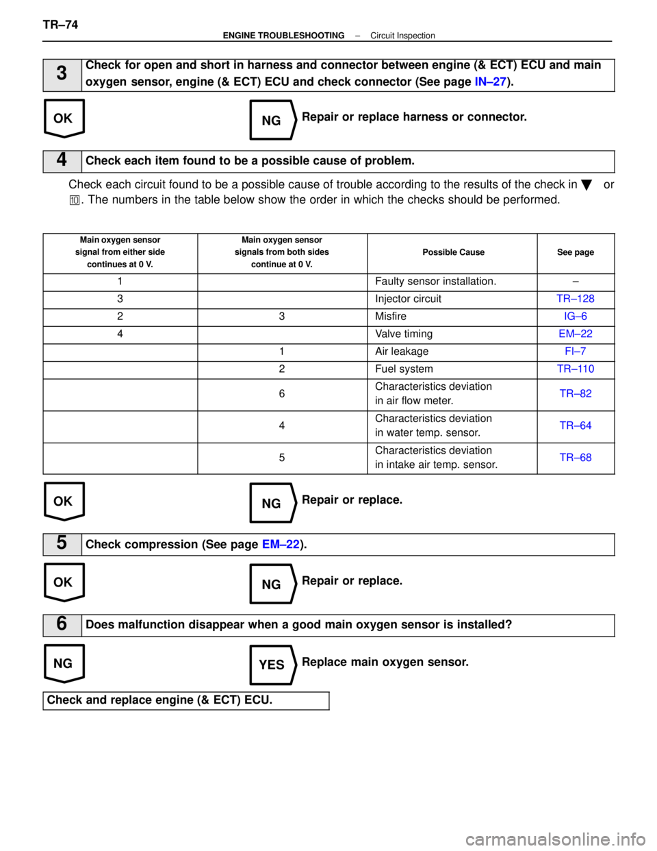
3Check for open and short in harness and connector between engine (& ECT) EC\
U and main
oxygen sensor, engine (& ECT) ECU and check connector (See page IN±27).
Repair or replace harness or connector.
4Check each item found to be a possible cause of problem.
Check each circuit found to be a possible cause of trouble according to the r\
esults of the check in ��or
� . The numbers in the table below show the order in which the checks shoul\
d be performed.
Main oxygen sensor
signal from either side
continues at 0 V.Main oxygen sensor
signals from both sides
continue at 0 V.
Possible CauseSee page
1Faulty sensor installation.±
3Injector circuitTR±128
23MisfireIG±6
4Valve timingEM±22
1Air leakageFI±7
2Fuel systemTR±110
6Characteristics deviation
in air flow meter.TR±82
4Characteristics deviation
in water temp. sensor.TR±64
5Characteristics deviation
in intake air temp. sensor.TR±68
Repair or replace.
5Check compression (See page EM±22).
Repair or replace.
6Does malfunction disappear when a good main oxygen sensor is installed?
Replace main oxygen sensor.
Check and replace engine (& ECT) ECU.
TR±74±
ENGINE TROUBLESHOOTING Circuit Inspection
WhereEverybodyKnowsYourName
Page 3479 of 4087

OKNG
OKNG
NGYES
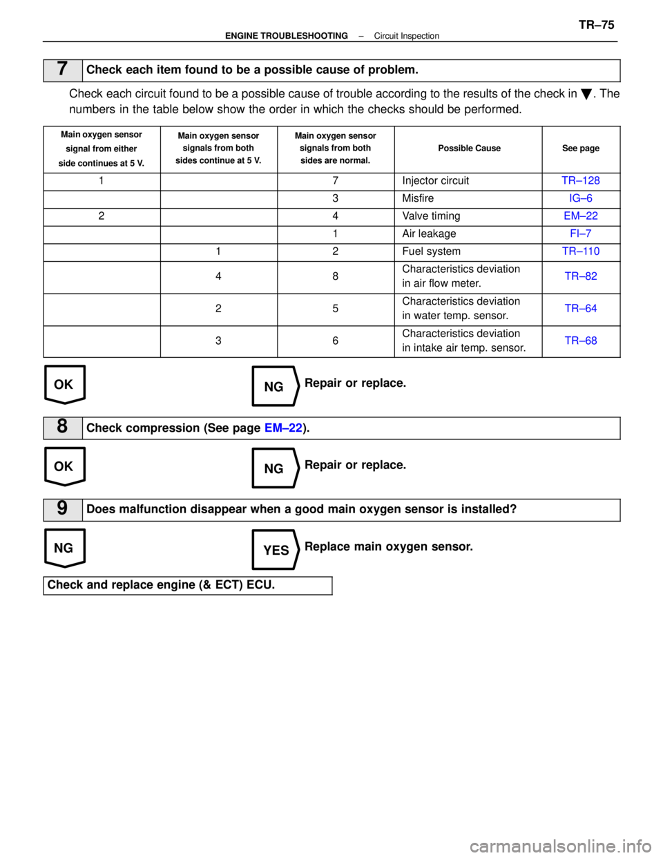
7Check each item found to be a possible cause of problem.
Check each circuit found to be a possible cause of trouble according to the r\
esults of the check in �. The
numbers in the table below show the order in which the checks should be perform\
ed.
Main oxygen sensor
signal from either
side continues at 5 V.Main oxygen sensor signals from both
sides continue at 5 V.Main oxygen sensor signals from both
sides are normal.
Possible CauseSee page
17Injector circuitTR±128
3MisfireIG±6
24Valve timingEM±22
1Air leakageFI±7
12Fuel systemTR±110
48Characteristics deviation
in air flow meter.TR±82
25Characteristics deviation
in water temp. sensor.TR±64
36Characteristics deviation
in intake air temp. sensor.TR±68
Repair or replace.
8Check compression (See page EM±22).
Repair or replace.
9Does malfunction disappear when a good main oxygen sensor is installed?
Replace main oxygen sensor.
Check and replace engine (& ECT) ECU.
±
ENGINE TROUBLESHOOTING Circuit InspectionTR±75
WhereEverybodyKnowsYourName
Page 3482 of 4087

Diag Code
25Air±Fuel Ratio Lean Malfunction
Diag. Code
26Air±Fuel Ratio Rich Malfunction
CIRCUIT DESCRIPTION
Refer to page TR±62 for the circuit description.
Code No.Diagnostic Code Detecting ConditionTrouble Area
(1) Main oxygen sensor voltage is 0.45 V or less (lean)
for 90 sec. under conditions (a) and (b).
(2 trip detection logic)*
(a) Coolant temp.: 60 5C (140 5F) or more.
(b) Engine speed: 1,500 rpm or more.�Open or short in main oxygen sensor circuit
�Main oxygen sensor
�Ignition system
�Water temp. sensor
25 V
26
(2) Main oxygen sensor voltage is alternating above and below 0.45 V at 5 times par
second or more under conditions (a) and (b).
(2 trip detection logic)*
(a) Engine speed: Idling
(b) Coolant temp.: Between 60 5C (140 5F)
and 95 5C (203 5F)
�Open or short in injector circuit.
�Fuel line pressure (injector blockage)
�Air flow meter (air intake)
�Engine ground bolt loose
�Foreign object caught in valve
(3) Difference of air±fuel ratio feedback compensation
value between right and left banks is more than 10
percentage for 30 sec. or more under conditions (a)
and (b).
(2 trip detection logic)*
(a) Engine speed : 2,000 rpm or more.
(b) Coolant temp.: Between 60 5C (140 5F)
and 95 5C (203 5F)
�Fuel line pressure (injector leak, blockage)
�Mechanical system malfunction
(skipping teeth of timing belt)
�Ignition system
*: See page TR±21.
±
ENGINE TROUBLESHOOTING Circuit InspectionTR±74
WhereEverybodyKnowsYourName