Page 1247 of 4087

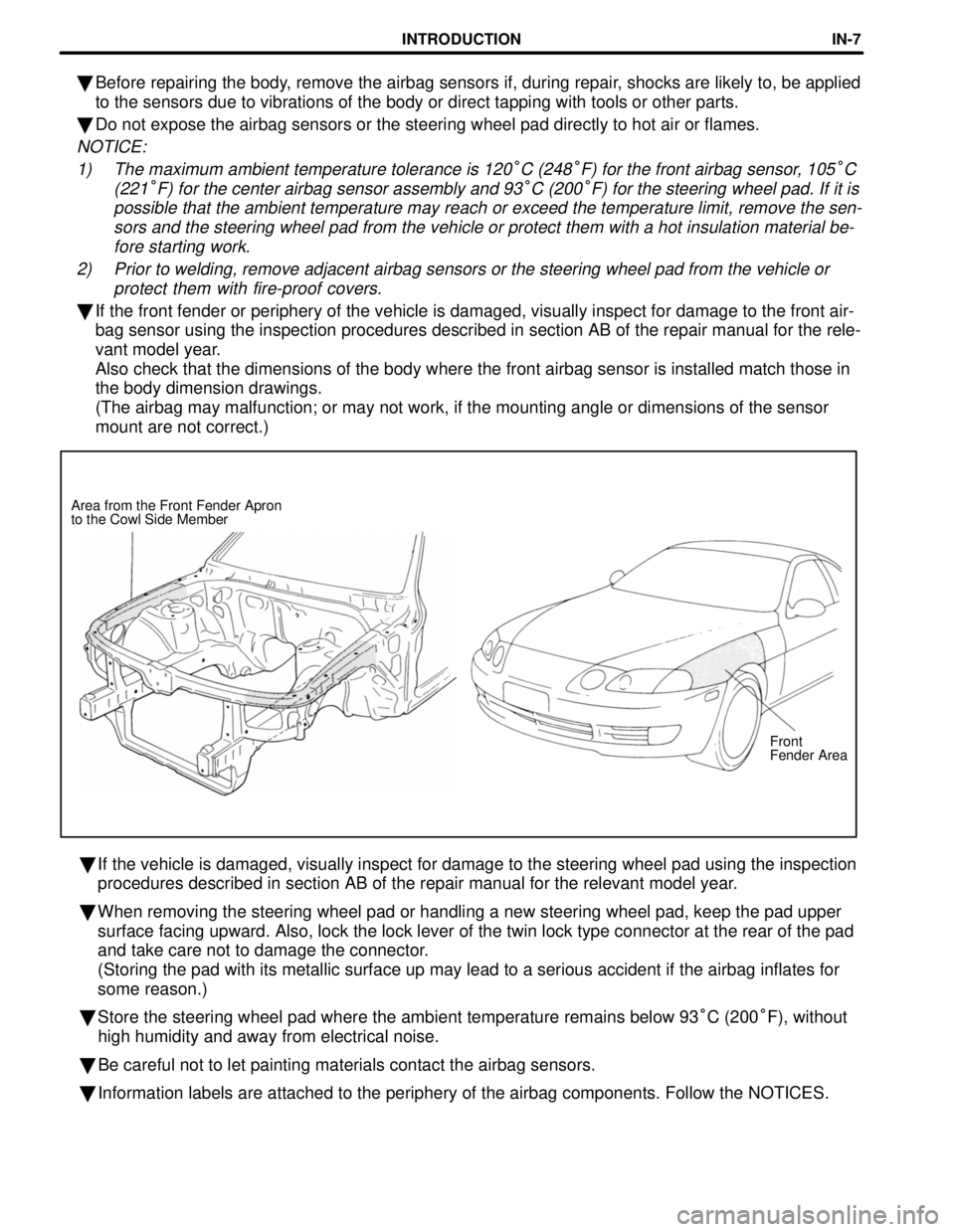
Front
Fender Area
Area from the Front Fender Apron
to the Cowl Side Member
�
Before repairing the body, remove the airbag sensors if, during repair, shocks are likely to, be applied
to the sensors due to vibrations of the body or direct tapping with tool\
s or other parts.
� Do not expose the airbag sensors or the steering wheel pad directly to h\
ot air or flames.
NOTICE:
1) The maximum ambient temperature tolerance is 120
°C (248°F) for the front airbag sensor, 105°C
(221
°F) for the center airbag sensor assembly and 93°C (200°F) for the steering wheel pad. If it is
possible that the ambient temperature may reach or exceed the temperatur\
e limit, remove the sen- sors and the steering wheel pad from the vehicle or protect them with a \
hot insulation material be-fore starting work.
2) Prior to welding, remove adjacent airbag sensors or the steering wheel p\
ad from the vehicle or protect them with fire-proof covers.
�If the front fender or periphery of the vehicle is damaged, visually ins\
pect for damage to the front air-
bag sensor using the inspection procedures described in section AB of th\
e repair manual for the rele-
vant model year.
Also check that the dimensions of the body where the front airbag sensor\
is installed match those in
the body dimension drawings.
(The airbag may malfunction; or may not work, if the mounting angle or \
dimensions of the sensor
mount are not correct.)
� If the vehicle is damaged, visually inspect for damage to the steering w\
heel pad using the inspection
procedures described in section AB of the repair manual for the relevant\
model year.
� When removing the steering wheel pad or handling a new steering wheel pa\
d, keep the pad upper
surface facing upward. Also, lock the lock lever of the twin lock type c\
onnector at the rear of the pad
and take care not to damage the connector.
(Storing the pad with its metallic surface up may lead to a serious acc\
ident if the airbag inflates for
some reason.)
� Store the steering wheel pad where the ambient temperature remains below\
93 °C (200 °F), without
high humidity and away from electrical noise.
� Be careful not to let painting materials contact the airbag sensors.
� Information labels are attached to the periphery of the airbag component\
s. Follow the NOTICES.
INTRODUCTIONIN-7
WhereEverybodyKnowsYourName
Page 1248 of 4087

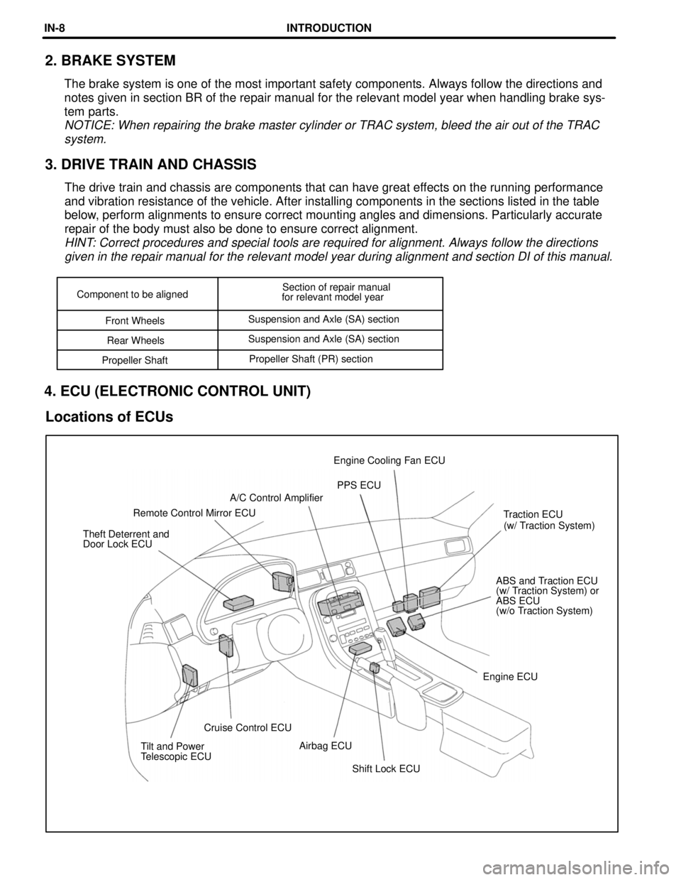
Shift Lock ECU
Tilt and Power
Telescopic ECU
Airbag ECU
Cruise Control ECU Engine ECUABS and Traction ECU
(w/ Traction System) or
ABS ECU
(w/o Traction System)
Theft Deterrent and
Door Lock ECU
(w/ Traction System)
Traction ECU
Remote Control Mirror ECU A/C Control Amplifier
PPS ECU
Engine Cooling Fan ECU
Component to be aligned
Section of repair manual
for relevant model year
Front Wheels Suspension and Axle (SA) section
Rear Wheels Suspension and Axle (SA) section
Propeller Shaft Propeller Shaft (PR) section
2. BRAKE SYSTEM
The brake system is one of the most important safety components. Always \
follow the directions and
notes given in section BR of the repair manual for the relevant model ye\
ar when handling brake sys-
tem parts.
NOTICE: When repairing the brake master cylinder or TRAC system, bleed t\
he air out of the TRAC
system.
3. DRIVE TRAIN AND CHASSIS
The drive train and chassis are components that can have great effects on the running performance
and vibration resistance of the vehicle. After installing components in \
the sections listed in the table
below, perform alignments to ensure correct mounting angles and dimensions. P\
articularly accurate
repair of the body must also be done to ensure correct alignment.
HINT: Correct procedures and special tools are required for alignment. Alway\
s follow the directionsgiven in the repair manual for the relevant model year during alignment \
and section DI of this manual.
4. ECU (ELECTRONIC CONTROL UNIT)
Locations of ECUs
INTRODUCTIONIN-8
WhereEverybodyKnowsYourName
Page 2165 of 4087

18. INSPECT SRS AIRBAGDriver Airbag:
Visually inspect the steering wheel pad (airbag and inflater).
wUse the diagnosis check to check if there are
abnormalities.
w Check that there are no cuts, cracks or noticeable color
changes on the surface of the steering wheel pad or in
the center groove of the pad.
w Remove the steering wheel pad from the vehicle and
check the wiring and steering wheel for damage and
corrosion due to rusting, etc.
If necessary, replace the steering wheel pad.
Front Passenger Airbag:
Visually inspect the front passenger airbag assembly (airbag
and inflater).
w Use the diagnosis check to check if there are
abnormalities.
w Check that there are no cuts, cracks or noticeable color
changes in the front passenger airbag door.
w Remove the front passenger airbag assembly from the
vehicle and check the wiring and front passenger airbag
door for damage and corrosion due to rusting, etc.
If necessary, replace the front passenger airbag assembly.
CAUTION:
w For removal and replacement of the steering wheel pad
or front passenger airbag assembly, see page RS±28 and
be sure to perform the operation in the correct order.
w Before disposing of the steering wheel pad or front
passenger airbag assembly must first be deployed by
using SST and wiring harness connector (See page
RS±28 ).
19. INSPECT STEERING GEAR HOUSING OIL
Check the steering gear housing for oil leakage.
MA±14
±
MAINTENANCE (1UZ ± FE)
WhereEverybodyKnowsYourName
Page 3023 of 4087
GENERAL DESCRIPTION
SR0E7±02
�Care must be taken to replace parts properly because they could affect the p\
erformance of the steering
system and result in a driving hazard.
� The steering wheel pad has an airbag built in, so take all due precautio\
ns when handling it. For more
details, see the RS section.
TROUBLESHOOTING
SR0E8±02
You will find the cause of trouble more easily by properly using the table \
shown below. In this table, the
numbers indicate the priority of the probable cause of trouble. Check each part in the order shown. If neces-
sary, repair or replace the part.
SA±3
SR±113SA±41
SR±167
SR±163
SA±16SA±3
SR±2±
STEERING GENERAL DESCRIPTION, TROUBLESHOOTING
WhereEverybodyKnowsYourName
Page 3024 of 4087
GENERAL DESCRIPTION
SR0E7±02
�Care must be taken to replace parts properly because they could affect the p\
erformance of the steering
system and result in a driving hazard.
� The steering wheel pad has an airbag built in, so take all due precautio\
ns when handling it. For more
details, see the RS section.
TROUBLESHOOTING
SR0E8±02
You will find the cause of trouble more easily by properly using the table \
shown below. In this table, the
numbers indicate the priority of the probable cause of trouble. Check each part in the order shown. If neces-
sary, repair or replace the part.
SA±3
SR±113SA±41
SR±167
SR±163
SA±16SA±3
SR±2±
STEERING GENERAL DESCRIPTION, TROUBLESHOOTING
WhereEverybodyKnowsYourName
Page 3032 of 4087

MAIN POINTS OF REMOVAL AND
INSTALLATION
NOTICE:
wIf the SRS (Supplemental Restraint System) connector is
disconnected with the ignition switch at ON or ACC,
diagnostic trouble codes will be recorded.
w Never use SRS parts from another vehicle. When
replacing parts, replace with new parts.
1. DISCONNECT NEGATIVE (±) TERMINAL CABLE FROM
BATTERY
CAUTION: W ork must be started after 90 seconds from the time
the ignition switch is turned to the ªLOCKº position and the
negative (±) terminal cable is disconnected from the battery.
(See RS section)
2. REMOVE STEERING WHEEL PAD
(a) Place the front wheels facing straight ahead.
(b) Remove the No.2 and No.3 covers.
(c) Using a torx wrench, loosen the 4 torx screws. Torx wrench: T30 (Part No. 09042±00010 or locally manufac-
tured tool)
HINT: Loosen the 4 screws until the groove along the screw
circumference catches on the screw case.
(d) P u l l t h e w heel pad out from the steering wheel and
disconnect the Airbag connector.
NOTICE: When removing the wheel pad, take care not to pull
the Airbag wire harness.
CAUTION:
w When storing the wheel pad, keep the upper surface of
the pad facing upward.
w Never disassemble the wheel pad.
3. REMOVE STEERING WHEEL
(a) Disconnect the connector.
(b) Remove the steering wheel set nut.
(c) Place matchmarks on the steering wheel and main shaft.
(d) Using SST, remove the wheel.
SC400:
SST 09213±31021
SC300:
SST 09609±20011
SR±10
±
STEERING STEERING COLUMN
WhereEverybodyKnowsYourName
Page 3033 of 4087

4. CENTER SPIRAL CABLE
(a) Check that the front wheels are facing straight ahead.
(b) Turn the spiral cable counterclockwise by hand until it
becomes harder to turn the cable.
(c) Then rotate the spiral cable clockwise about 3 turns to align the red mark.
HINT: The spiral cable will rotate about 3 turns to either left
or right of the center.
5. INSTALL STEERING WHEEL
(a) Align matchmarks on the steering wheel and main shaft, and install the wheel to the shaft.
(b) Tighten the wheel set nut.
Torque: 35 N Vm (360 kgf Vcm, 26 ft Vlbf)
(c) Connect the connector.
6. INSTALL STEERING WHEEL PAD
(a) Connect the Airbag connector.
(b) Install the pad after confirming that the circumference groove
of the torx screws is caught on the screw case.
(c) Using a torx wrench, tighten the 4 torx screws.
Torque: 7.4 N Vm (75 kgf Vcm, 65 in. Vlbf)
NOTICE:
w Make sure the wheel pad is installed to the specified
torque.
w If the wheel pad has been dropped, or there are cracks,
dents or other defects in the case or connector, replace
the wheel pad with a new one.
w When installing the wheel pad, take care that the wiring
does not interfere with other parts and is not pinched
between other parts.
7. CHECK STEERING WHEEL CENTER POINT
8. CONNECT NEGATIVE (±) TERMINAL CABLE TO
BATTERY
±
STEERING STEERING COLUMNSR±11
WhereEverybodyKnowsYourName
Page 3088 of 4087
DTC53Short in Squib Circuit (Between P+ Wire Harness
P
± Wire Harness)
CIRCUIT DESCRIPTION
The squib circuit consists of the center airbag sensor assembly, (squib). It causes the SRS to deploy when the
SRS deployment conditions are satisfied.
For details of the function of each component, see FUNCTION OF COMPONENTS o\
n page RS±10. Diagnostic
trouble code 53 is recorded when an short is detected in the P
+ wire harness and P± wire harness of the squib
circuit.
DTC No.Diagnosis
53
� Short circuit between P+ wire harness and P± wire harness of squib.
� Squib malfunction.
� Center airbag Sensor Assembly malfunction.
DIAGNOSTIC CHARTDIAGNOSTIC CHART
RS±110±
SUPPLEMENTAL RESTRAINT SYSTEM TROUBLESHOOTING
WhereEverybodyKnowsYourName