Page 274 of 4087
RELEASE METHOD OF AIRBAG ACTIVATION PREVENTION
MECHANISM
An airbag activation prevention mechanism is built into the connector for the squib circuit of the airbag
system. When release of the airbag activation prevention mechanism is directed \
in the troubleshoot-
ing procedure, as shown in the illustration of the connectors (1) and (2\
) below, insert paper which is
the same thickness as the male terminal, between the terminal and the sh\
ort spring.
CAUTION:w NEVER RELEASE the airbag activation prevention mechanism on the steering whee\
l pad
connector.
NOTICE: w Do not release the airbag activation prevention mechanism unless specifical\
ly directed
by the troubleshooting procedure.
w If the paper inserted is too thick the terminal and short spring may be da\
maged, so always
use paper the same thickness as the male terminal.
AB±60SRS AIRBAG ± Troubleshooting
WhereEverybodyKnowsYourName
Page 275 of 4087
MEMOAB±61
SRS AIRBAG
± Troubleshooting
WhereEverybodyKnowsYourName
Page 448 of 4087
REMOVAL OF FRONT FENDER
(See page BO±92)
1. REMOVE FRONT BUMPER (See page BO±91)
2. REMOVE FRONT FENDER WHEEL OPENING MOULDING
(See page BO±102)
3. REMOVE FENDER LINER (a) Remove eight screws.
(b) Remove the liner with four clips.
4. REMOVE FRONT FENDER Remove eleven bolts and the fender.
CAUTION: Do not damage or shock the front airbag
sensor at all.
INSTALLATION OF FRONT FENDER
(See page BO±91)
1. INSTALL FRONT FENDER Install eleven bolts and the fender.
BO±92
±
BODY Front Fender
WhereEverybodyKnowsYourName
Page 502 of 4087

SRS AIRBAG
(See page AB±2)
The LEXUS SC300 is equipped with an SRS (Supplemental Restraint System)\
airbag.
Failure to carry out service operations in the correct sequence could cause the airbag system to deploy,
possibly leading to a serious accident.
When removal or installation of airbag parts and the yellow wire harness\
and connector for the airbag is
necessary, refer to the precautionary notices in the AB section before performing\
the operation.
�Work must be started after 20 seconds or longer from the time the ignition switch is set to the LOCK
position and the negative (±) terminal cable is disconnected from the batte\
ry.
(The airbag system is equipped with a back±up power source so that if wor\
k is started within 20 se-
conds of disconnecting the negative (±) terminal cable of the batte\
ry, the airbag may be deployed.
�To avoid erasing the memory of each memory system, never use a back±up power supply from
outside the vehicle.
�Before repairs, remove the airbag sensors if shocks are likely to be applied t\
o the sensors during
repaires.
�The front airbag sensor set bolt has been anti±rust treated. When the\
sensor is removed, always
replace the set bolt with a new one.
�If the front airbag sensors, center airbag sensor or steering wheel pad ha\
ve been dropped, or if there
are cracks, dents or other defects in the case, bracket or connector, replace them with new ones.
�Never use airbag parts from another vehicle. When replacing parts, repla\
ce them with new parts.
�Do not expose the front airbag sensors, center airbag sensor or steering w\
heel pad directly to hot air
or flames.
�The airbag system's wire harness is integrated with the cowl wire harness assembly. The wires for the
airbag wire harness are encased in a yellow corrugated tube. All the connector\
s for the system are
also a standard yellow color. If the airbag system wire harness becomes disconnected or the
connector becomes broken due to an accident, etc., repair or replace it as shown \
on page AB±20.
�The steering wheel must be fitted correctly to the steering column with the\
spiral cable at the neutral
position; otherwise, cable disconnection and other troubles may result. \
Refer to page AB±14 of this
manual concerning correct steering wheel installation.
�When removing the steering wheel pad or handling a new steering wheel pad, i\
t should be placed with
the pad top surface facing up. In this case, the twin±lock type connector lock lever should be in the
locked state and care should be taken to place it so the connector will not be damaged. (\
Storing the
pad with its metallic surface up may lead to a serious accident if the a\
irbag inflates for some reason.)
�Grease should not be applied to the steering wheel pad and the pad should not \
be cleaned with
detergents of any kind.
�Store the steering wheel pad where the ambient temperature remains below 93 �C (200 �F), without
high humidity and away from electrical noise.
�Information labels are attached to the periphery of the airbag component\
s. Follow the notices.
�When the ignition switch is at ACC or ON and the airbag warning light remains on, the cent\
er airbag
sensor assembly has detected a malfunction code. (See page AB±30).
BO±8
±
BODY General Information
WhereEverybodyKnowsYourName
Page 836 of 4087

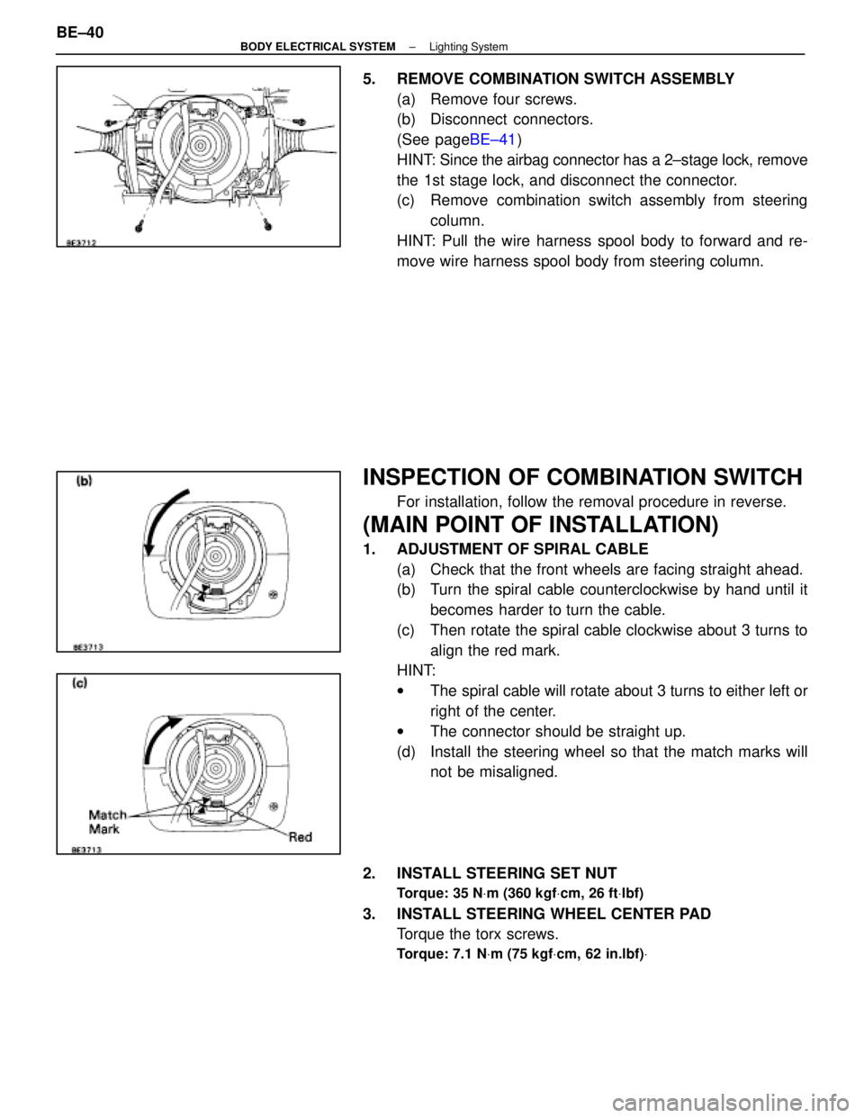
5. REMOVE COMBINATION SWITCH ASSEMBLY(a) Remove four screws.
(b) Disconnect connectors.
(See page BE±41)
HINT: Since the airbag connector has a 2±stage lock, remove
the 1st stage lock, and disconnect the connector.
(c) Remove combination switch assembly from steering column.
HINT: Pull the wire harness spool body to forward and re-
move wire harness spool body from steering column.
INSPECTION OF COMBINATION SWITCH
For installation, follow the removal procedure in reverse.
(MAIN POINT OF INSTALLATION)
1. ADJUSTMENT OF SPIRAL CABLE (a) Check that the front wheels are facing straight ahead.
(b) Turn the spiral cable counterclockwise by hand until itbecomes harder to turn the cable.
(c) Then rotate the spiral cable clockwise about 3 turns to align the red mark.
HINT:
w The spiral cable will rotate about 3 turns to either left or
right of the center.
w The connector should be straight up.
(d) Install the steering wheel so that the match marks will not be misaligned.
2. INSTALL STEERING SET NUT
Torque: 35 N Vm (360 kgf Vcm, 26 ft Vlbf)
3. INSTALL STEERING WHEEL CENTER PAD
Torque the torx screws.
Torque: 7.1 N Vm (75 kgf Vcm, 62 in.lbf) V
BE±40±
BODY ELECTRICAL SYSTEM Lighting System
WhereEverybodyKnowsYourName
Page 839 of 4087
5. REMOVE WIRE HARNESS CLAMPRemove three screws and wire harness clamp.
6. SEPARATE CONNECTOR (a) Pry loose two locking lugs.
(b) Separate two connectors from connector assembly.
7. REMOVE TERMINALS FROM CONNECTOR (32p connector)
(a) Pull out two inner terminal covers.
CAUTION: Do not remove terminal for AIRBAG connec-
tor (Yellow).
(b) From the open end, insert a miniature screwdriver
between the locking lug and terminal.
(c) Pry down the locking lug with the screwdriver and pull the terminal out from the rear.
8. REMOVE LIGHT CONTROL SWITCH (a) Remove the two screws, and separate the bracket from
switch body.
±
BODY ELECTRICAL SYSTEM Lighting SystemBE±43
WhereEverybodyKnowsYourName
Page 1236 of 4087
BO6847
NOTICE: True up the mounting section ofthe front airbag sensor very carefully and
accurately so that the sensor can bemounted at the correct angle.
Imaginary
Standard
Line
mm (in.)
(Two-Dimensional Distance)
Hote dia.
10 (0.39) nut
10 (0.33) nut
18 (0.71)
14 (0.55) nut 9 (0.35)
Name
Engine rear mounting member installation nut-front Propeller shaft center support bearing installation nut
Front floor reinforcement standard hole
Rear suspension member installation nut Rear spring support hole-front
Symbol
J, j
K, k
L, l
N, n
O, o
Hole dia.
9 (0.35)
9 (0.35)
8 (0.31) nut
13 y11 (0.51 y0.43)14 (0.55) nut
Name
Front crossmember working hole
Airbag front sensor installation hole
Airbag front sensor installation nut Front spring support hole = outer
Front suspension crossmember installation nut
Symbol
B, b
C, c
E, e
G, g H, h
UNDER BODY (Cont'd)
BODY DIMENSIONSDI-7
WhereEverybodyKnowsYourName
Page 1246 of 4087

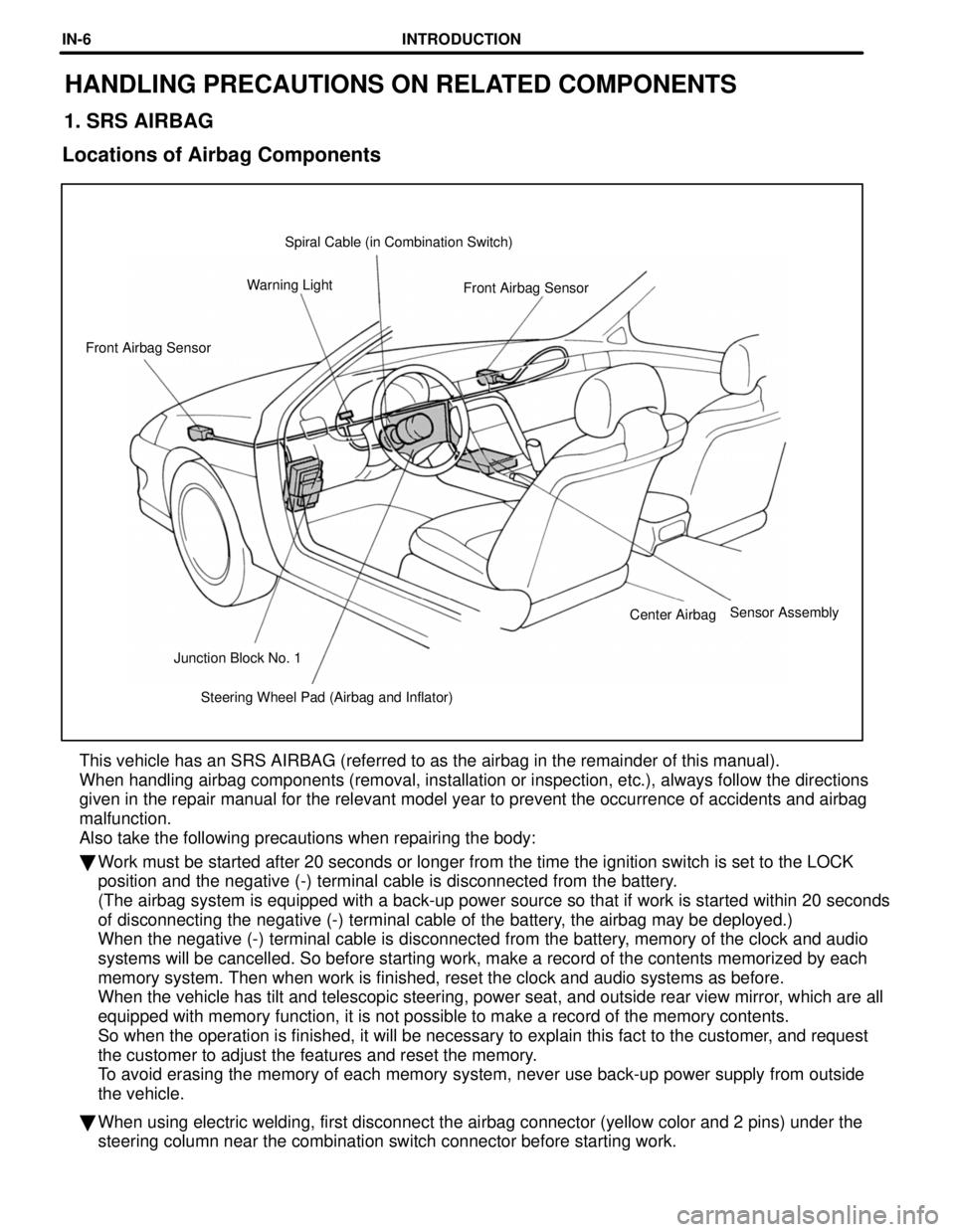
Steering Wheel Pad (Airbag and Inflator)
Junction Block No. 1 Center Airbag
Front Airbag Sensor
Front Airbag Sensor
Warning Light Spiral Cable (in Combination Switch)
HANDLING PRECAUTIONS ON RELATED COMPONENTS
1. SRS AIRBAG
Locations of Airbag Components
This vehicle has an SRS AIRBAG (referred to as the airbag in the remain\
der of this manual).
When handling airbag components (removal, installation or inspection, e\
tc.), always follow the directions
given in the repair manual for the relevant model year to prevent the oc\
currence of accidents and airbag
malfunction.
Also take the following precautions when repairing the body:
� Work must be started after 20 seconds or longer from the time the ignitio\
n switch is set to the LOCK
position and the negative (-) terminal cable is disconnected from the \
battery.
(The airbag system is equipped with a back-up power source so that if w\
ork is started within 20 seconds
of disconnecting the negative (-) terminal cable of the battery, the airbag may be deployed.)
When the negative (-) terminal cable is disconnected from the battery, memory of the clock and audio
systems will be cancelled. So before starting work, make a record of the\
contents memorized by each
memory system. Then when work is finished, reset the clock and audio sys\
tems as before.
When the vehicle has tilt and telescopic steering, power seat, and outsi\
de rear view mirror, which are all
equipped with memory function, it is not possible to make a record of th\
e memory contents.
So when the operation is finished, it will be necessary to explain this \
fact to the customer, and request
the customer to adjust the features and reset the memory.
To avoid erasing the memory of each memory system, never use back-up powe\
r supply from outside
the vehicle.
� When using electric welding, first disconnect the airbag connector (yel\
low color and 2 pins) under the
steering column near the combination switch connector before starting wo\
rk.
Sensor Assembly
INTRODUCTIONIN-6
WhereEverybodyKnowsYourName