Page 2636 of 4087

OKNG
OKNG
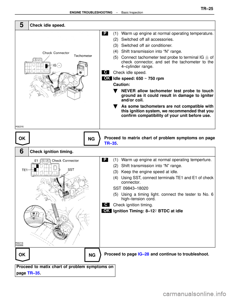
5Check idle speed.
C
OK
P(1) Warm up engine at normal operating temperature.
(2) Switched off all accessories.
(3) Switched off air conditioner.
(4) Shift transmission into ªNº range.
(5) Connect tachometer test probe to terminal IG � of
check connector, and set the tachometer to the
4±cylinder range.
Check idle speed.
Idle speed: 650 ~ 750 rpm
Caution:
�NEVER allow tachometer test probe to touch
ground as it could result in damage to igniter
and/or coil.
�As some tachometers are not compatible with
this ignition system, we recommended that you
confirm compatibility of your unit before use.
Proceed to matrix chart of problem symptoms on page
TR±35 .
6Check ignition timing.
C
OK
P(1) Warm up engine at normal operating temperture.
(2) Shift transmission into ªNº range.
(3) Keep the engine speed at idle.
(4) Using SST, connect terminals TE1 and E1 of check
connector.
SST 09843±18020
(5) Using a timing light. connect the tester to No. 6 high±tension cord.
Check ignition timing.
Ignition Timing: 8±12 � BTDC at idle
Proceed to page IG±28 and continue to troubleshoot.
Proceed to matix chart of problem symptoms on
page TR±35 .
±
ENGINE TROUBLESHOOTING Basic InspectionTR±25
WhereEverybodyKnowsYourName
Page 2637 of 4087
OKNG
OKNG
7Check fuel pressure.
C
P(1) Be sure that fuel is enough in tank.
(2) Turn ignition switch on.
(3) Using SST, connect terminals FP and + B of checkconnector.
SST 09843±18020
Check that pulsation damper screw rises up when termi-
nals are connected.
Caution:
Never make a mistake with the terminal connection
position as this will cause a malfunction.
Proceed to page FI±18 and continue to troubleshoot.
8Check for spark.
C
Hint
Disconnect the high±tension cord from the distributor
and, hold the end about 12.5 mm (1/2º) from the ground,
see if spark occurs while the engine is being cranked.
To prevent excessive fuel injected from the injectors dur-
ing this test, Don't crank the engine for more than 1 ± 2
seconds at a time.
Proceed to the page IG±6 and continue to troubleshoot.
Proceed to matix chart of problem systems on
page TR±35 .
TR±26±
ENGINE TROUBLESHOOTING Basic Inspection
WhereEverybodyKnowsYourName
Page 2638 of 4087
PARTS LOCATION
±
ENGINE TROUBLESHOOTING Parts locationTR±27
WhereEverybodyKnowsYourName
Page 2639 of 4087
WIRING DIAGRAM
TR±28±
ENGINE TROUBLESHOOTING Wiring Diagram
WhereEverybodyKnowsYourName
Page 2640 of 4087
±
ENGINE TROUBLESHOOTING Wiring DiagramTR±29
WhereEverybodyKnowsYourName
Page 2641 of 4087

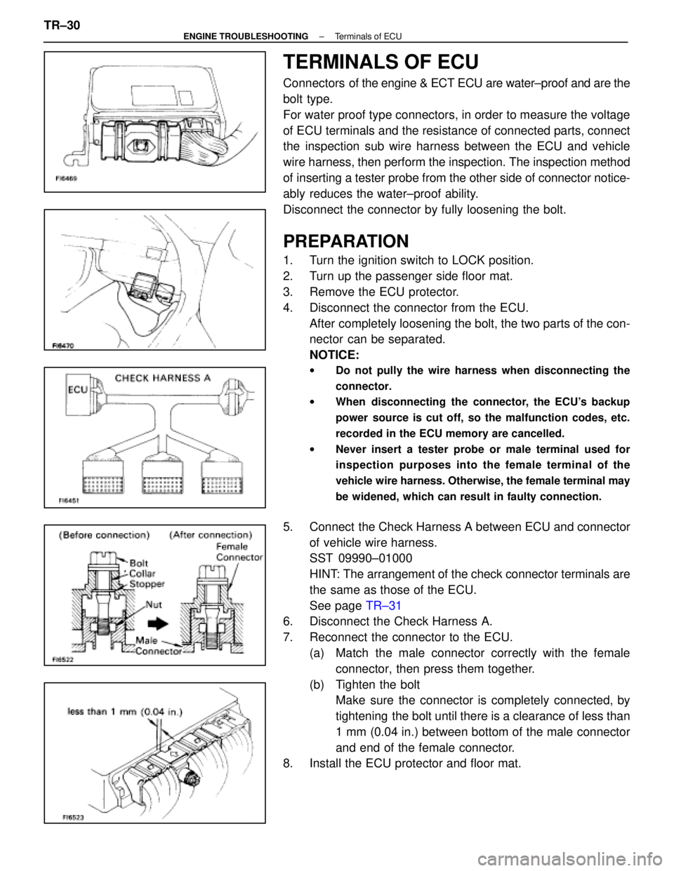
TERMINALS OF ECU
Connectors of the engine & ECT ECU are water±proof and are the
bolt type.
For water proof type connectors, in order to measure the voltage
of ECU terminals and the resistance of connected parts, connect
the inspection sub wire harness between the ECU and vehicle
wire harness, then perform the inspection. The inspection method
of inserting a tester probe from the other side of connector notice-
ably reduces the water±proof ability.
Disconnect the connector by fully loosening the bolt.
PREPARATION
1. Turn the ignition switch to LOCK position.
2. Turn up the passenger side floor mat.
3. Remove the ECU protector.
4. Disconnect the connector from the ECU. After completely loosening the bolt, the two parts of the con-
nector can be separated.
NOTICE:
w Do not pully the wire harness when disconnecting the
connector.
w When disconnecting the connector, the ECU's backup
power source is cut off, so the malfunction codes, etc.
recorded in the ECU memory are cancelled.
w Never insert a tester probe or male terminal used for
inspection purposes into the female terminal of the
vehicle wire harness. Otherwise, the female terminal may
be widened, which can result in faulty connection.
5. Connect the Check Harness A between ECU and connector
of vehicle wire harness.
SST 09990±01000
HINT: The arrangement of the check connector terminals are
the same as those of the ECU.
See page TR±31
6. Disconnect the Check Harness A.
7. Reconnect the connector to the ECU.
(a) Match the male connector correctly with the femaleconnector, then press them together.
(b) Tighten the bolt Make sure the connector is completely connected, by
tightening the bolt until there is a clearance of less than
1 mm (0.04 in.) between bottom of the male connector
and end of the female connector.
8. Install the ECU protector and floor mat.
TR±30
±
ENGINE TROUBLESHOOTING Terminals of ECU
WhereEverybodyKnowsYourName
Page 2642 of 4087
TERMINALS OF ECU
±
ENGINE TROUBLESHOOTING Terminals of ECUTR±31
WhereEverybodyKnowsYourName
Page 2643 of 4087
TERMINALS OF ECU (Cont'd)
TR±32±
ENGINE TROUBLESHOOTING Terminals of ECU
WhereEverybodyKnowsYourName