Page 2564 of 4087
REMOVAL OF OIL PUMP
(See Components on page LU±8)
HINT: When repairing the oil pump, the oil pan and strainer
should be removed and cleaned.
1. REMOVE ENGINE WITH TRANSMISSION (See pages EM±118 to 128)
2. SEPARATE ENGINE AND TRANSMISSION (See pages EM±129 to 130)
3. INSTALL ENGINE TO ENGINE STAND FOR REMOVAL
4. REMOVE TIMING BELT (See steps 8 to 35 on pages EM±36 to 43)
5. REMOVE NO.2 IDLER PULLEY, NO.1 IDLER PULLEY AND CRANKSHAFT TIMING PULLEY
(See steps 36 to 38 on page EM±44)
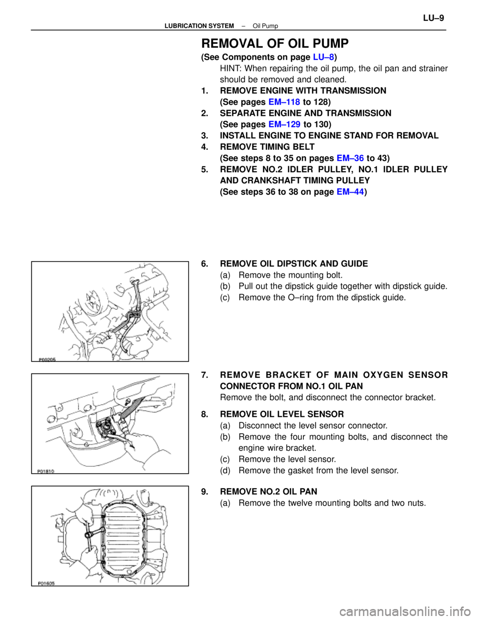
6. REMOVE OIL DIPSTICK AND GUIDE (a) Remove the mounting bolt.
(b) Pull out the dipstick guide together with dipstick guide.
(c) Remove the O±ring from the dipstick guide.
7. REMOVE BRACKET OF MAIN OXYGEN SENSOR CONNECTOR FROM NO.1 OIL PAN
Remove the bolt, and disconnect the connector bracket.
8. REMOVE OIL LEVEL SENSOR (a) Disconnect the level sensor connector.
(b) Remove the four mounting bolts, and disconnect theengine wire bracket.
(c) Remove the level sensor.
(d) Remove the gasket from the level sensor.
9. REMOVE NO.2 OIL PAN (a) Remove the twelve mounting bolts and two nuts.
±
LUBRICATION SYSTEM Oil PumpLU±9
WhereEverybodyKnowsYourName
Page 2574 of 4087
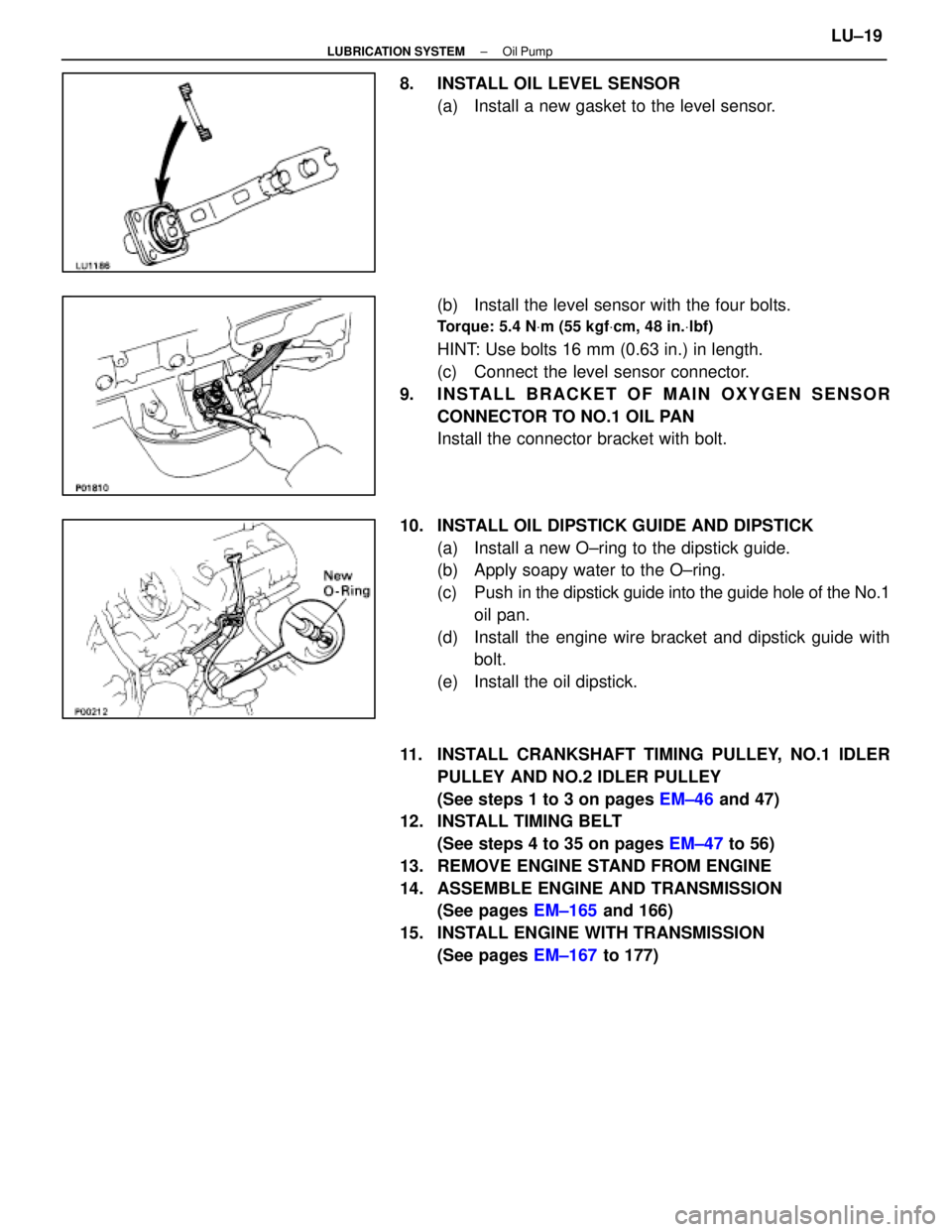
8. INSTALL OIL LEVEL SENSOR(a) Install a new gasket to the level sensor.
(b) Install the level sensor with the four bolts.
Torque: 5.4 N Vm (55 kgf Vcm, 48 in. Vlbf)
HINT: Use bolts 16 mm (0.63 in.) in length.
(c) Connect the level sensor connector.
9. INSTALL BRACKET OF MAIN OXYGEN SENSOR CONNECTOR TO NO.1 OIL PAN
Install the connector bracket with bolt.
10. INSTALL OIL DIPSTICK GUIDE AND DIPSTICK (a) Install a new O±ring to the dipstick guide.
(b) Apply soapy water to the O±ring.
(c) Push in the dipstick guide into the guide hole of the No.1
oil pan.
(d) Install the engine wire bracket and dipstick guide with bolt.
(e) Install the oil dipstick.
11. INSTALL CRANKSHAFT TIMING PULLEY, NO.1 IDLER PULLEY AND NO.2 IDLER PULLEY
(See steps 1 to 3 on pages EM±46 and 47)
12. INSTALL TIMING BELT
(See steps 4 to 35 on pages EM±47 to 56)
13. REMOVE ENGINE STAND FROM ENGINE
14. ASSEMBLE ENGINE AND TRANSMISSION (See pages EM±165 and 166)
15. INSTALL ENGINE WITH TRANSMISSION (See pages EM±167 to 177)
±
LUBRICATION SYSTEM Oil PumpLU±19
WhereEverybodyKnowsYourName
Page 2636 of 4087
OKNG
OKNG
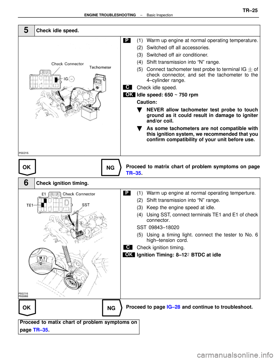
5Check idle speed.
C
OK
P(1) Warm up engine at normal operating temperature.
(2) Switched off all accessories.
(3) Switched off air conditioner.
(4) Shift transmission into ªNº range.
(5) Connect tachometer test probe to terminal IG � of
check connector, and set the tachometer to the
4±cylinder range.
Check idle speed.
Idle speed: 650 ~ 750 rpm
Caution:
�NEVER allow tachometer test probe to touch
ground as it could result in damage to igniter
and/or coil.
�As some tachometers are not compatible with
this ignition system, we recommended that you
confirm compatibility of your unit before use.
Proceed to matrix chart of problem symptoms on page
TR±35 .
6Check ignition timing.
C
OK
P(1) Warm up engine at normal operating temperture.
(2) Shift transmission into ªNº range.
(3) Keep the engine speed at idle.
(4) Using SST, connect terminals TE1 and E1 of check
connector.
SST 09843±18020
(5) Using a timing light. connect the tester to No. 6 high±tension cord.
Check ignition timing.
Ignition Timing: 8±12 � BTDC at idle
Proceed to page IG±28 and continue to troubleshoot.
Proceed to matix chart of problem symptoms on
page TR±35 .
±
ENGINE TROUBLESHOOTING Basic InspectionTR±25
WhereEverybodyKnowsYourName
Page 3398 of 4087
OKNG
OKNG
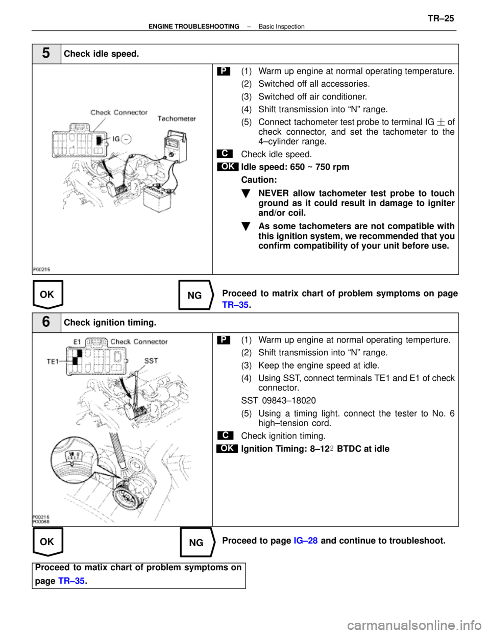
5Check idle speed.
C
OK
P(1) Warm up engine at normal operating temperature.
(2) Switched off all accessories.
(3) Switched off air conditioner.
(4) Shift transmission into ªNº range.
(5) Connect tachometer test probe to terminal IG � of
check connector, and set the tachometer to the
4±cylinder range.
Check idle speed.
Idle speed: 650 ~ 750 rpm
Caution:
�NEVER allow tachometer test probe to touch
ground as it could result in damage to igniter
and/or coil.
�As some tachometers are not compatible with
this ignition system, we recommended that you
confirm compatibility of your unit before use.
Proceed to matrix chart of problem symptoms on page
TR±35 .
6Check ignition timing.
C
OK
P(1) Warm up engine at normal operating temperture.
(2) Shift transmission into ªNº range.
(3) Keep the engine speed at idle.
(4) Using SST, connect terminals TE1 and E1 of check
connector.
SST 09843±18020
(5) Using a timing light. connect the tester to No. 6 high±tension cord.
Check ignition timing.
Ignition Timing: 8±12 � BTDC at idle
Proceed to page IG±28 and continue to troubleshoot.
Proceed to matix chart of problem symptoms on
page TR±35 .
±
ENGINE TROUBLESHOOTING Basic InspectionTR±25
WhereEverybodyKnowsYourName
Page 3610 of 4087
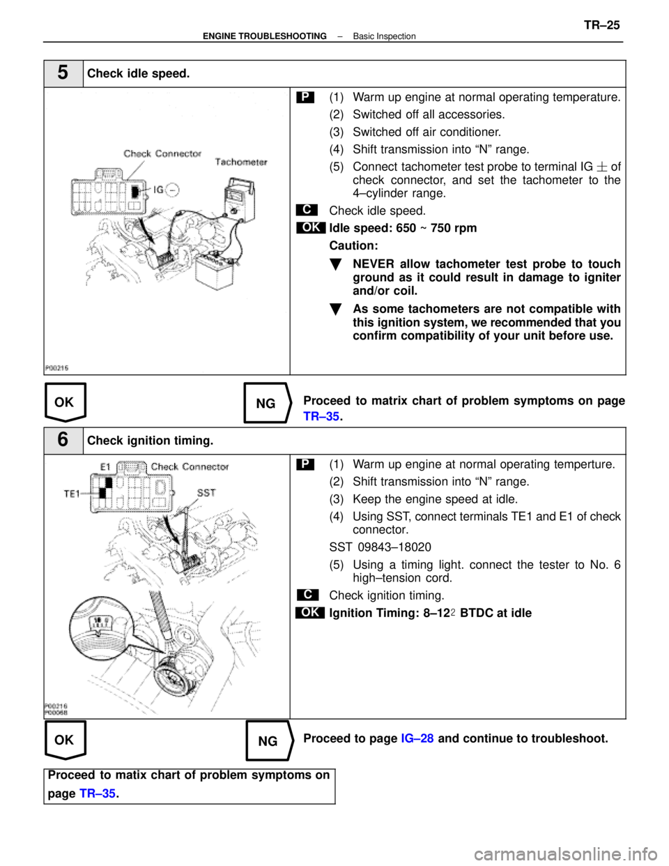
OKNG
OKNG
5Check idle speed.
C
OK
P(1) Warm up engine at normal operating temperature.
(2) Switched off all accessories.
(3) Switched off air conditioner.
(4) Shift transmission into ªNº range.
(5) Connect tachometer test probe to terminal IG � of
check connector, and set the tachometer to the
4±cylinder range.
Check idle speed.
Idle speed: 650 ~ 750 rpm
Caution:
�NEVER allow tachometer test probe to touch
ground as it could result in damage to igniter
and/or coil.
�As some tachometers are not compatible with
this ignition system, we recommended that you
confirm compatibility of your unit before use.
Proceed to matrix chart of problem symptoms on page
TR±35 .
6Check ignition timing.
C
OK
P(1) Warm up engine at normal operating temperture.
(2) Shift transmission into ªNº range.
(3) Keep the engine speed at idle.
(4) Using SST, connect terminals TE1 and E1 of check
connector.
SST 09843±18020
(5) Using a timing light. connect the tester to No. 6 high±tension cord.
Check ignition timing.
Ignition Timing: 8±12 � BTDC at idle
Proceed to page IG±28 and continue to troubleshoot.
Proceed to matix chart of problem symptoms on
page TR±35 .
±
ENGINE TROUBLESHOOTING Basic InspectionTR±25
WhereEverybodyKnowsYourName
Page 3901 of 4087

66
.
ENGINE CONTROL
THIS SYSTEM UTILIZES AN ECU AND MAINTAINS OVERALL CONTROL OF THE ENGINE, TRANSMISSION AND SO ON. AN OUTLINE O\
F
THE ENGINE CONTROL IS EXPLAINED HERE.
1. INPUT SIGNALS
(1) WATER TEMP. SIGNAL CIRCUITTHE WATER TEMP. SENSOR DETECTS THE ENGINE COOLANT TEMP. AND HAS A BUILT±IN THERMISTOR WITH A RESISTANCE
WHICH VARIES ACCORDING TO THE WATER TEMP. THE WATER TEMP. IS INPUT INTO TERMINAL THW OF ENGINE CONTROL
ECU AS A CONTROL SIGNAL.
(2) INTAKE AIR TEMP. SIGNAL CIRCUIT THE INTAKE AIR TEMP. SENSOR IS INSTALLED IN THE AIR FLOW METER AND DETECTS THE INTAKE AIR TEMP., WHICH IS INPUT
AS A CONTROL SIGNAL TO TERMINAL THA OF ENGINE CONTROL ECU.
(3) OXYGEN SENSOR SIGNAL CIRCUIT THE OXYGEN DENSITY IN THE EXHAUST EMISSION IS DETECTED AND INPUT AS A CONTR\
OL SIGNAL FROM THE OXYGEN
SENSOR NO. 1 AND NO. 2 TO TERMINALS OX1, OX2 OF THE ECU AND FROM THE OXYGEN SENSOR SUB (FOR CALIFORNIA) TO
TERMINAL OX3 OF THE ECU.
TO STABILIZE DETECTION PERFORMANCE BY THE OXYGEN SENSOR SUB (FOR CALIFORNIA)\
IS WARMED. THIS HEATER IS
ALSO CONTROLLED BY THE ECU (HT).
(4) RPM SIGNAL CIRCUIT CRANKSHAFT POSITION IS DETECTED BY THE PICK±UP COIL INSTALLED INSIDE THE DISTRIBUTOR. CRANKSHAFT POSITION
IS INPUT AS A CONTROL SIGNAL TO TERMINALS G1 AND G2 OF THE ECU, AND RPM IS INPUT TO TERMINAL NE.
(5) THROTTLE SIGNAL CIRCUIT THE THROTTLE POSITION SENSOR DETECTS THE THROTTLE VALVE OPENING ANGLE AS A CONTROL SIGNAL, WHICH IS
INPUT INTO TERMINAL VTA1 OF THE ECU. WHEN THE VALVE IS COMPLETELY CLOSED, THE CONTROL SIGNAL IS INPUT INTO
TERMINAL IDL1 .
(6) VEHICLE SPEED CIRCUIT THE VEHICLE SPEED IS DETECTED BY SPEED SENSOR NO. 1 INSTALLED IN THE TRANSMISSION AND THE SIGNAL IS INPUT TO
TERMINAL SPD OF THE ECU VIA THE COMB. METER.
(7) NEUTRAL START SIGNAL CIRCUIT THE NEUTRAL START SW DETECTS WHETHER THE SHIFT POSITION IS IN NEUTRAL OR NOT, AND THE SIGNAL IS INPUT INTO
TERMINAL NSW OF THE ECU.
(8) AIRCONDITIONING SW SIGNAL CIRCUIT THE OPERATING VOLTAGE OF THE A/C MAGNETIC CLUTCH IS DETECTED AND THE SIGNAL IS INPUT INTO TERMINAL ACMG OF
ECU AS A CONTROL SIGNAL.
(9) BATTERY SIGNAL CIRCUIT VOLTAGE IS CONSTANTLY APPLIED TO TERMINAL BATT OF THE ECU. WITH THE IGNITION SW TURNED ON, THE VOLTAGE FOR
ECU START±UP POWER SUPPLY IS APPLIED TO TERMINALS +B AND +B1 OF ECU VIA EFI MAIN RELAY.
THE CURRENT FLOWING THROUGH THE IGN FUSE FLOWS TO TERMINAL IGSW OF THE ECU.
(10) INTAKE AIR VOLUME SIGNAL CIRCUIT INTAKE AIR VOLUME IS DETECTED BY THE AIR FLOW METER AND THE SIGNAL IS INPUT TO TERMINAL KS OF THE ECU AS A
CONTROL SIGNAL.
(11) STOP LIGHT SW SIGNAL CIRCUIT THE STOP LIGHT SW IS USED TO DETECT WHETHER OR NOT THE VEHICLE IS BRAKING AND THE SIGNAL IS INPUT INTO
TERMINAL STP OF THE ECU AS A CONTROL SIGNAL.
(12) STA SIGNAL CIRCUIT TO CONFIRM WHETHER THE ENGINE IS CRANKING, THE VOLTAGE APPLIED TO THE STARTER MOTOR DURING CRANKING IS
DETECTED AND THE SIGNAL IS INPUT INTO TERMINAL STA OF THE ECU AS A CONTROL SIGNAL.
(13) ENGINE KNOCK SIGNAL CIRCUIT ENGINE KNOCKING IS DETECTED BY KNOCK SENSOR NO. 1 AND NO. 2 AND THE SIGN\
AL IS INPUT INTO TERMINALS KNK1 AND
KNK2 AS A CONTROL SIGNAL.
SYSTEM OUTLINE
WhereEverybodyKnowsYourName