Page 2575 of 4087
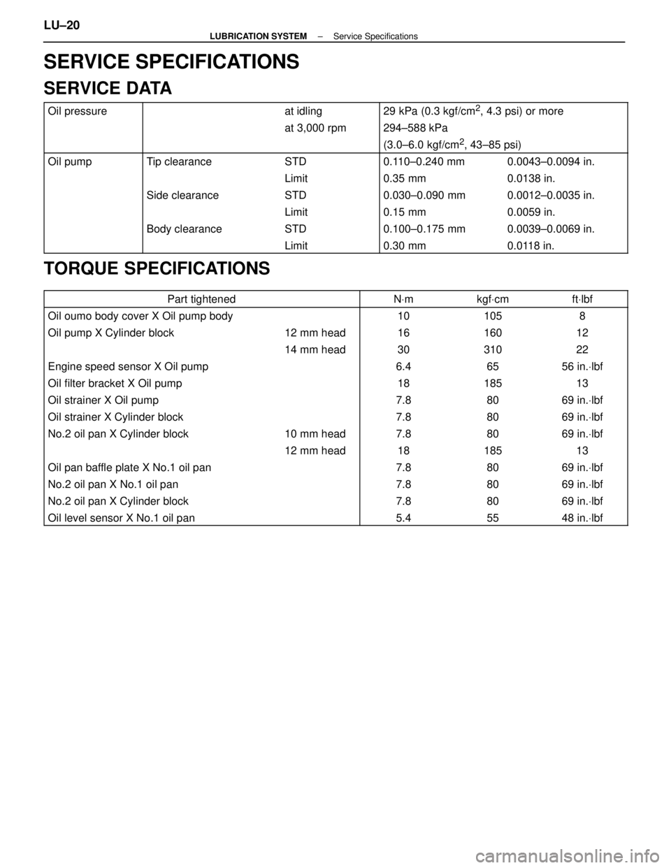
SERVICE SPECIFICATIONS
SERVICE DATA
Oil pressureat idling29 kPa (0.3 kgf/cm2, 4.3 psi) or more
at 3,000 rpm 294±588 kPa
(3.0±6.0 kgf/cm2, 43±85 psi)
Oil pumpTip clearanceSTD0.110±0.240 mm0.0043±0.0094 in.
Limit 0.35 mm0.0138 in.
Side clearanceSTD 0.030±0.090 mm0.0012±0.0035 in.
Limit 0.15 mm0.0059 in.
Body clearanceSTD 0.100±0.175 mm0.0039±0.0069 in.
Limit0.30 mm0.0118 in.
TORQUE SPECIFICATIONS
Part tightenedNVmkgf Vcmft Vlbf
Oil oumo body cover X Oil pump body101058
Oil pump X Cylinder block12 mm head 16160 12
14 mm head 30310 22
Engine speed sensor X Oil pump6.465 56 in. Vlbf
Oil filter bracket X Oil pump18185 13
Oil strainer X Oil pump7.880 69 in. Vlbf
Oil strainer X Cylinder block7.880 69 in. Vlbf
No.2 oil pan X Cylinder block10 mm head 7.880 69 in. Vlbf
12 mm head 18185 13
Oil pan baffle plate X No.1 oil pan7.880 69 in. Vlbf
No.2 oil pan X No.1 oil pan7.880 69 in. Vlbf
No.2 oil pan X Cylinder block7.880 69 in. Vlbf
Oil level sensor X No.1 oil pan5.45548 in. Vlbf
LU±20±
LUBRICATION SYSTEM Service Specifications
WhereEverybodyKnowsYourName
Page 2635 of 4087
YESNO
NOYES
YES
NO
OKNG
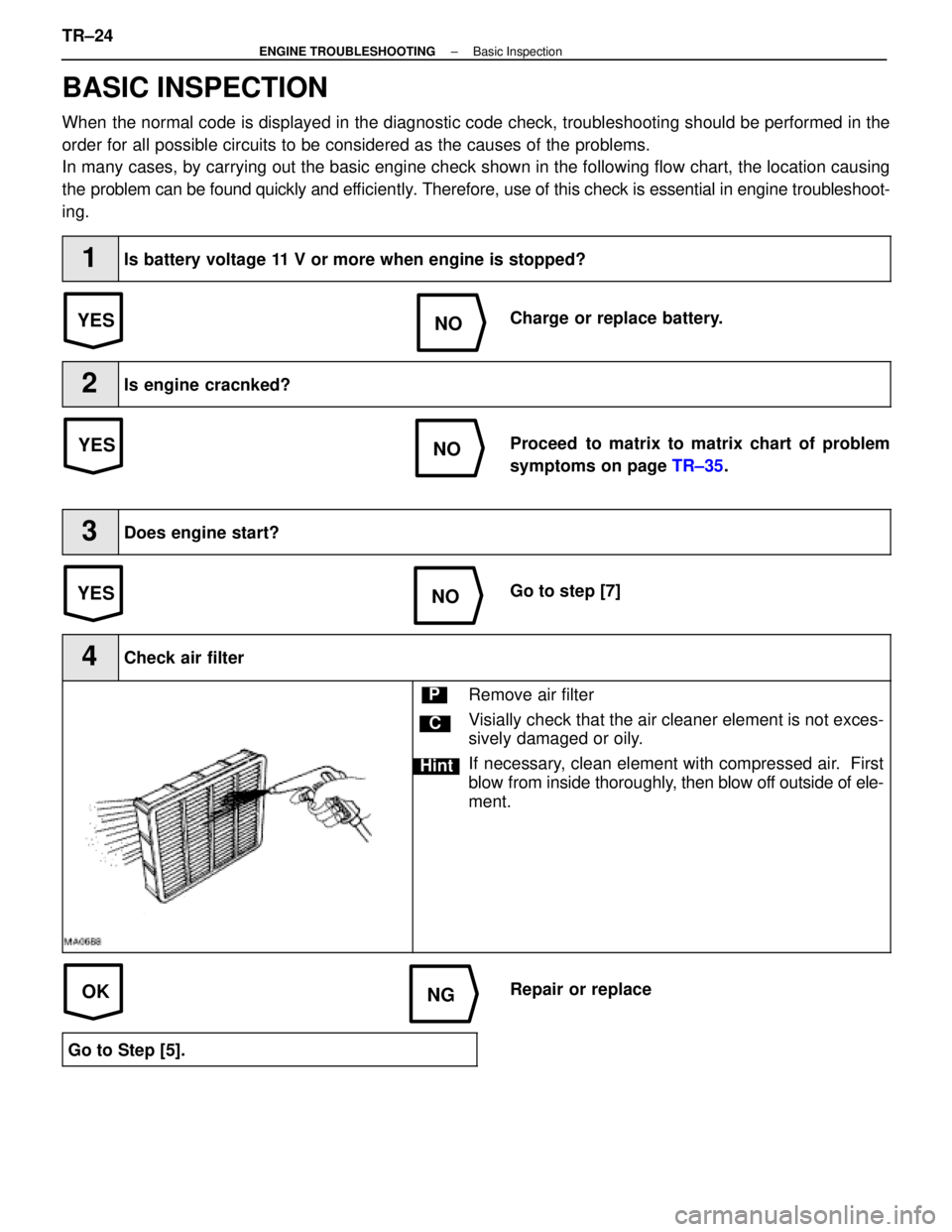
BASIC INSPECTION
When the normal code is displayed in the diagnostic code check, troubleshoot\
ing should be performed in the
order for all possible circuits to be considered as the causes of the pr\
oblems.
In many cases, by carrying out the basic engine check shown in the follo\
wing flow chart, the location causing
the problem can be found quickly and ef ficiently. Therefore, use of this check is essential in engine troubleshoot-
ing.
1Is battery voltage 11 V or more when engine is stopped?
Charge or replace battery.
2Is engine cracnked?
Proceed to matrix to matrix chart of problem
symptoms on page TR±35.
3Does engine start?
Go to step [7]
4Check air filter
C
Hint
PRemove air filter
Visially check that the air cleaner element is not exces-
sively damaged or oily.
If necessary, clean element with compressed air. First
blow from inside thoroughly, then blow off outside of ele-
ment.
Repair or replace
Go to Step [5].
TR±24±
ENGINE TROUBLESHOOTING Basic Inspection
WhereEverybodyKnowsYourName
Page 2813 of 4087
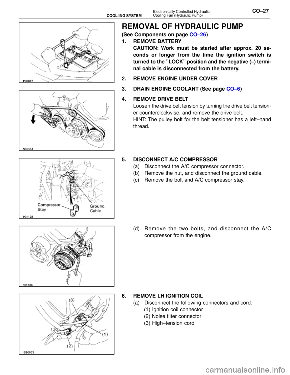
REMOVAL OF HYDRAULIC PUMP
(See Components on page CO±26)
1. REMOVE BATTERY CAUTION: Work must be started after approx. 20 se-
conds or longer from the time the ignition switch is
turned to the ºLOCKº position and the negative (±) termi-
nal cable is disconnected from the battery.
2. REMOVE ENGINE UNDER COVER
3. DRAIN ENGINE COOLANT (See page CO±6)
4. REMOVE DRIVE BELT Loosen the drive belt tension by turning the drive belt tension-
er counterclockwise, and remove the drive belt.
HINT: The pulley bolt for the belt tensioner has a left±hand
thread.
5. DISCONNECT A/C COMPRESSOR (a) Disconnect the A/C compressor connector.
(b) Remove the nut, and disconnect the ground cable.
(c) Remove the bolt and A/C compressor stay.
(d) R e m o v e t h e t w o b o l t s , a n d d i s c onnect the A/C
compressor from the engine.
6. REMOVE LH IGNITION COIL (a) Disconnect the following connectors and cord:(1) Ignition coil connector
(2) Noise filter connector
(3) High±tension cord
±
COOLIING SYSTEM Electronically Controlled Hydraulic
Cooling Fan (Hydraulic Pump)CO±27
WhereEverybodyKnowsYourName
Page 2820 of 4087
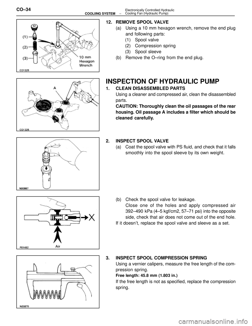
12. REMOVE SPOOL VALVE(a) Using a 10 mm hexagon wrench, remove the end plugand following parts:
(1) Spool valve
(2) Compression spring
(3) Spool sleeve
(b) Remove the O±ring from the end plug.
INSPECTION OF HYDRAULIC PUMP
1. CLEAN DISASSEMBLED PARTS Using a cleaner and compressed air, clean the disassembled
parts.
CAUTION: Thoroughly clean the oil passages of the rear
housing. Oil passage A includes a filter which should be
cleaned carefully.
2. INSPECT SPOOL VALVE (a) Coat the spool valve with PS fluid, and check that it falls
smoothly into the spool sleeve by its own weight.
(b) Check the spool valve for leakage. Close one of the holes and apply compressed air
392±490 kPa (4±5 kgf/cm2, 57±71 psi) into the opposite
side, check that air does not come out of the end hole.
If it doesn't, replace the spool valve and sleeve as a set.
3. INSPECT SPOOL COMPRESSION SPRING Using a vernier calipers, measure the free length of the com-
pression spring.
Free length: 45.8 mm (1.803 in.)
If the free length is not as specified, replace the compression
spring.
CO±34
±
COOLIING SYSTEM Electronically Controlled Hydraulic
Cooling Fan (Hydraulic Pump)
WhereEverybodyKnowsYourName
Page 2831 of 4087
14. INSTALL IGNITION COIL(a) Install the ignition coil with the two bolts.
(b) Connect the following connectors and cord:(1) Ignition coil connector
(2) Noise filter connector
(3) High±tension cord
15. INSTALL A/C COMPRESSOR (a) In sta ll th e A/C co mp re sso r, co mp re sso r sta y an dground cable with the three bolts and nut.
Torque: Bolt 49 N Vm (500 kgf Vcm, 36 ft Vlbf)
Nut 29 N Vm (300 kgf Vcm, 22 ft Vlbf)
(b) Connect the A/C compressor connector.
16. INSTALL DRIVE BELT Install the drive belt by turning the drive belt tensioner coun-
terclockwise.
HINT: The pulley bolt for the belt tensioner has a left±hand
thread.
17. CONNECT RADIATOR HOSE TO WATER INLET
±
COOLIING SYSTEM Electronically Controlled Hydraulic Cooling Fan
(Hydraulic Pump)CO±45
WhereEverybodyKnowsYourName
Page 2851 of 4087
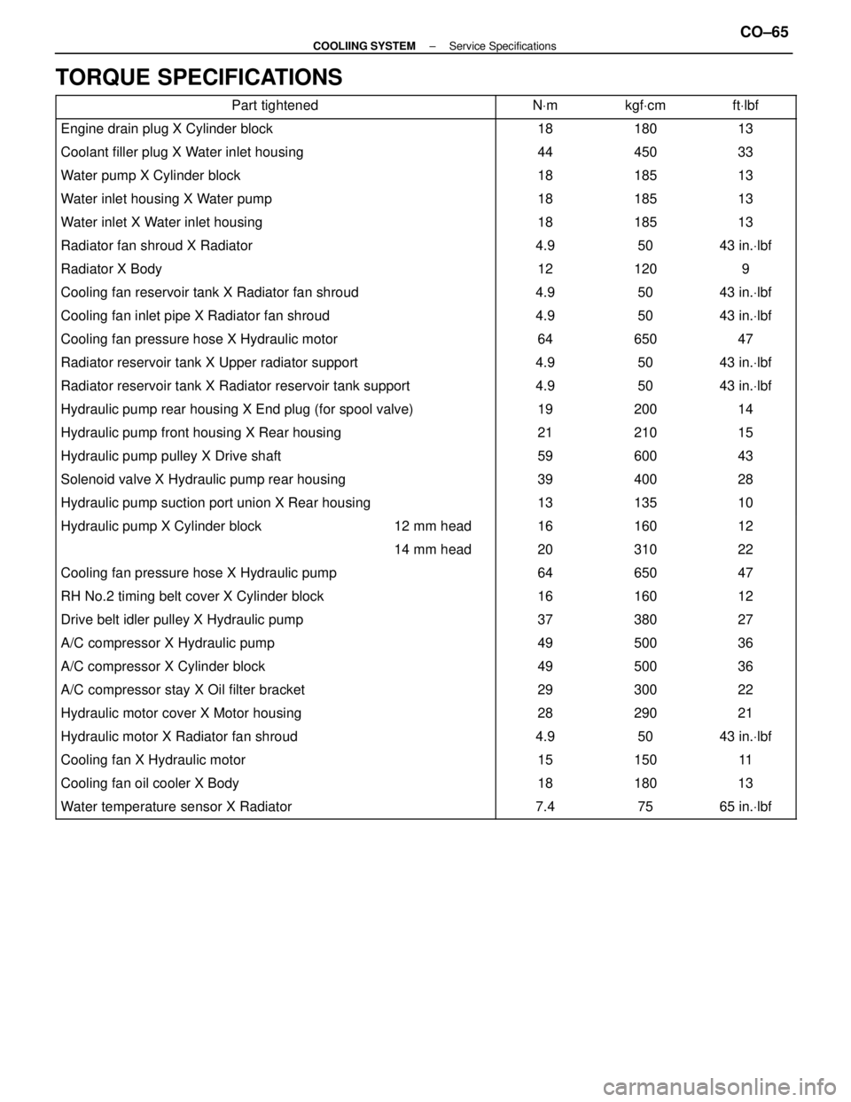
TORQUE SPECIFICATIONS
Part tightenedNVmkgf Vcmft Vlbf
Engine drain plug X Cylinder block1818013
Coolant filler plug X Water inlet housing44450 33
Water pump X Cylinder block18185 13
Water inlet housing X Water pump18185 13
Water inlet X Water inlet housing18185 13
Radiator fan shroud X Radiator4.950 43 in. Vlbf
Radiator X Body12120 9
Cooling fan reservoir tank X Radiator fan shroud4.950 43 in. Vlbf
Cooling fan inlet pipe X Radiator fan shroud4.950 43 in. Vlbf
Cooling fan pressure hose X Hydraulic motor64650 47
Radiator reservoir tank X Upper radiator support4.950 43 in. Vlbf
Radiator reservoir tank X Radiator reservoir tank support4.950 43 in. Vlbf
Hydraulic pump rear housing X End plug (for spool valve)19200 14
Hydraulic pump front housing X Rear housing21210 15
Hydraulic pump pulley X Drive shaft59600 43
Solenoid valve X Hydraulic pump rear housing39400 28
Hydraulic pump suction port union X Rear housing13135 10
����������������� �����������������Hydraulic pump X Cylinder block������ ������12 mm head����� �����16������ ������160������ ������12
����������������� ����������������������� ������14 mm head����� �����20������ ������310������ ������22
������������������\
���� ������������������\
����Cooling fan pressure hose X Hydraulic pump����� �����64������ ������650������ ������47
������������������\
���� ������������������\
����RH No.2 timing belt cover X Cylinder block����� �����16������ ������160������ ������12
������������������\
���� ������������������\
����Drive belt idler pulley X Hydraulic pump����� �����37������ ������380������ ������27
������������������\
���� ������������������\
����A/C compressor X Hydraulic pump����� �����49������ ������500������ ������36
������������������\
���� ������������������\
����A/C compressor X Cylinder block����� �����49������ ������500������ ������36������������������\
���� ������������������\
����A/C compressor stay X Oil filter bracket����� �����29������ ������300������ ������22������������������\
���� ������������������\
����Hydraulic motor cover X Motor housing����� �����28������ ������290������ ������21������������������\
���� �
������������������\
���
������������������\
����Hydraulic motor X Radiator fan shroud
����� �
����
�����4.9
������ �
�����
������50
������ �
�����
������43 in.
Vlbf
������������������\
���� ������������������\
����Cooling fan X Hydraulic motor����� �����15������ ������150������ ������11
������������������\
���� ������������������\
����Cooling fan oil cooler X Body����� �����18������ ������180������ ������13
������������������\
���� ������������������\
����Water temperature sensor X Radiator����� �����7.4������ ������75������ ������65 in. Vlbf
±
COOLIING SYSTEM Service SpecificationsCO±65
WhereEverybodyKnowsYourName
Page 3397 of 4087
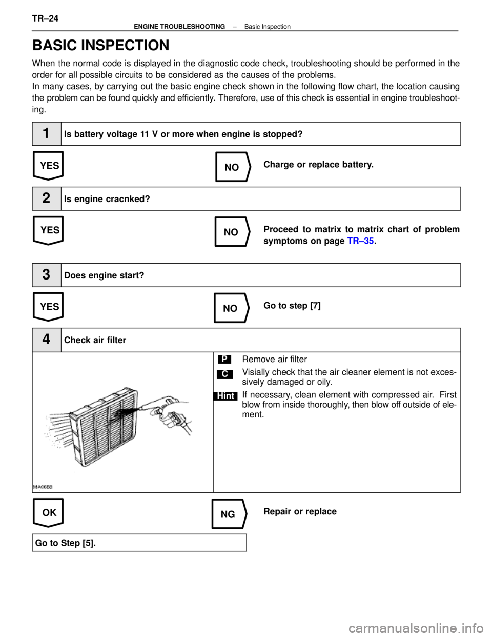
YESNO
NOYES
YES
NO
OKNG
BASIC INSPECTION
When the normal code is displayed in the diagnostic code check, troubleshoot\
ing should be performed in the
order for all possible circuits to be considered as the causes of the pr\
oblems.
In many cases, by carrying out the basic engine check shown in the follo\
wing flow chart, the location causing
the problem can be found quickly and ef ficiently. Therefore, use of this check is essential in engine troubleshoot-
ing.
1Is battery voltage 11 V or more when engine is stopped?
Charge or replace battery.
2Is engine cracnked?
Proceed to matrix to matrix chart of problem
symptoms on page TR±35.
3Does engine start?
Go to step [7]
4Check air filter
C
Hint
PRemove air filter
Visially check that the air cleaner element is not exces-
sively damaged or oily.
If necessary, clean element with compressed air. First
blow from inside thoroughly, then blow off outside of ele-
ment.
Repair or replace
Go to Step [5].
TR±24±
ENGINE TROUBLESHOOTING Basic Inspection
WhereEverybodyKnowsYourName
Page 3609 of 4087
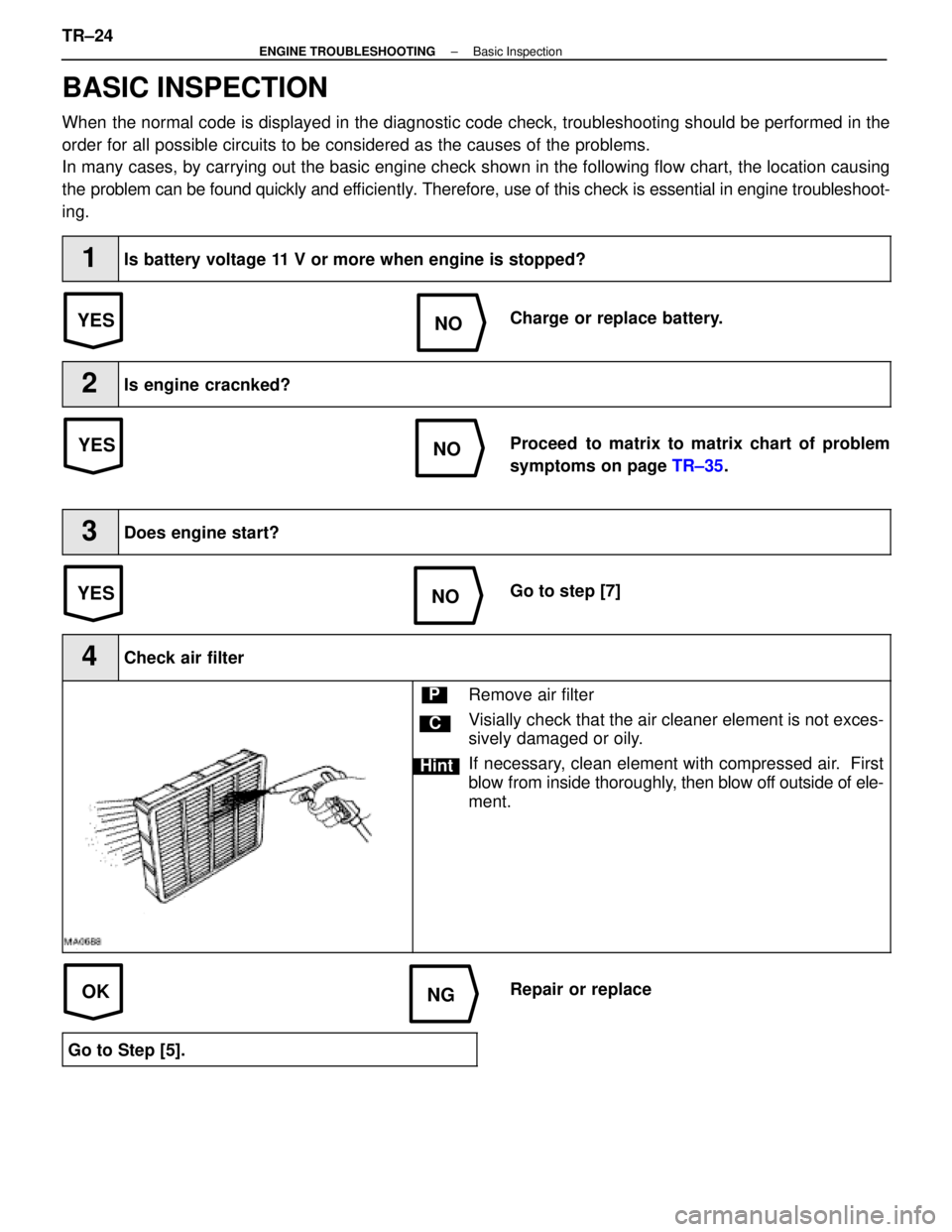
YESNO
NOYES
YES
NO
OKNG
BASIC INSPECTION
When the normal code is displayed in the diagnostic code check, troubleshoot\
ing should be performed in the
order for all possible circuits to be considered as the causes of the pr\
oblems.
In many cases, by carrying out the basic engine check shown in the follo\
wing flow chart, the location causing
the problem can be found quickly and ef ficiently. Therefore, use of this check is essential in engine troubleshoot-
ing.
1Is battery voltage 11 V or more when engine is stopped?
Charge or replace battery.
2Is engine cracnked?
Proceed to matrix to matrix chart of problem
symptoms on page TR±35.
3Does engine start?
Go to step [7]
4Check air filter
C
Hint
PRemove air filter
Visially check that the air cleaner element is not exces-
sively damaged or oily.
If necessary, clean element with compressed air. First
blow from inside thoroughly, then blow off outside of ele-
ment.
Repair or replace
Go to Step [5].
TR±24±
ENGINE TROUBLESHOOTING Basic Inspection
WhereEverybodyKnowsYourName