Page 238 of 4087
Description
The SRS (Supplemental Restraint System) airbag, together with
the seat belt, is designed to help protect the driver. In a collision,
the airbag sensors detect the shock, and if the front±to±rear shock
is greater than a specified value, an airbag stored in the steering
wheel pad is inflated instantaneously to help reduce the shock to
the driver.
LOCATION OF COMPONENTS
AB±24SRS AIRBAG ± Troubleshooting
WhereEverybodyKnowsYourName
Page 240 of 4087
NOTICE: When connecting the battery after clearing the malfunction code, always\
do it with the igni-
tion switch in LOCK position. When the battery has been reconnected, turn the ignition switch to
ACC or ON position after at least 2 seconds have elapsed.
If the battery is reconnected with the ignition switch in ACC or ON posi\
tion, or the ignition switch
is turned to ACC or ON within 2 seconds of connecting the battery, it is possible that the diagnosis
system will not operate normally.
HINT: Determine the malfunction in the airbag system in step [ 6 ] by whethe\
r or not a malfunction code
other than code 41 is output.
7. DIAGNOSTIC CODE CHART Proceed to the appropriate flow chart in step [ 8 ] in accordance with the malfunction code found in step
[ 5 ] or [ 6 ].
8. CIRCUIT INSPECTION [ 9 ] REPAIR Find out if the problem lies in a sensor, actuator or wire harness and connector, and repair the problem.
After the problem part is repaired, reinstall the disassembled parts. Do not \
start work until at least 20 se-
conds after the ignition switch is turned to the LOCK position and the negati\
ve (±) terminal cable is discon-
nected.
CAUTION: If incorrect procedure is used, a malfunction may occur in the system o\
r there is the dan-
ger that airbag may be accidentally activated during the repair operation. Carefully read the GEN-
ERAL DESCRIPTION (See page AB±2) and the cautions for each operation, and perform repairs in
the correct order using the correct methods.
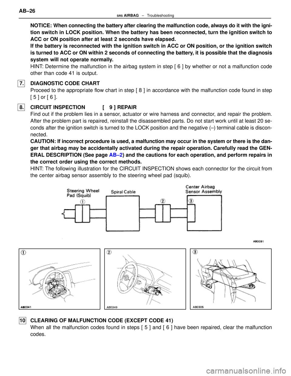
HINT: The following illustration for the CIRCUIT INSPECTION shows each conne\
ctor for the circuit from
the center airbag sensor assembly to the steering wheel pad (squib).
10 CLEARING OF MALFUNCTION CODE (EXCEPT CODE 41) When all the malfunction codes found in steps [ 5 ] and [ 6 ] have been repa\
ired, clear the malfunction
codes.
AB±26
SRS AIRBAG
± Troubleshooting
WhereEverybodyKnowsYourName
Page 245 of 4087
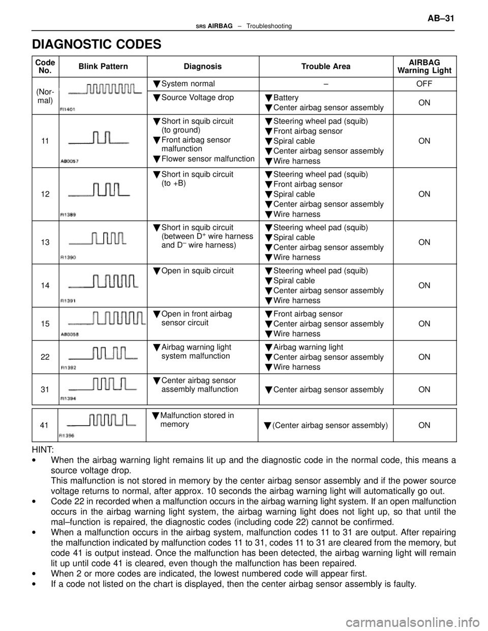
DIAGNOSTIC CODES
CodeNo.Blink PatternDiagnosisTrouble AreaAIRBAG
Warning Light
(Nor
� System normal±OFF
(Nor-
mal)� Source Voltage drop�Battery
� Center airbag sensor assemblyON
11
�Short in squib circuit
(to ground)
� Front airbag sensor
malfunction
� Flower sensor malfunction�Steering wheel pad (squib)
� Front airbag sensor
� Spiral cable
� Center airbag sensor assembly
� Wire harness
ON
12
�Short in squib circuit
(to +B)�Steering wheel pad (squib)
� Front airbag sensor
� Spiral cable
� Center airbag sensor assembly
� Wire harness
ON
13
�Short in squib circuit
(between D+ wire harness
and D± wire harness)
� Steering wheel pad (squib)
� Spiral cable
� Center airbag sensor assembly
� Wire harness
ON
14
�Open in squib circuit�Steering wheel pad (squib)
� Spiral cable
� Center airbag sensor assembly
� Wire harness
ON
15
�Open in front airbag
sensor circuit�Front airbag sensor
� Center airbag sensor assembly
� Wire harness
ON
22
�Airbag warning light
system malfunction�Airbag warning light
� Center airbag sensor assembly
� Wire harness
ON
31
�Center airbag sensor
assembly malfunction
�Center airbag sensor assemblyON
41
�Malfunction stored in
memory
�(Center airbag sensor assembly)ON
HINT:
w When the airbag warning light remains lit up and the diagnostic code in the n\
ormal code, this means a
source voltage drop.
This malfunction is not stored in memory by the center airbag sensor ass\
embly and if the power source
voltage returns to normal, after approx. 10 seconds the airbag warning l\
ight will automatically go out.
w Code 22 in recorded when a malfunction occurs in the airbag warning light sy\
stem. If an open malfunction
occurs in the airbag warning light system, the airbag warning light does not l\
ight up, so that until the
mal±function is repaired, the diagnostic codes (including code 22) cannot be confi\
rmed.
w When a malfunction occurs in the airbag system, malfunction codes 11 to 31 are output. After repairing
the malfunction indicated by malfunction codes 11 to 31, codes 11 to 31 are cleared from the memory, but
code 41 is output instead. Once the malfunction has been detected, the airba\
g warning light will remain
lit up until code 41 is cleared, even though the malfunction has been re\
paired.
w When 2 or more codes are indicated, the lowest numbered code will appear\
first.
w If a code not listed on the chart is displayed, then the center airbag s\
ensor assembly is faulty. AB±31
SRS AIRBAG
± Troubleshooting
WhereEverybodyKnowsYourName
Page 256 of 4087
Diag. Code 11Short is Squib Circuit or Front Airbag
Sensor Circuit (to Ground)
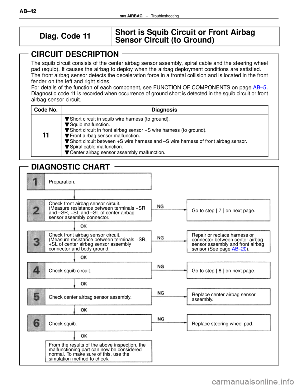
CIRCUIT DESCRIPTION
The squib circuit consists of the center airbag sensor assembly, spiral cable and the steering wheel
pad (squib). It causes the airbag to deploy when the airbag deployment\
conditions are satisfied.
The front airbag sensor detects the deceleration force in a frontal collision and is located in \
the front
fender on the left and right sides.
For details of the function of each component, see FUNCTION OF COMPONENTS on page AB±5.
Diagnostic code 11 is recorded when occurrence of ground short is detected in the squib circui\
t or front
airbag sensor circuit.
Code No.
Diagnosis
11
� Short circuit in squib wire harness (to ground).
� Squib malfunction.
� Short circuit in front airbag sensor +S wire harness (to ground).
� Front airbag sensor malfunction.
� Short circuit between +S wire harness and ±S wire harness of front ai\
rbag sensor.
� Spiral cable malfunction.
� Center airbag sensor assembly malfunction.
DIAGNOSTIC CHART
Preparation.
Check front airbag sensor circuit.
(Measure resistance between terminals +SR
and ±SR, +SL and ±SL of center airbag
sensor assembly connector.
Check front airbag sensor circuit.
(Measure resistance between terminals +SR,
+SL of center airbag sensor assembly
connector and body ground.
Check squib circuit.
Check center airbag sensor assembly.
Check squib.
From the results of the above inspection, the
malfunctioning part can now be considered
normal. To make sure of this, use the
simulation method to check. Go to step [ 7 ] on next page.
Repair or replace harness or
connector between center airbag
sensor assembly and front airbag
sensor (See page
AB±20).
Go to step [ 8 ] on next page.
Replace center airbag sensor
assembly.
Replace steering wheel pad.
AB±42SRS AIRBAG ± Troubleshooting
WhereEverybodyKnowsYourName
Page 258 of 4087
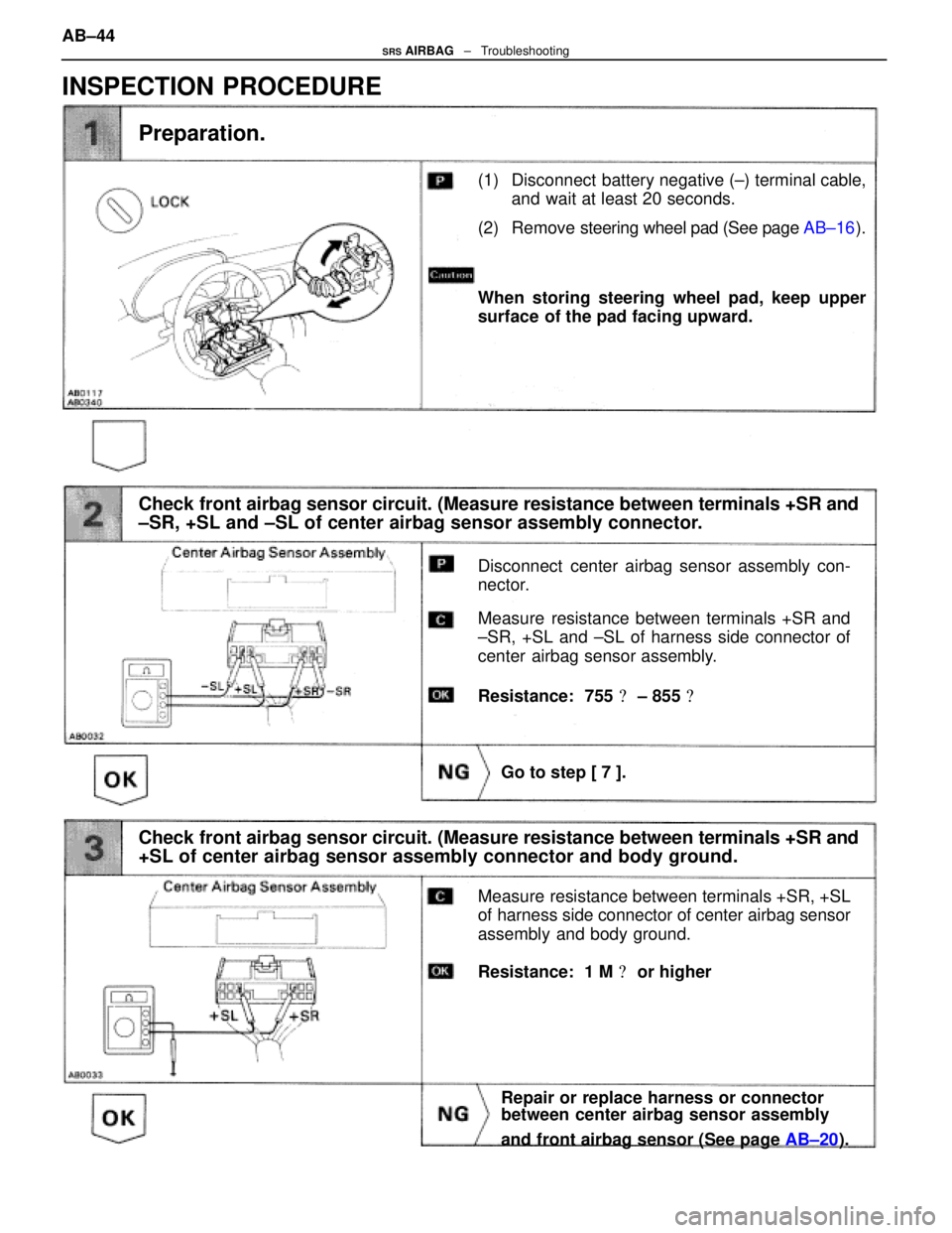
(1) Disconnect battery negative (±) terminal cable,and wait at least 20 seconds.
(2) Remove steering wheel pad (See page AB±16).
Check front airbag sensor circuit. (Measure resistance between terminals +SR\
and
±SR, +SL and ±SL of center airbag sensor assembly connector.
Preparation.
Disconnect center airbag sensor assembly con-
nector.
Measure resistance between terminals +SR and
±SR, +SL and ±SL of harness side connector of
center airbag sensor assembly.
Go to step [ 7 ].
When storing steering wheel pad, keep upper
surface of the pad facing upward.
Resistance: 755 � ± 855 �
Check front airbag sensor circuit. (Measure resistance between terminals +SR\
and
+SL of center airbag sensor assembly connector and body ground.
Measure resistance between terminals +SR, +SL
of harness side connector of center airbag sensor
assembly and body ground.
Repair or replace harness or connector
between center airbag sensor assembly
and front airbag sensor (See page AB±20).
Resistance: 1 M � or higher
INSPECTION PROCEDURE
AB±44SRS AIRBAG ± Troubleshooting
WhereEverybodyKnowsYourName
Page 259 of 4087
(1) Connect connector to center airbag sensorassembly.
(2) Using a service wire, connect D
+, D± on spiral
cable side of connector between spiral cable
and steering wheel pad.
(3) Connect negative (±) terminal cable to battery, and wait at least 2 seconds.
Check squib circuit.
Codes other than code 11 may be output at this
time, but this is not relevant.
Measure resistance between D+, D± on spiral cable
side of connector between spiral cable and steer-
ing wheel pad and body ground.
Go to step [ 8 ].
Diagnostic code 11 is not output.
Resistance: 1 M � or higher
Replace center airbag sensor assembly.
Check center airbag sensor assembly.
(1) Turn ignition switch ACC or ON and wait at
least 20 seconds.
(2) Using SST, connect terminals Tc and E
1 of
TDCL.
SST 09843±18020
(3) Check diagnostic code. AB±45
SRS AIRBAG
± Troubleshooting
WhereEverybodyKnowsYourName
Page 260 of 4087
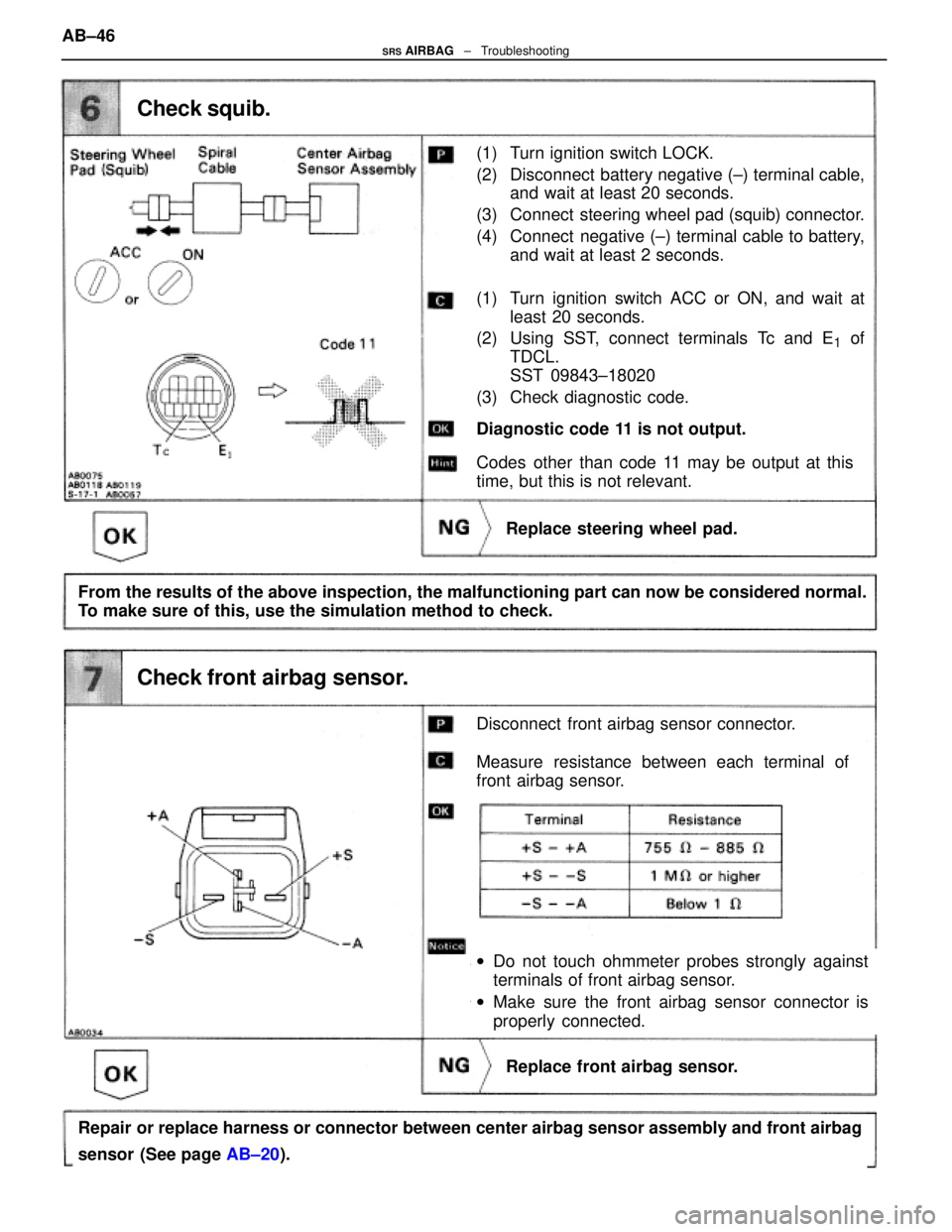
(1) Turn ignition switch LOCK.
(2) Disconnect battery negative (±) terminal cable,and wait at least 20 seconds.
(3) Connect steering wheel pad (squib) connector.
(4) Connect negative (±) terminal cable to battery, and wait at least 2 seconds.
Check squib.
Disconnect front airbag sensor connector.
Measure resistance between each terminal of
front airbag sensor.
Replace front airbag sensor.
Diagnostic code 11 is not output.
Replace steering wheel pad.
wDo not touch ohmmeter probes strongly against
terminals of front airbag sensor.
w Make sure the front airbag sensor connector is
properly connected.
From the results of the above inspection, the malfunctioning part can now be\
considered normal.
To make sure of this, use the simulation method to check.
Repair or replace harness or connector between center airbag sensor assembly a\
nd front airbag
sensor (See page AB±20).
Check front airbag sensor.
(1) Turn ignition switch ACC or ON, and wait at
least 20 seconds.
(2) Using SST, connect terminals Tc and E
1 of
TDCL.
SST 09843±18020
(3) Check diagnostic code.
Codes other than code 11 may be output at this
time, but this is not relevant.
AB±46
SRS AIRBAG
± Troubleshooting
WhereEverybodyKnowsYourName
Page 261 of 4087
Check squib circuit.
Disconnect connector between center airbag sen-
sor assembly and spiral cable.
Measure resistance between D+, D± on spiral
cable side of connector between spiral cable and
steering wheel pad and body ground.
Repair or replace spiral cable.
Repair or replace harness or connector between
center airbag sensor assembly and spiral cable,
Resistance: 1 M � or higher AB±47
SRS AIRBAG
± Troubleshooting
WhereEverybodyKnowsYourName