1991 FORD FESTIVA ignition control module
[x] Cancel search: ignition control modulePage 5 of 454

TURBO BOOST GAUGE & SENSOR (CAPRI)
1. Disconnect 3-pin boost sensor electrical connected located on right side of firewall. Turn ignition on. Measure voltage between
Yellow/Green and Black wires. Voltage should be greater than 10 volts. Turn ignition off. If voltage is greater than 10 volts, go t o n e xt
step. If voltage is 10 volts or less, repair Yellow/Green or Black wires as necessary.
2. Remove instrument panel. See INSTRUMENT PANEL
under REMOVAL & INSTALLATION. Disconnect instrument panel 8-pin
connector. With boost sensor disconnected, measure resistance through White/Black between instrument panel and boost sensor harness
connector. If resistance is less than 5 ohms, go to next step. If resistance is 5 ohms or more, repair or replace White/Black wire.
3. With 8-pin instrument panel connector disconnected, ground White/Black at boost gauge. Boost gauge should read low. Apply 12 vo l t s
to White/Black wire at boost gauge. Boost gauge should read high. If boost gauge operates as specified, go to next step. If boost gauge
does not operate as specified, replace boost gauge.
4. Reconnect instrument panel connectors (if removed). With ignition on and boost sensor disconnected, install jumper wire between
Yellow/Green and White/Black wires of boost sensor vehicle harness connector. Boost gauge should read high. If boost gauge reads
high, replace boost sensor. If boost gauge does not read high, go to TROUBLE SHOOTING
for other possible causes.
REMOVAL & INSTALLATION
INSTRUMENT PANEL
Removal & Installation (Capri)
1. Disconnect negative battery cable. Pull storage compartment from heater/radio bezel. Pull outward and remove trim covers located on
both sides of steering column. Remove retaining screws and carefully pull instrument panel bezel partially away from dash. Disconnect
electrical connectors from clock and switches in bezel. Remove instrument panel bezel.
2. Disconnect speedometer cable from transaxle. Remove instrument panel retaining screws and slide instrument panel outward. Press lock
tab and release speedometer cable from instrument panel. Remove electrical connectors from rear of instrument panel. Remove
instrument panel. To install instrument panel, reverse removal procedure.
Removal & Installation (Festiva)
1. Disconnect negative battery cable. Remove upper and lower steering column covers. Remove screws from panel bezel and remove bezel.
Disconnect rear wiper switch and rear defogger switch wiring harness connectors (if equipped).
2. Remove instrument panel-to-dash screws. Pull panel from dash. Reach behind panel and release speedometer drive cable lock tab. Lift
lock tabs and disconnect 2 electrical connectors from rear of panel. Remove panel. To install instrument panel, reverse removal
procedure.
INDICATOR LIGHTS
Removal & Installation
Remove instrument panel for access to indicator light bulbs. See INSTRUMENT PANEL under REMOVAL & INSTALLATION. To remove
bulb, rotate bulb counterclockwise to disengage locking tabs. When tabs release, pull bulb from printed circuit board. To install bulb, reverse
removal procedure. Install instrument panel and test lights.
SPEEDOMETER R & I
Removal & Installation (Capri)
R e mo ve n e ga t ive b a t t e r y c a b l e . R e mo ve in st r u me n t p a n e l . S e e INSTRUMENT PANEL under REMOVAL & INSTALLATION. Disassemble
instrument panel and remove speedometer/tachometer/boost gauge assembly from instrument panel. To install, apply a 3/16" (4.6 mm) b al l o f
Silicone Damping Grease (D7AZ-19A331-A) into drive hole of speedometer head. Reverse removal procedure to complete installation.
Removal & Installation (Festiva)
R e mo ve n e ga t ive b a t t e r y c a b l e . R e mo ve in st r u me n t p a n e l . S e e INSTRUMENT PANEL under REMOVAL & INSTALLATION. Disassemble
instrument panel and remove speedometer head assembly from instrument panel. Speedometer is a separate module and can be removed
independently from gauges. To install, reverse removal procedure.
SPEED SENSOR
On vehicles equipped with speed control, a speed sensor is mounted in speedometer head assembly. If replacement is necessary, speedometer
head assembly must be replaced. See SPEEDOMETER R & I
under REMOVAL & INSTALLATION.
FUEL GAUGE
Removal & Installation
Remo ve in st ru men t p an el . See INSTRUMENT PANEL under REMOVAL & INSTALLATION. Disassemble panel and remove fuel gauge.
To install gauge, reverse removal procedure. On Capri, the fuel/volt gauge must be replaced as an assembly.
FUEL SENDING UNIT
Removal & Installation
1. For Festiva, remove rear seat. For Capri, remove rear seat cushion. On Festiva, remove carpet hold-down pins and lift carpet for access
to sending unit access plate. On all models, remove access plate screws. NOTE:Federal law requires that a label stating the odom eter has been repaired or replaced be affixed to any
vehicle that has its odom eter repaired, replaced or set to zero.
Page 4 of 5 MITCHELL 1 ARTICLE - INSTRUMENT PANEL 1991 ACCESSORIES & SAFETY EQUIPMENT Ford Motor Co. Switches
...
3/10/2009 http://www.eautorepair.net/app/PrintItems.asp?S0=2097152&S1=0&SG=%7B959286D2%2D3A85%2D4BFC%2D9C5C%2D
...
Page 20 of 454
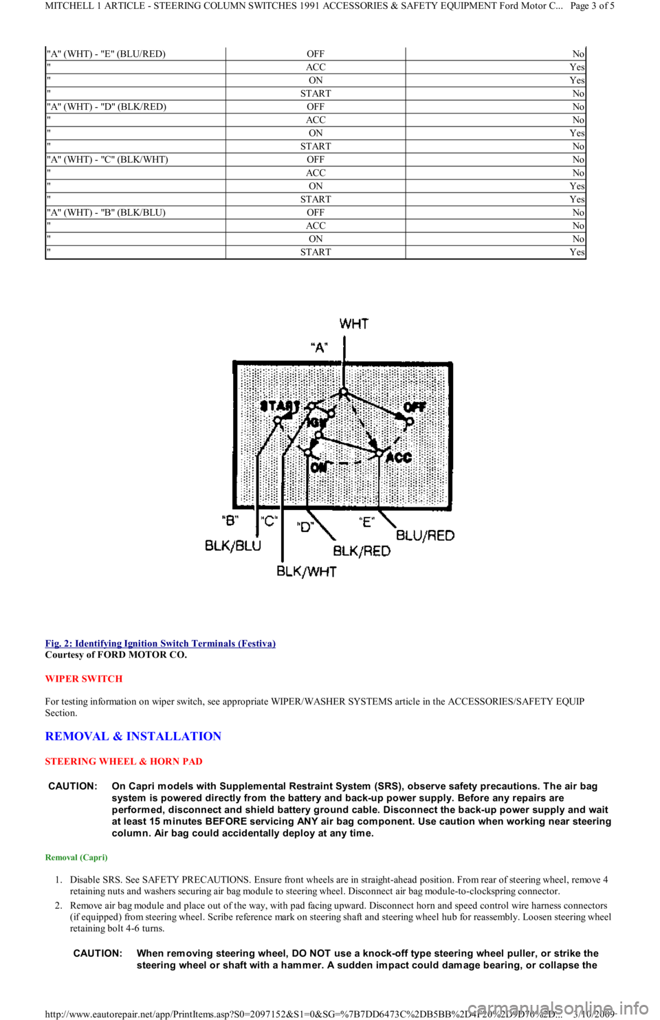
Fig. 2: Identifying Ignition Switch Terminals (Festiva)
Courtesy of FORD MOTOR CO.
WIPER SWITCH
For testing information on wiper switch, see appropriate WIPER/WASHER SYSTEMS article in the ACCESSORIES/SAFETY EQUIP
Section.
REMOVAL & INSTALLATION
STEERING WHEEL & HORN PAD
Removal (Capri)
1. Disable SRS. See SAFETY PRECAUTIONS. Ensure front wheels are in straight-ahead position. From rear of steering wheel, remove 4
retaining nuts and washers securing air bag module to steering wheel. Disconnect air bag module-to-clockspring connector.
2. Remove air bag module and place out of the way, with pad facing upward. Disconnect horn and speed control wire harness connectors
(if equipped) from steering wheel. Scribe reference mark on steering shaft and steering wheel hub for reassembly. Loosen steering wheel
retaining bolt 4-6 turns.
"A" (WHT) - "E" (BLU/RED)OFFNo
"ACCYes
"ONYes
"STARTNo
"A" (WHT) - "D" (BLK/RED)OFFNo
"ACCNo
"ONYes
"STARTNo
"A" (WHT) - "C" (BLK/WHT)OFFNo
"ACCNo
"ONYes
"STARTYes
"A" (WHT) - "B" (BLK/BLU)OFFNo
"ACCNo
"ONNo
"STARTYes
CAUTION: On Capri m odels with Supplem ental Restraint System (SRS), observe safety precautions. T he air bag
system is powered directly from the battery and back-up power supply. Before any repairs are
perform ed, disconnect and shield battery ground cable. Disconnect the back-up power supply and wait
at least 15 m inutes BEFORE servicing ANY air bag com ponent. Use caution when working near steering
colum n. Air bag could accidentally deploy at any tim e.
CAUT ION: When rem oving steering wheel, DO NOT use a knock-off type steering wheel puller, or strike the
steering wheel or shaft with a ham m er. A sudden im pact could dam age bearing, or collapse the
Page 3 of 5 MITCHELL 1 ARTICLE - STEERING COLUMN SWITCHES 1991 ACCESSORIES & SAFETY EQUIPMENT Ford Motor C
...
3/10/2009 http://www.eautorepair.net/app/PrintItems.asp?S0=2097152&S1=0&SG=%7B7DD6473C%2DB5BB%2D4F20%2D9D70%2D
...
Page 21 of 454
3. Position Steering Wheel Remover (T67L-3600-A) on steering wheel. Tighten bolt on remover until steering wheel is loose. Remove
steering wheel puller, steering wheel retaining bolt, and steering wheel.
Installation
1. Ensure front wheels are in straight-ahead position. Route clockspring wiring harness through steering wheel opening. Position steering
wheel on steering shaft and align reference marks.
2. Ensure clockspring wire is not pinched when positioning steering wheel. Install new steering wheel retaining bolt and tighten to
specification. See TORQUE SPECIFICATIONS table at end of article. Connect horn and speed control wiring connectors (if equipped)
to steering wheel.
3. Connect air bag module-to-clockspring connector. Install air bag module. Tighten air bag module retaining nuts to specification.
Activate SRS. See SAFETY PRECAUTIONS. Check AIR BAG light to ensure system is functioning properly.
Removal (Festiva)
From back of steering wheel, remove 2 screws securing horn pad. Disconnect horn wire from horn pad and remove pad. Remove steering
wheel nut. Scribe reference mark on steering shaft and steering wheel hub for reassembly. Using Steering Wheel Puller (T67L-3600-A),
remove steering wheel.
Installation
Position steering wheel on steering shaft and align reference marks. Be sure cutouts in rear cover engage turn signal canceling cam. To
complete installation, reverse removal procedure.
COMBINATION SW ITCH
Removal (Capri)
1. Disconnect negative battery cable. Remove lower steering column cover. Remove center access panel and trim cover under steering
column. Remove left side defroster connector tube. Remove steering column upper retaining bolts. Column will pivot downward and
rest on instrument panel brace.
2. Remove 2 switch retaining screws and remove switch. Grasp switch and lever and pull lever out of switch. Disconnect switch electrical
connectors and remove switch.
Installation
Align key with slot and install lever in switch assembly. Position switch on steering column and install retaining screws. To complete
installation, reverse removal procedure.
Removal (Festiva)
1. Disconnect negative battery cable. Remove steering wheel. See STEERING WHEEL & HORN PAD under REMOVAL &
INSTALLATION. Remove 4 screws from upper half of lower steering column cover and remove cover. Remove upper steering column
cover. Remove 5 clips from lower half of lower steering column cover and remove cover.
2. Release wiring harness clip and unplug 4 harness connectors from back of combination switch. From below steering column, loosen
band clamp securing switch hub to steering column jacket. Pull switch assembly from steering column.
Installation
Slide combination switch assembly onto steering column. Make sure switch assembly is seated and level against end of column jacket. To
complete installation, reverse removal procedure.
HEADLIGHT SWITCH
Removal & Installation (Capri)
1. Headlight off/on switch is located on left side of instrument panel bezel. Disconnect negative battery cable. Pull out center storage
compartment. Remove 2 upper screws, 2 lower screws and heater/radio bezel. Pull outward and remove trim covers located on both
sides of steering column.
2. Remove retaining screws and carefully pull instrument panel bezel partially away from dash. Disconnect electrical connector from
headlight switch. Depress tangs on both sides of switch and remove switch from bezel. To install, reverse removal procedure.
IGNITION SWITCH & LOCK CYLINDER
Removal (Capri)
1. Disconnect negative battery cable. Remove lower steering column cover. Remove center access panel and trim cover under steering
column. Remove left side defroster connector tube. Remove steering column upper retaining bolts. Column will pivot downward and
rest on instrument panel brace. steering colum n.
CAUT ION: Rem ove steering wheel carefully to avoid dam aging clockspring wiring, air bag m odule connector, or
accidentally turning clockspring. After steering wheel rem oval, tape clockspring in position to prevent
dam age and keep it from being turned accidentally.
CAUTION: Ensure that no wiring is pinched beneath steering colum n when lowered.
Page 4 of 5 MITCHELL 1 ARTICLE - STEERING COLUMN SWITCHES 1991 ACCESSORIES & SAFETY EQUIPMENT Ford Motor C
...
3/10/2009 http://www.eautorepair.net/app/PrintItems.asp?S0=2097152&S1=0&SG=%7B7DD6473C%2DB5BB%2D4F20%2D9D70%2D
...
Page 47 of 454
SOLENOIDS & SOLENOID VALVES
SOLENOIDS & SOLENOID VALVES LOCATION
SWITCHES
SWITCHES LOCATION
MISCELLANEOUS
MISCELLANEOUS LOCATION
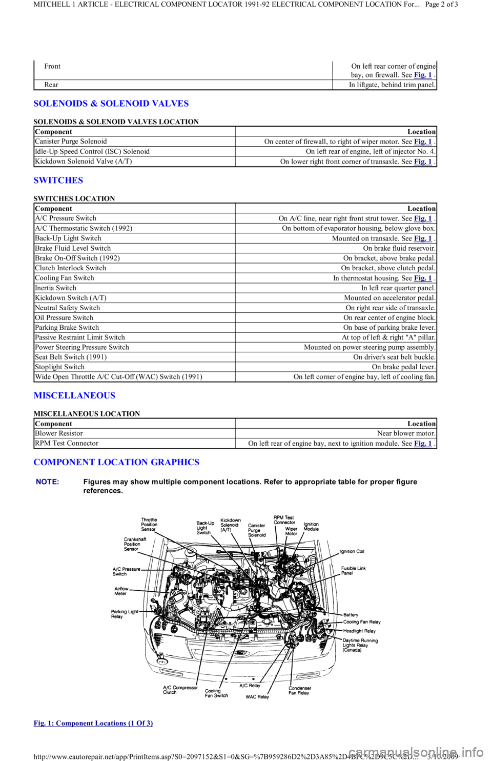
COMPONENT LOCATION GRAPHICS
Fig. 1: Component Locations (1 Of 3)
FrontOn left rear corner of engine
bay, on firewall. See Fig. 1
.
RearIn liftgate, behind trim panel.
ComponentLocation
Canister Purge SolenoidOn center of firewall, to right of wiper motor. See Fig. 1 .
Idle-Up Speed Control (ISC) SolenoidOn left rear of engine, left of injector No. 4.
Kickdown Solenoid Valve (A/T)On lower right front corner of transaxle. See Fig. 1 .
ComponentLocation
A/C Pressure SwitchOn A/C line, near right front strut tower. See Fig. 1 .
A/C Thermostatic Switch (1992)On bottom of evaporator housing, below glove box.
Back-Up Light SwitchMounted on transaxle. See Fig. 1 .
Brake Fluid Level SwitchOn brake fluid reservoir.
Brake On-Off Switch (1992)On bracket, above brake pedal.
Clutch Interlock SwitchOn bracket, above clutch pedal.
Cooling Fan SwitchIn thermostat housing. See Fig. 1 .
Inertia SwitchIn left rear quarter panel.
Kickdown Switch (A/T)Mounted on accelerator pedal.
Neutral Safety SwitchOn right rear side of transaxle.
Oil Pressure SwitchOn rear center of engine block.
Parking Brake SwitchOn base of parking brake lever.
Passive Restraint Limit SwitchAt top of left & right "A" pillar.
Power Steering Pressure SwitchMounted on power steering pump assembly.
Seat Belt Switch (1991)On driver's seat belt buckle.
Stoplight SwitchOn brake pedal lever.
Wide Open Throttle A/C Cut-Off (WAC) Switch (1991)On left corner of engine bay, left of cooling fan.
ComponentLocation
Blower ResistorNear blower motor.
RPM Test ConnectorOn left rear of engine bay, next to ignition module. See Fig. 1 .
NOTE:Figures m ay show m ultiple com ponent locations. Refer to appropriate table for proper figure
references.
Page 2 of 3 MITCHELL 1 ARTICLE - ELECTRICAL COMPONENT LOCATOR 1991-92 ELECTRICAL COMPONENT LOCATION For...
3/10/2009 http://www.eautorepair.net/app/PrintItems.asp?S0=2097152&S1=0&SG=%7B959286D2%2D3A85%2D4BFC%2D9C5C%2D
...
Page 65 of 454

Fig. 2: Ground Numbers & Locations (2001 & Prior Model Years)
WIRING DIAGRAM COMPONENT LOCATIONS
When trying to locate a component in a wiring diagram and you don't know the specific system where it is located, use this handy component
locator to find the system wiring diagram in which the component is located. Then, go to that system and locate the component within the
wiring diagram.
For example, if you don't know the specific system in which the ignition switch is located, look up ignition switch in the wiring diagram
component location tables and go to the appropriate wiring diagram(s) which contain either full or partial views of the ignition switch. The full
view of the ignition switch is located in Power Distribution.
The first listing for the component will be the full or most complete view of the component. Additional listings will be partial views of the
component. Not all components are used on all models.
All components will have a partial view in Ground Distribution and Power Distribution. Data Link Connectors show connecting circuits
between modules. Alternate names for components may be listed in wiring diagram component locations tables.
WIRING DIAGRAM COMPONENT LOCATIONS
ComponentWiring Diagram
ABS Electronic Control UnitAnti-Lock Brakes; Data Link Connectors
ABS Hydraulic UnitAnti-Lock Brakes
Acceleration SensorAnti-Lock Brakes
Accessory Delay RelayPower Windows
A/C Compressor Clutch RelayEngine Performance
A/C SensorEngine Performance
A/C Pressure SwitchEngine Performance
Adaptive Lamp Control ModuleExterior Lights
Air Bag(s)Air Bag Restraint System
Air Bag ModuleAir Bag Restraint System
Air Bag Sensor(s)Air Bag Restraint System
Air Injection Pump RelayEngine Performance
Air Temperature SensorOverhead Console
Alternator (Generator)Generators & Regulators
Anti-Theft Control ModuleAnti-Theft System; Starters
Page 3 of 6 MITCHELL 1 ARTICLE - GENERAL INFORMATION Using Mitchell1's Wiring Diagrams
3/10/2009 http://www.eautorepair.net/app/PrintItems.asp?S0=2097152&S1=0&SG=%7B959286D2%2D3A85%2D4BFC%2D9C5C%2D
...
Page 67 of 454

Height SensorElectronic Suspension
HornsSteering Column Switches
Horn RelaySteering Column Switches
Idle Air Control (IAC) Motor/ValveEngine Performance
Ignition Coil(s)Engine Performance
Ignition Key Lock CylinderAnti-Theft System
Ignition ModuleEngine Performance
Ignition SwitchPower Distribution; Engine Performance; Generators &
Regulators; Starters
Illuminated Entry ModuleIllumination/Interior Lights
Illumination LightsIllumination/Interior Lights
Impact SensorAir Bag Restraint System
Inertia Fuel Shutoff SwitchEngine Performance
In h ib it Rel ayStarters
Instrument ClusterAnalog Instrument Panels
Intake Air Temperature (IAT) SensorEngine Performance
Interior LightsIllumination/Interior Lights
In t erl o ck Swit chStarters
Junction BlockPower Distribution
Keyless Entry ReceiverRemote Keyless Entry
Key Reminder SwitchStarters
Knock SensorEngine Performance
Lamp Control ModuleExterior Lights
License Plate LampExterior Lights
Lighting Control ModuleLighting Control Modules; Anti-Theft System; Daytime Running
Lights; Headlight Systems
Lower RelayPower Convertible Top
Malfunction Indicator Light (MIL)Engine Performance; Instrument Panels
Manifold Absolute Pressure (MAP) SensorEngine Performance
Mass Airflow (MAF) SensorEngine Performance
Mega FuseGenerators & Regulators
Memory Seat/Mirror ModuleMemory Systems
M ir r o r De fo gge rRear Window Defogger
Moon Roof MotorPower Moon Roof
Moon Roof RelayPower Moon Roof
Multi-Function Control ModuleWarning Systems
Neutral Safety SwitchStarters
Oil Level SwitchEngine Performance
Oil Pressure Switch/Sending UnitAnalog Instrument Panels; Engine Performance
Overhead ConsoleOverhead Console
Oxygen Sensor(s) (O2S)Engine Performance
Parking Brake SwitchAnalog Instrument Panels
Park LightsExterior Lights
Park/Neutral Position SwitchStarters; Engine Performance; Anti-Theft System; Body Control
Module
Perimeter Lighting Control RelayExterior Lights
Power AmplifierPower Antennas
Power Antenna ModulePower Antennas
Power Antenna MotorPower Antennas
Power Distribution CenterPower Distribution; Generators & Regulators; Starters
Power Door Lock MotorsPower Door Locks
Power Mirror MotorsPower Mirrors; Memory Systems
Power Sliding Door ControllerPower Sliding Side Door
Power Seat MotorsPower Seats; Memory Systems
Power Steering Pressure SwitchEngine Performance
Power Top MotorPower Convertible Top
Power Top Relay(s)Power Convertible Top
Powertrain Control ModuleEngine Performance; Analog Instrument Panels; Cruise Control
Systems; Data Link Connectors; Generators & Regulators; Starters
Power Window MotorsPower Windows
Power Window Relay(s)Power Windows
Radiator Fan Motor(s)Electric Cooling Fans
Radiator Fan Relay(s)Engine Performance; Electric Cooling Fans;
Rainsense ModuleWiper/Washer Systems
Raise RelayPower Convertible Top
Remote Anti-Theft Personality (RAP) ModuleAnti-Theft System; Starters; Warning Systems
Seat Belt PretensionersAir Bag Restraint System
Seat Belt Retractor SolenoidPassive Restraints
Seat Belt SwitchAir Bag Restraint System; Passive Restraints
Shift Interlock SolenoidShift Interlock Systems
Page 5 of 6 MITCHELL 1 ARTICLE - GENERAL INFORMATION Using Mitchell1's Wiring Diagrams
3/10/2009 http://www.eautorepair.net/app/PrintItems.asp?S0=2097152&S1=0&SG=%7B959286D2%2D3A85%2D4BFC%2D9C5C%2D
...
Page 69 of 454
Back To Article
WIRING DIAGRAMS
1991 WIRING DIAGRAMS Ford Motor Co.
IDENTIFICATION
COMPONENT LOCATION MENU
COMPONENT LOCATIONS
WIRING DIAGRAMS
ComponentFigure No. (Location)
A/C RELAY3 (B 8)
A/T SELECT LIGHT3 (E 8)
ALTERNATOR1 (C 3)
BACK-UP LIGHT SWITCH5 (D 19)
BATTERY1 (A 2)
BLOWER SWITCH3 (C 9)
BRAKE WARNING SWITCH1 (C 2)
CIG LTR4 (E 14)
CLUTCH INTERLOCK SWITCH (M/T)1 (B 2)
CONDENSER FAN (A/T)3 (C 8)
COOLANT FAN MOTOR1 (D 3)
COOLANT FAN RELAY1 (D 3)
DEFOG SWITCH5 (C 16)
DIR/HAZARD SWITCH4 (B-C 12)
ELECT CONTROL ASSY (ECA)2 (A 4-7)
FRONT WASHER MOTOR1 (E 3)
FRONT WIPER MOTOR1 (E 3)
FRONT WIPER/WASHER SWITCH5 (A 16)
FUEL PUMP INERTIA SWITCH2 (D 4)
FUEL PUMP RELAY2 (C 4)
FUSE BLOCK3 (D-E 9-10)
HEADLIGHT RELAY4 (D 14)
HORN RELAY3 (E 11)
HORN SWITCH4 (E 15)
IGNITION COIL2 (E 5)
IGNITION KEY REMINDER SWITCH4 (E 13)
IGNITION SWITCH3 (C-D 11)
INSTRUMENT CLUSTER4 (A-E 15)
INSTRUMENT PANEL LIGHT CONTROL4 (D-E 12)
INTERIOR LIGHT SWITCH4 (E 14)
LIGHT SWITCH4 (C-D 12)
MAIN FUSE PANEL1 (A 3)
MAIN RELAY2 (D 5)
NEUTRAL SAFETY SWITCH (A/T)1 (B 2)
PARKING LIGHT RELAY4 (C 14)
PASSIVE RESTRAINT CONTROL MODULE3 (A 11)
REAR WASHER MOTOR5 (D 17)
REAR WIPER/WASHER SWITCH5 (E 16)
SHIFT LOCK SERVO ASSY4 (A 12)
STARTER1 (B 3)
STOP LIGHT SWITCH5 (D 19)
TIMER/BUZZER UNIT4 (E 12)
TRUNK LIGHT5 (B 16)
WAC RELAY3 (B 8)
Page 1 of 6 MITCHELL 1 ARTICLE - WIRING DIAGRAMS 1991 WIRING DIAGRAMS Ford Motor Co.
3/10/2009 http://www.eautorepair.net/app/PrintItems.asp?S0=2097152&S1=0&SG=%7B959286D2%2D3A85%2D4BFC%2D9C5C%2D
...
Page 164 of 454
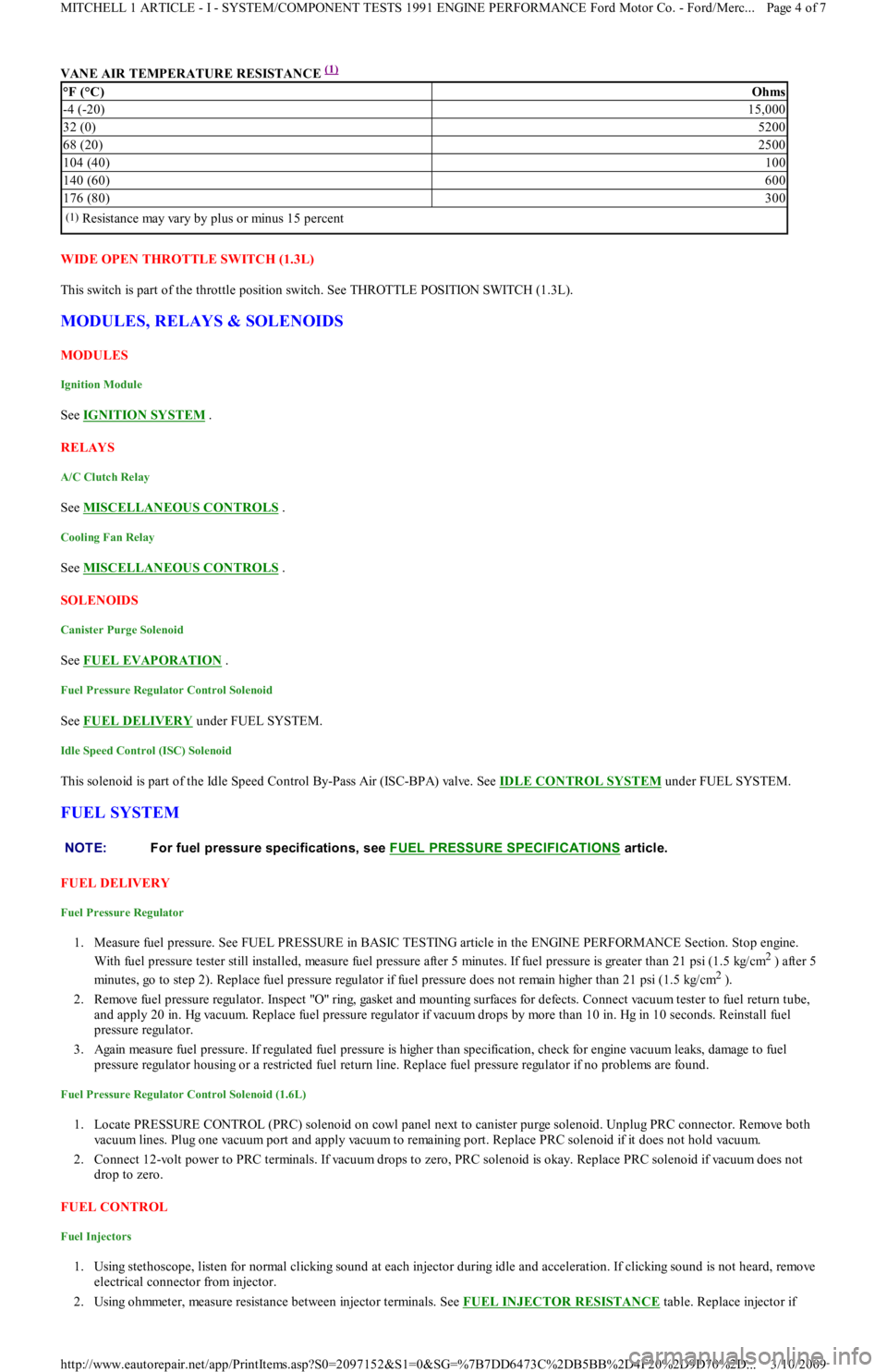
VANE AIR TEMPERATURE RESISTANCE (1)
WIDE OPEN THROTTLE SWITCH (1.3L)
This switch is part of the throttle position switch. See THROTTLE POSITION SWITCH (1.3L).
MODULES, RELAYS & SOLENOIDS
MODULES
Ignition Module
See IGNITION SYSTEM .
RELAYS
A/C Clutch Relay
See MISCELLANEOUS CONTROLS .
Cooling Fan Relay
See MISCELLANEOUS CONTROLS .
SOLENOIDS
Canister Purge Solenoid
See FUEL EVAPORATION .
Fuel Pressure Regulator Control Solenoid
See FUEL DELIVERY under FUEL SYSTEM.
Idle Speed Control (ISC) Solenoid
This solenoid is part of the Idle Speed Control By-Pass Air (ISC-BPA) valve. See IDLE CONTROL SYSTEM under FUEL SYSTEM.
FUEL SYSTEM
FUEL DELIVERY
Fuel Pressure Regulator
1. Measure fuel pressure. See FUEL PRESSURE in BASIC TESTING article in the ENGINE PERFORMANCE Section. Stop engine.
With fuel pressure tester still installed, measure fuel pressure after 5 minutes. If fuel pressure is greater than 21 psi (1.5 kg/cm
2 ) after 5
minutes, go to step 2). Replace fuel pressure regulator if fuel pressure does not remain higher than 21 psi (1.5 kg/cm
2 ).
2. Remove fuel pressure regulator. Inspect "O" ring, gasket and mounting surfaces for defects. Connect vacuum tester to fuel return tube,
and apply 20 in. Hg vacuum. Replace fuel pressure regulator if vacuum drops by more than 10 in. Hg in 10 seconds. Reinstall fuel
pressure regulator.
3. Again measure fuel pressure. If regulated fuel pressure is higher than specification, check for engine vacuum leaks, damage to fuel
pressure regulator housing or a restricted fuel return line. Replace fuel pressure regulator if no problems are found.
Fuel Pressure Regulator Control Solenoid (1.6L)
1. Locate PRESSURE CONTROL (PRC) solenoid on cowl panel next to canister purge solenoid. Unplug PRC connector. Remove both
vacuum lines. Plug one vacuum port and apply vacuum to remaining port. Replace PRC solenoid if it does not hold vacuum.
2. Connect 12-volt power to PRC terminals. If vacuum drops to zero, PRC solenoid is okay. Replace PRC solenoid if vacuum does not
drop to zero.
FUEL CONTROL
Fuel Injectors
1. Using stethoscope, listen for normal clicking sound at each injector during idle and acceleration. If clicking sound is not heard, remove
electrical connector from injector.
2. Using ohmmeter, measure resistance between injector terminals. See FUEL INJECTOR RESISTANCE
table. Replace injector if
°F (°C)Ohms
-4 (-20)15,000
32 (0)5200
68 (20)2500
104 (40)100
140 (60)600
176 (80)300
(1)Resistance may vary by plus or minus 15 percent
NOTE:For fuel pressure specifications, see FUEL PRESSURE SPECIFICAT IONS
article.
Page 4 of 7 MITCHELL 1 ARTICLE - I - SYSTEM/COMPONENT TESTS 1991 ENGINE PERFORMANCE Ford Motor Co. - Ford/Merc
...
3/10/2009 http://www.eautorepair.net/app/PrintItems.asp?S0=2097152&S1=0&SG=%7B7DD6473C%2DB5BB%2D4F20%2D9D70%2D
...