1991 FORD FESTIVA fig 9
[x] Cancel search: fig 9Page 7 of 454
Back To Article
DEFOGGER - REAR WINDOW
1991 ACCESSORIES & SAFET Y EQUIPMENT Rear Window Defoggers - Rear Window
DESCRIPTION & OPERATION
The rear window defogger consists of an electrical grid on rear window glass. The rear window defogger switch is located in the instrument
cluster bezel. On Capri, the switch is a push type and includes a small indicator light in the switch to indicate when rear defogger is on. On
Festiva, the switch is a rocker type and includes a small indicator light in instrument cluster to indicate when rear defogger is on.
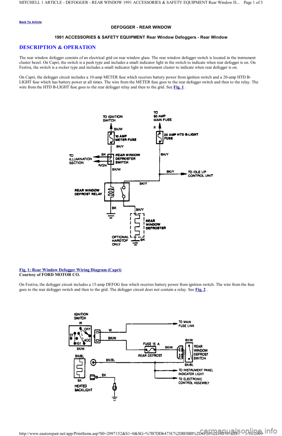
On Capri, the defogger circuit includes a 10-amp METER fuse which receives battery power from ignition switch and a 20-amp HTD B-
LIGHT fuse which has battery power at all times. The wire from the METER fuse goes to the rear defogger switch and then to the relay. The
wire from the HTD B-LIGHT fuse goes to the rear defogger relay and then to the grid. See Fig. 1
.
Fig. 1: Rear Window Defogger Wiring Diagram (Capri)
Courtesy of FORD MOTOR CO.
On Festiva, the defogger circuit includes a 15-amp DEFOG fuse which receives battery power from ignition switch. The wire from the fuse
goes to the rear defogger switch and then to the grid. The defogger circuit does not contain a relay. See Fig. 2
.
Page 1 of 3 MITCHELL 1 ARTICLE - DEFOGGER - REAR WINDOW 1991 ACCESSORIES & SAFETY EQUIPMENT Rear Window D
...
3/10/2009 http://www.eautorepair.net/app/PrintItems.asp?S0=2097152&S1=0&SG=%7B7DD6473C%2DB5BB%2D4F20%2D9D70%2D
...
Page 8 of 454
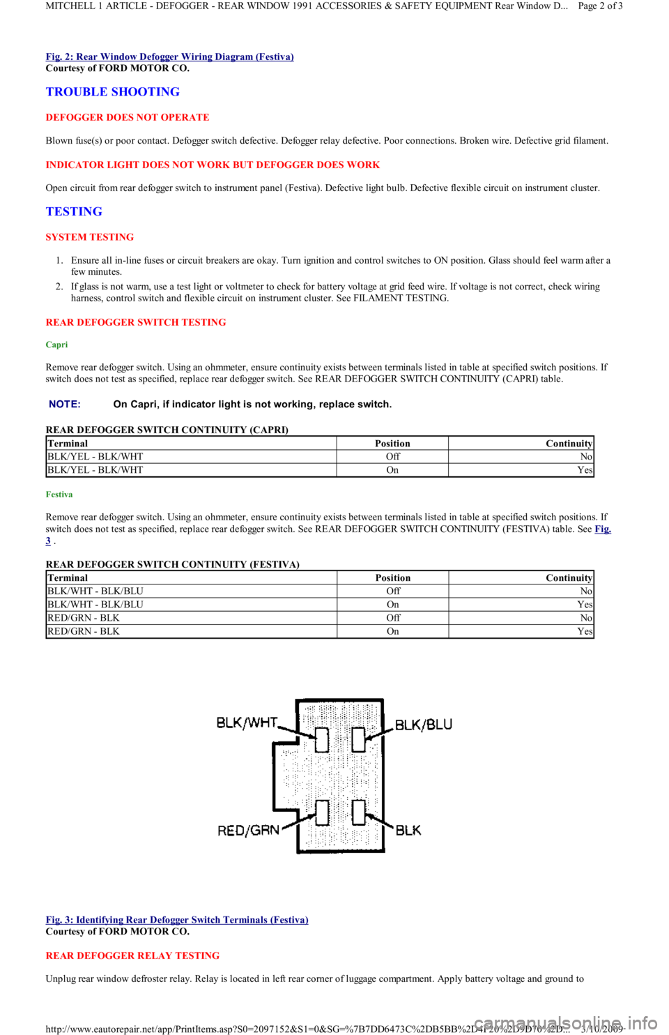
Fig. 2: Rear Window Defogger Wiring Diagram (Festiva)
Courtesy of FORD MOTOR CO.
TROUBLE SHOOTING
DEFOGGER DOES NOT OPERATE
Blown fuse(s) or poor contact. Defogger switch defective. Defogger relay defective. Poor connections. Broken wire. Defective grid filament.
INDICATOR LIGHT DOES NOT WORK BUT DEFOGGER DOES WORK
Open circuit from rear defogger switch to instrument panel (Festiva). Defective light bulb. Defective flexible circuit on instrument cluster.
TESTING
SYSTEM TESTING
1. Ensure all in-line fuses or circuit breakers are okay. Turn ignition and control switches to ON position. Glass should feel warm after a
few min u t es.
2. If glass is not warm, use a test light or voltmeter to check for battery voltage at grid feed wire. If voltage is not correct, check wiring
harness, control switch and flexible circuit on instrument cluster. See FILAMENT TESTING.
REAR DEFOGGER SWITCH TESTING
Capri
Remove rear defogger switch. Using an ohmmeter, ensure continuity exists between terminals listed in table at specified switch positions. If
switch does not test as specified, replace rear defogger switch. See REAR DEFOGGER SWITCH CONTINUITY (CAPRI) table.
REAR DEFOGGER SWITCH CONTINUITY (CAPRI)
Festiva
Remove rear defogger switch. Using an ohmmeter, ensure continuity exists between terminals listed in table at specified switch positions. If
switch does not test as specified, replace rear defogger switch. See REAR DEFOGGER SWITCH CONTINUITY (FESTIVA) table. See Fig.
3 .
REAR DEFOGGER SWITCH CONTINUITY (FESTIVA)
Fig. 3: Identifying Rear Defogger Switch Terminals (Festiva)
Courtesy of FORD MOTOR CO.
REAR DEFOGGER RELAY TESTING
Unplug rear window defroster relay. Relay is located in left rear corner of luggage compartment. Apply battery voltage and ground to NOTE:On Capri, if indicator light is not working, replace switch.
TerminalPositionContinuity
BLK/YEL - BLK/WHTOffNo
BLK/YEL - BLK/WHTOnYes
TerminalPositionContinuity
BLK/WHT - BLK/BLUOffNo
BLK/WHT - BLK/BLUOnYes
RED/GRN - BLKOffNo
RED/GRN - BLKOnYes
Page 2 of 3 MITCHELL 1 ARTICLE - DEFOGGER - REAR WINDOW 1991 ACCESSORIES & SAFETY EQUIPMENT Rear Window D
...
3/10/2009 http://www.eautorepair.net/app/PrintItems.asp?S0=2097152&S1=0&SG=%7B7DD6473C%2DB5BB%2D4F20%2D9D70%2D
...
Page 10 of 454
Back To Article
1990-92 ACCESSORIES & EQUIPMENT
Power Mirrors - Festiva
DESCRIPTION & OPERATION
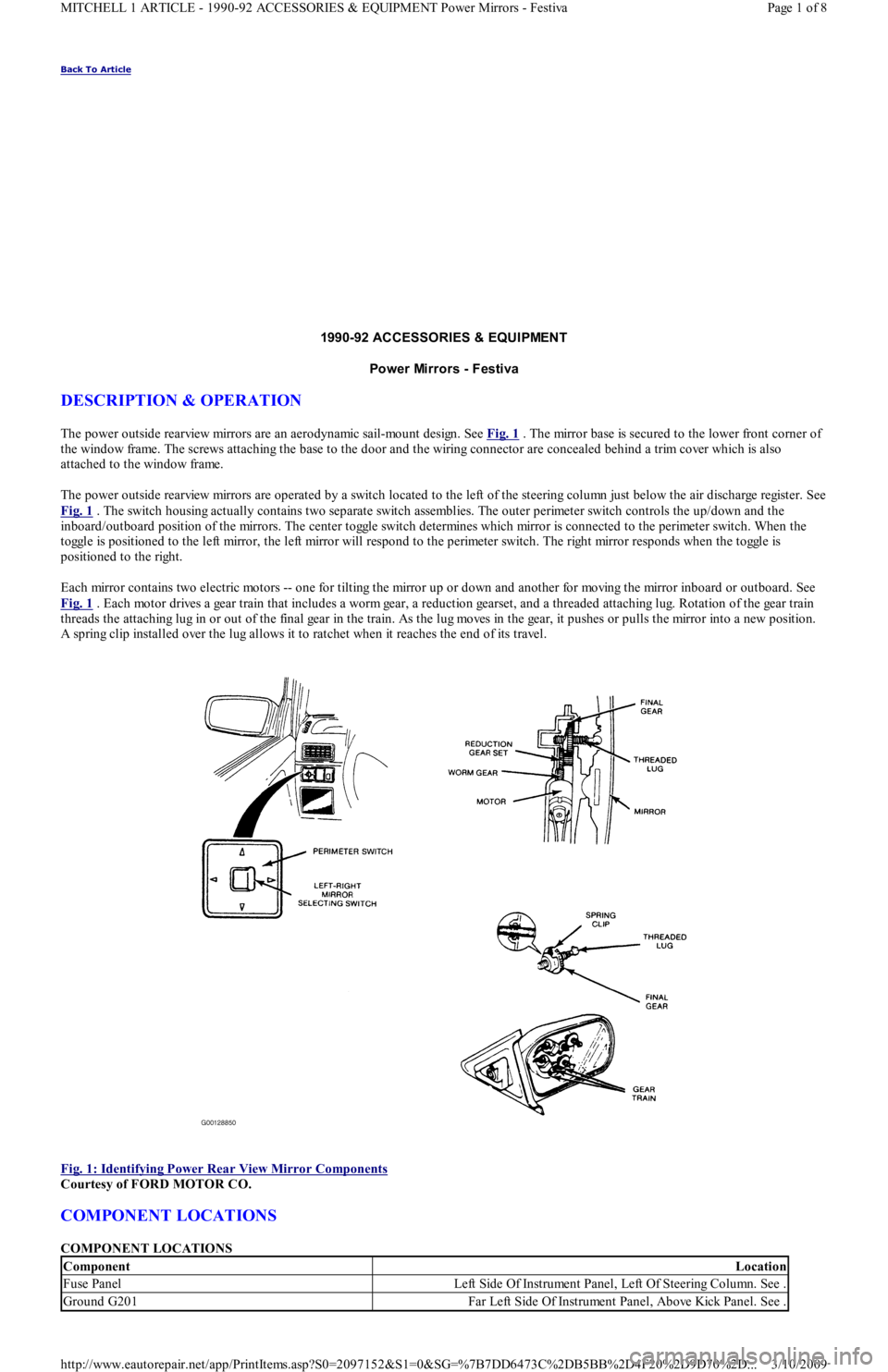
The power outside rearview mirrors are an aerodynamic sail-mount design. See Fig. 1 . The mirror base is secured to the lower front corner of
the window frame. The screws attaching the base to the door and the wiring connector are concealed behind a trim cover which is also
attached to the window frame.
The power outside rearview mirrors are operated by a switch located to the left of the steering column just below the air discharge register. See
Fig. 1
. The switch housing actually contains two separate switch assemblies. The outer perimeter switch controls the up/down and the
inboard/outboard position of the mirrors. The center toggle switch determines which mirror is connected to the perimeter switch. When the
toggle is positioned to the left mirror, the left mirror will respond to the perimeter switch. The right mirror responds when the toggle is
positioned to the right.
Each mirror contains two electric motors -- one for tilting the mirror up or down and another for moving the mirror inboard or outboard. See
Fig. 1
. Each motor drives a gear train that includes a worm gear, a reduction gearset, and a threaded attaching lug. Rotation of the gear train
threads the attaching lug in or out of the final gear in the train. As the lug moves in the gear, it pushes or pulls the mirror into a new position.
A spring clip installed over the lug allows it to ratchet when it reaches the end of its travel.
Fig. 1: Identifying Power Rear View Mirror Components
Courtesy of FORD MOTOR CO.
COMPONENT LOCATIONS
COMPONENT LOCATIONS
ComponentLocation
Fuse PanelLeft Side Of Instrument Panel, Left Of Steering Column. See .
Ground G201Far Left Side Of Instrument Panel, Above Kick Panel. See .
Page 1 of 8 MITCHELL 1 ARTICLE - 1990-92 ACCESSORIES & EQUIPMENT Power Mirrors - Festiva
3/10/2009 http://www.eautorepair.net/app/PrintItems.asp?S0=2097152&S1=0&SG=%7B7DD6473C%2DB5BB%2D4F20%2D9D70%2D
...
Page 11 of 454
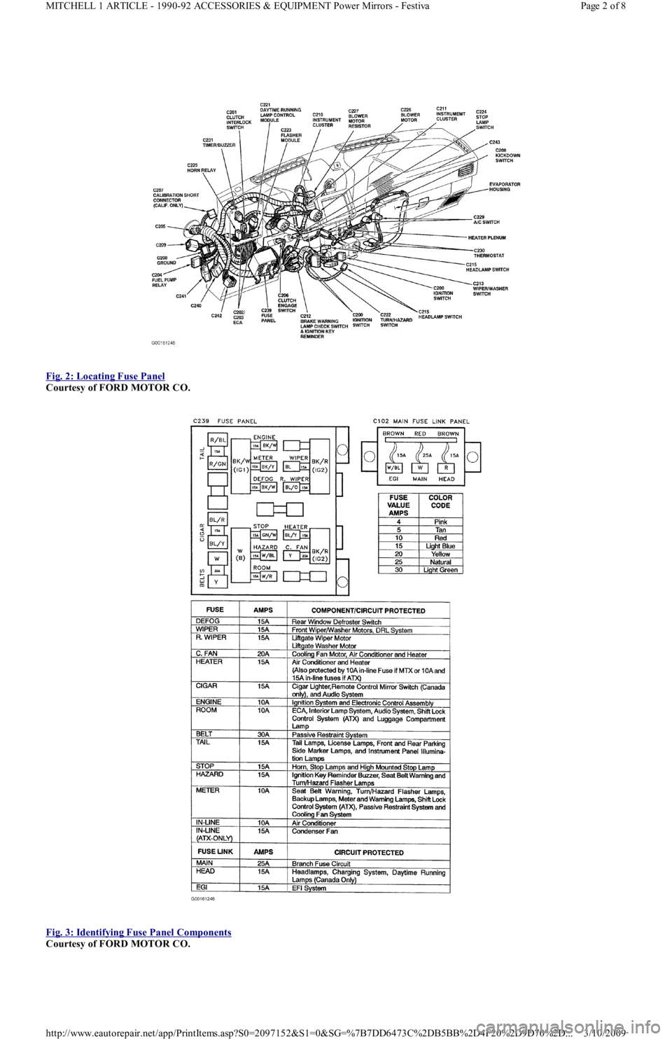
Fig. 2: Locating Fuse Panel
Courtesy of FORD MOTOR CO.
Fig. 3: Identifying Fuse Panel Components
Courtesy of FORD MOTOR CO.
Page 2 of 8 MITCHELL 1 ARTICLE - 1990-92 ACCESSORIES & EQUIPMENT Power Mirrors - Festiva
3/10/2009 http://www.eautorepair.net/app/PrintItems.asp?S0=2097152&S1=0&SG=%7B7DD6473C%2DB5BB%2D4F20%2D9D70%2D
...
Page 12 of 454
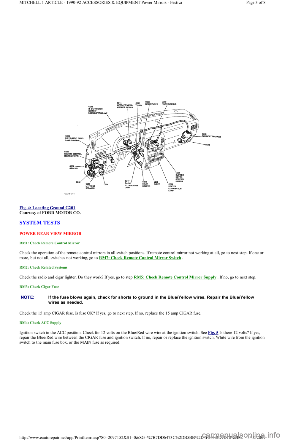
Fig. 4: Locating Ground G201
Courtesy of FORD MOTOR CO.
SYSTEM TESTS
POW ER REAR VIEW MIRROR
RM1: Check Remote Control Mirror
Check the operation of the remote control mirrors in all switch positions. If remote control mirror not working at all, go to next step. If one or
more, but not all, switches not working, go to RM7: Check Remote Control Mirror Switch
.
RM2: Check Related Systems
Check the radio and cigar lighter. Do they work? If yes, go to step RM5: Check Remote Control Mirror Supply . If no, go to next step.
RM3: Check Cigar Fuse
Check the 15 amp CIGAR fuse. Is fuse OK? If yes, go to next step. If no, replace the 15 amp CIGAR fuse.
RM4: Check ACC Supply
Ignition switch in the ACC position. Check for 12 volts on the Blue/Red wire wire at the ignition switch. See Fig. 5 Is there 12 volts? If yes,
repair the Blue/Red wire between the CIGAR fuse and ignition switch. If no, repair or replace the ignition switch, White wire from the ignition
switch to the main fuse box, or the MAIN fuse as required.
NOTE:If the fuse blows again, check for shorts to ground in the Blue/Yellow wires. Repair the Blue/Yellow
wires as needed.
Page 3 of 8 MITCHELL 1 ARTICLE - 1990-92 ACCESSORIES & EQUIPMENT Power Mirrors - Festiva
3/10/2009 http://www.eautorepair.net/app/PrintItems.asp?S0=2097152&S1=0&SG=%7B7DD6473C%2DB5BB%2D4F20%2D9D70%2D
...
Page 13 of 454
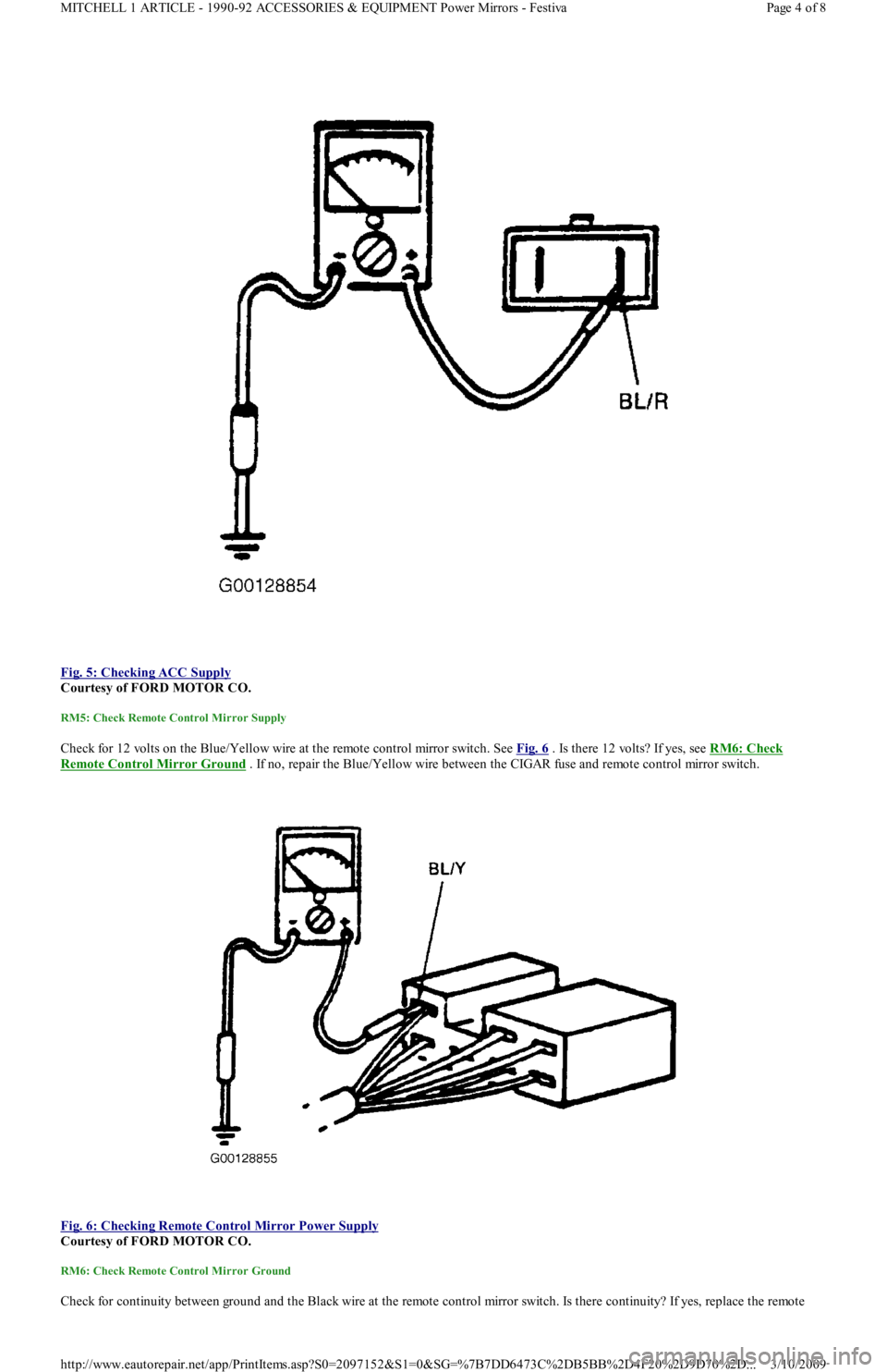
Fig. 5: Checking ACC Supply
Courtesy of FORD MOTOR CO.
RM5: Check Remote Control Mirror Supply
Check for 12 volts on the Blue/Yellow wire at the remote control mirror switch. See Fig. 6 . Is there 12 volts? If yes, see RM6: Check
Remote Control Mirror Ground . If no, repair the Blue/Yellow wire between the CIGAR fuse and remote control mirror switch.
Fig. 6: Checking Remote Control Mirror Power Supply
Courtesy of FORD MOTOR CO.
RM6: Check Remote Control Mirror Ground
Check for continuity between ground and the Black wire at the remote control mirror switch. Is there continuity? If yes, replace the remote
Page 4 of 8 MITCHELL 1 ARTICLE - 1990-92 ACCESSORIES & EQUIPMENT Power Mirrors - Festiva
3/10/2009 http://www.eautorepair.net/app/PrintItems.asp?S0=2097152&S1=0&SG=%7B7DD6473C%2DB5BB%2D4F20%2D9D70%2D
...
Page 14 of 454
control mirror switch. See REMOTE MIRROR SW ITCH under REMOVAL & INSTALLATION. If no, repair the Black wire between the
remote control mirror switch and ground.
RM7: Check Remote Control Mirror Switch
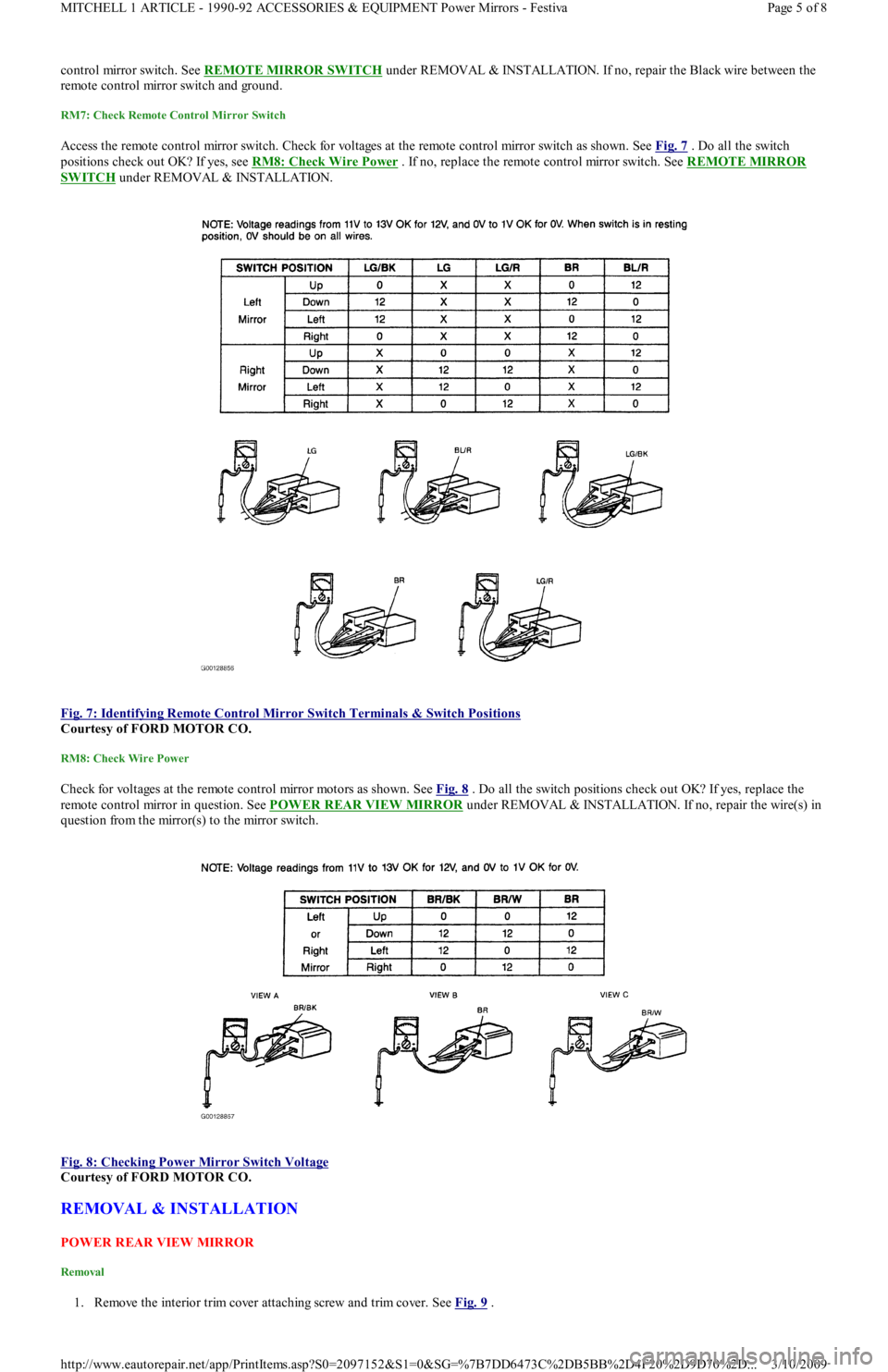
Access the remote control mirror switch. Check for voltages at the remote control mirror switch as shown. See Fig. 7 . Do all the switch
positions check out OK? If yes, see RM8: Check Wire Power . If no, replace the remote control mirror switch. See REMOTE MIRROR
SWITCH under REMOVAL & INSTALLATION.
Fig. 7: Identifying Remote Control Mirror Switch Terminals & Switch Positions
Courtesy of FORD MOTOR CO.
RM8: Check Wire Power
Check for voltages at the remote control mirror motors as shown. See Fig. 8 . Do all the switch positions check out OK? If yes, replace the
remote control mirror in question. See POW ER REAR VIEW MIRROR
under REMOVAL & INSTALLATION. If no, repair the wire(s) in
question from the mirror(s) to the mirror switch.
Fig. 8: Checking Power Mirror Switch Voltage
Courtesy of FORD MOTOR CO.
REMOVAL & INSTALLATION
POW ER REAR VIEW MIRROR
Removal
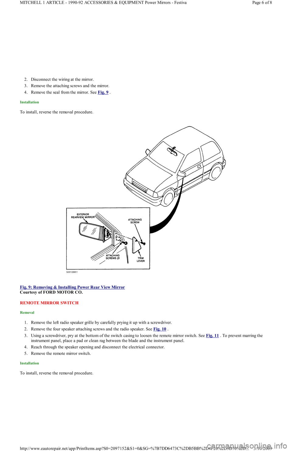
1. Remove the interior trim cover attaching screw and trim cover. See Fig. 9 .
Page 5 of 8 MITCHELL 1 ARTICLE - 1990-92 ACCESSORIES & EQUIPMENT Power Mirrors - Festiva
3/10/2009 http://www.eautorepair.net/app/PrintItems.asp?S0=2097152&S1=0&SG=%7B7DD6473C%2DB5BB%2D4F20%2D9D70%2D
...
Page 15 of 454
2. Disconnect the wiring at the mirror.
3. Remove the attaching screws and the mirror.
4. Remove the seal from the mirror. See Fig. 9
.
Installation
To install, reverse the removal procedure.
Fig. 9: Removing & Installing Power Rear View Mirror
Courtesy of FORD MOTOR CO.
REMOTE MIRROR SWITCH
Removal
1. Remove the left radio speaker grille by carefully prying it up with a screwdriver.
2. Remove the four speaker attaching screws and the radio speaker. See Fig. 10
.
3. Using a screwdriver, pry at the bottom of the switch casing to loosen the remote mirror switch. See Fig. 11
. To prevent marring the
instrument panel, place a pad or clean rag between the blade and the instrument panel.
4. Reach through the speaker opening and disconnect the electrical connector.
5. Remove the remote mirror switch.
Installation
To install, reverse the removal procedure.
Page 6 of 8 MITCHELL 1 ARTICLE - 1990-92 ACCESSORIES & EQUIPMENT Power Mirrors - Festiva
3/10/2009 http://www.eautorepair.net/app/PrintItems.asp?S0=2097152&S1=0&SG=%7B7DD6473C%2DB5BB%2D4F20%2D9D70%2D
...