1991 FORD FESTIVA oil pressure
[x] Cancel search: oil pressurePage 305 of 454
Back To Article
GENERAL INFORMATION
Manual Transmission Trouble Shooting
* PLEASE READ THIS FIRST *
INTRODUCTION
There are many times when the transmission is incorrectly blamed for shifting problems or noises that are actually caused by other reasons.
Shift difficulties are frequently caused by conditions outside of the transmission or transaxle. Typical conditions include: shift linkage, shift
cables, alignment of engine to transmission, worn engine mounts or clutch problems. Drive train noises may come from many sources such as
tires, road surfaces, wheel bearings, differentials, engine or exhaust system. Repairing or overhauling transmission will not cure these
problems.
No manufacturer makes a perfectly quiet transmission. Gear rollover noise is present in most constant mesh transmissions and will tend to
disappear when the clutch is disengaged or transmission is placed in gear. If clutch is properly adjusted, clutch release bearing noise will
disappear when release bearing is moved enough to slide release bearing away from pressure plate.
Trouble shooting can be helped by driving vehicle on a smooth level road to help eliminate tire and body noise. Note whether noise occurs on
acceleration, coasting, deceleration or steady driving conditions. Some problems may only occur when transmission is either hot or cold. Gear
lubricant that is too thick can cause hard shifting on cold mornings before engine is warm and vehicle has been driven.
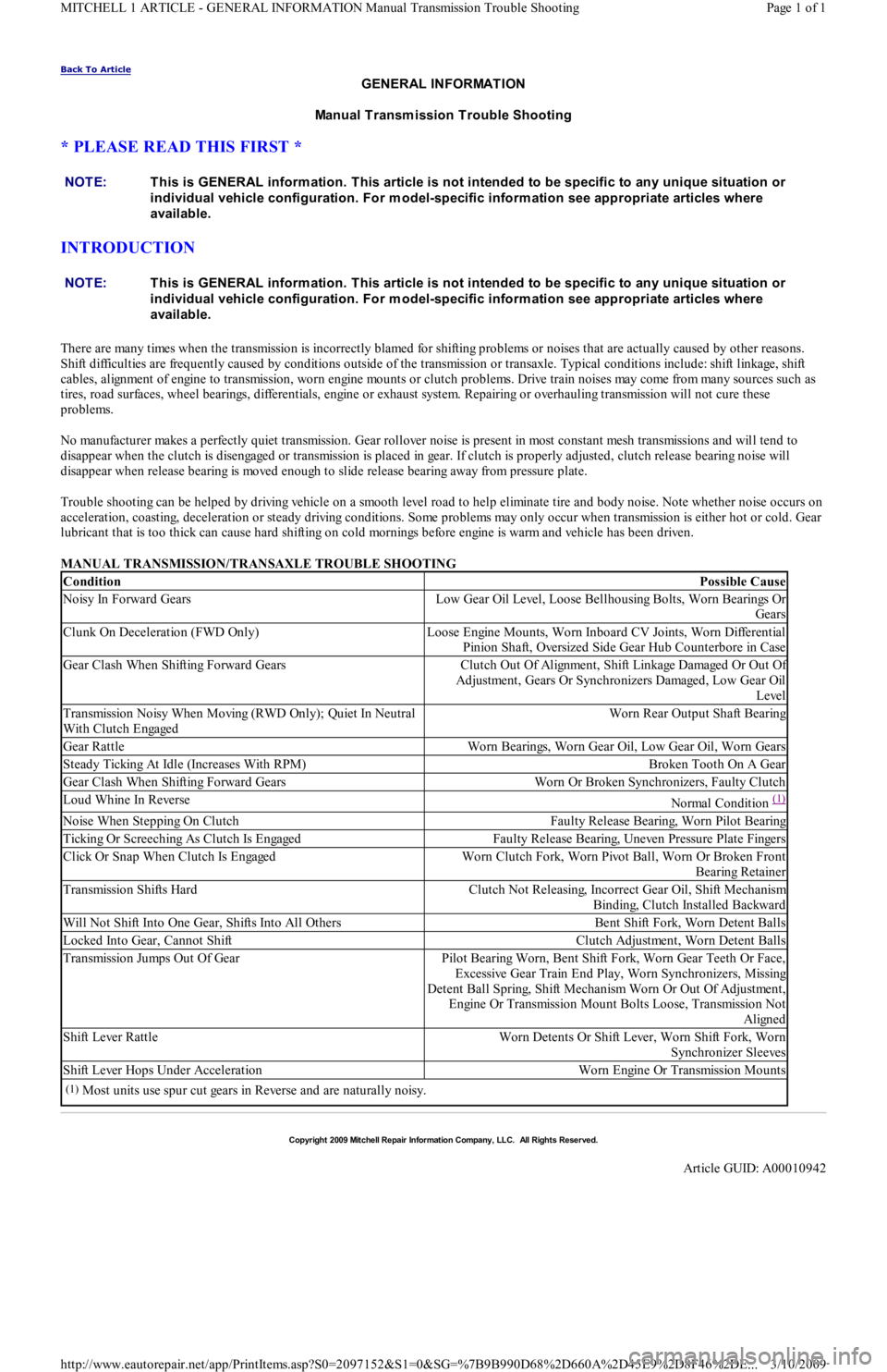
MANUAL TRANSMISSION/TRANSAXLE TROUBLE SHOOTING NOTE:This is GENERAL inform ation. This article is not intended to be specific to any unique situation or
individual vehicle configuration. For m odel-specific inform ation see appropriate articles where
available.
NOTE:This is GENERAL inform ation. This article is not intended to be specific to any unique situation or
individual vehicle configuration. For m odel-specific inform ation see appropriate articles where
available.
ConditionPossible Cause
Noisy In Forward GearsLow Gear Oil Level, Loose Bellhousing Bolts, Worn Bearings Or
Gears
Clunk On Deceleration (FWD Only)Loose Engine Mounts, Worn Inboard CV Joints, Worn Differential
Pinion Shaft, Oversized Side Gear Hub Counterbore in Case
Gear Clash When Shifting Forward GearsClutch Out Of Alignment, Shift Linkage Damaged Or Out Of
Adjustment, Gears Or Synchronizers Damaged, Low Gear Oil
Level
Transmission Noisy When Moving (RWD Only); Quiet In Neutral
With Clutch EngagedWorn Rear Output Shaft Bearing
Gear RattleWorn Bearings, Worn Gear Oil, Low Gear Oil, Worn Gears
Steady Ticking At Idle (Increases With RPM)Broken Tooth On A Gear
Gear Clash When Shifting Forward GearsWorn Or Broken Synchronizers, Faulty Clutch
Loud Whine In ReverseNormal Condition (1)
Noise When Stepping On ClutchFaulty Release Bearing, Worn Pilot Bearing
Ticking Or Screeching As Clutch Is EngagedFaulty Release Bearing, Uneven Pressure Plate Fingers
Click Or Snap When Clutch Is EngagedWorn Clutch Fork, Worn Pivot Ball, Worn Or Broken Front
Bearing Retainer
Transmission Shifts HardClutch Not Releasing, Incorrect Gear Oil, Shift Mechanism
Binding, Clutch Installed Backward
Will Not Shift Into One Gear, Shifts Into All OthersBent Shift Fork, Worn Detent Balls
Locked Into Gear, Cannot ShiftClutch Adjustment, Worn Detent Balls
Transmission Jumps Out Of GearPilot Bearing Worn, Bent Shift Fork, Worn Gear Teeth Or Face,
Excessive Gear Train End Play, Worn Synchronizers, Missing
Detent Ball Spring, Shift Mechanism Worn Or Out Of Adjustment,
Engine Or Transmission Mount Bolts Loose, Transmission Not
Aligned
Shift Lever RattleWorn Detents Or Shift Lever, Worn Shift Fork, Worn
Synchronizer Sleeves
Shift Lever Hops Under AccelerationWorn Engine Or Transmission Mounts
(1)Most units use spur cut gears in Reverse and are naturally noisy.
Copyr ight 2009 Mitchell Repair Information Company, LLC. All Rights Reserved.
Article GUID: A00010942
Page 1 of 1 MITCHELL 1 ARTICLE - GENERAL INFORMATION Manual Transmission Trouble Shooting
3/10/2009 http://www.eautorepair.net/app/PrintItems.asp?S0=2097152&S1=0&SG=%7B9B990D68%2D660A%2D45E9%2D8F46%2DE
...
Page 306 of 454
Back To Article
1991 GENERAL SERVICING
A/C Com pressor Refrigerant Oil Checking
ISOLATING COMPRESSOR
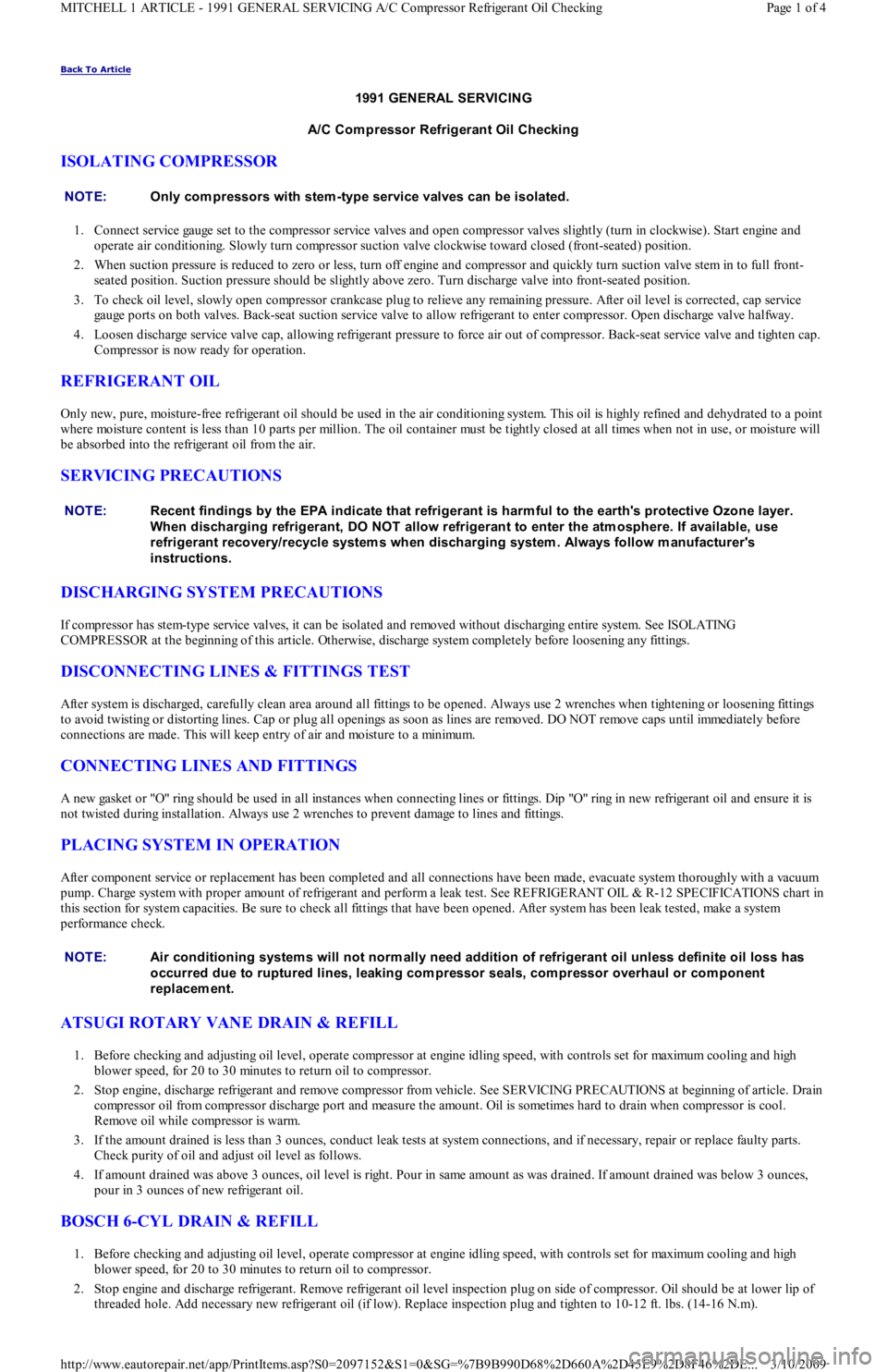
1. Connect service gauge set to the compressor service valves and open compressor valves slightly (turn in clockwise). Start engine and
operate air conditioning. Slowly turn compressor suction valve clockwise toward closed (front-seated) position.
2. When suction pressure is reduced to zero or less, turn off engine and compressor and quickly turn suction valve stem in to full front-
seated position. Suction pressure should be slightly above zero. Turn discharge valve into front-seated position.
3. To check oil level, slowly open compressor crankcase plug to relieve any remaining pressure. After oil level is corrected, cap service
gauge ports on both valves. Back-seat suction service valve to allow refrigerant to enter compressor. Open discharge valve halfway.
4. Loosen discharge service valve cap, allowing refrigerant pressure to force air out of compressor. Back-seat service valve and tighten cap.
Compressor is now ready for operation.
REFRIGERANT OIL
Only new, pure, moisture-free refrigerant oil should be used in the air conditioning system. This oil is highly refined and dehydrated to a point
where moisture content is less than 10 parts per million. The oil container must be tightly closed at all times when not in use, or moisture will
be absorbed into the refrigerant oil from the air.
SERVICING PRECAUTIONS
DISCHARGING SYSTEM PRECAUTIONS
If compressor has stem-type service valves, it can be isolated and removed without discharging entire system. See ISOLATING
COMPRESSOR at the beginning of this article. Otherwise, discharge system completely before loosening any fittings.
DISCONNECTING LINES & FITTINGS TEST
After system is discharged, carefully clean area around all fittings to be opened. Always use 2 wrenches when tightening or loosening fittings
to avoid twisting or distorting lines. Cap or plug all openings as soon as lines are removed. DO NOT remove caps until immediately before
connections are made. This will keep entry of air and moisture to a minimum.
CONNECTING LINES AND FITTINGS
A new gasket or "O" ring should be used in all instances when connecting lines or fittings. Dip "O" ring in new refrigerant oil and ensure it is
not twisted during installation. Always use 2 wrenches to prevent damage to lines and fittings.
PLACING SYSTEM IN OPERATION
After component service or replacement has been completed and all connections have been made, evacuate system thoroughly with a vacuum
pump. Charge system with proper amount of refrigerant and perform a leak test. See REFRIGERANT OIL & R-12 SPECIFICATIONS chart in
this section for system capacities. Be sure to check all fittings that have been opened. After system has been leak tested, make a system
performance check.
ATSUGI ROTARY VANE DRAIN & REFILL
1. Before checking and adjusting oil level, operate compressor at engine idling speed, with controls set for maximum cooling and high
blower speed, for 20 to 30 minutes to return oil to compressor.
2. Stop engine, discharge refrigerant and remove compressor from vehicle. See SERVICING PRECAUTIONS at beginning of article. Drain
compressor oil from compressor discharge port and measure the amount. Oil is sometimes hard to drain when compressor is cool.
Remove oil while compressor is warm.
3. If the amount drained is less than 3 ounces, conduct leak tests at system connections, and if necessary, repair or replace faulty parts.
Check purity of oil and adjust oil level as follows.
4. If amount drained was above 3 ounces, oil level is right. Pour in same amount as was drained. If amount drained was below 3 ounces,
pour in 3 ounces of new refrigerant oil.
BOSCH 6-CYL DRAIN & REFILL
1. Before checking and adjusting oil level, operate compressor at engine idling speed, with controls set for maximum cooling and high
blower speed, for 20 to 30 minutes to return oil to compressor.
2. Stop engine and discharge refrigerant. Remove refrigerant oil level inspection plug on side of compressor. Oil should be at lower lip of
threaded hole. Add necessary new refrigerant oil (if low). Replace inspection plug and tighten to 10-12 ft. lbs. (14-16 N.m). NOTE:Only com pressors with stem -type service valves can be isolated.
NOTE:Recent findings by the EPA indicate that refrigerant is harm ful to the earth's protective Ozone layer.
When discharging refrigerant, DO NOT allow refrigerant to enter the atm osphere. If available, use
refrigerant recovery/recycle system s when discharging system . Always follow m anufacturer's
instructions.
NOTE:Air conditioning system s will not norm ally need addition of refrigerant oil unless definite oil loss has
occurred due to ruptured lines, leaking com pressor seals, com pressor overhaul or com ponent
replacem ent.
Page 1 of 4 MITCHELL 1 ARTICLE - 1991 GENERAL SERVICING A/C Compressor Refrigerant Oil Checking
3/10/2009 http://www.eautorepair.net/app/PrintItems.asp?S0=2097152&S1=0&SG=%7B9B990D68%2D660A%2D45E9%2D8F46%2DE
...
Page 311 of 454
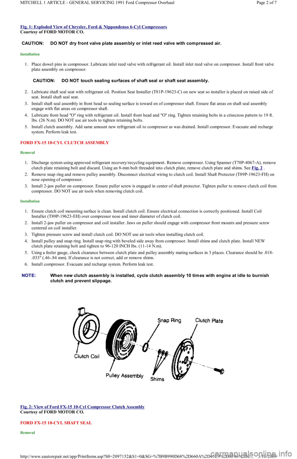
Fig. 1: Exploded View of Chrysler, Ford & Nippondenso 6-Cyl Compressors
Courtesy of FORD MOTOR CO.
Installation
1. Place dowel pins in compressor. Lubricate inlet reed valve with refrigerant oil. Install inlet reed valve on compressor. Install front valve
plate assembly on compressor.
2. Lubricate shaft seal seat with refrigerant oil. Position Seat Installer (T81P-19623-C) on new seat so installer is placed on raised side of
seat. Install shaft seal seat.
3. Install shaft seal assembly in front head so sealing surface is toward en of compressor shaft. Ensure flat areas on shaft seal assembly
engage with flat areas on compressor shaft.
4. Lubricate front head "O" ring with refrigerant oil. Install front head and "O" ring. Tighten retaining bolts in a crisscross pattern to 19 ft.
lbs. (26 N.m). DO NOT use air tools to tighten retaining bolts.
5. Install clutch assembly. Add same amount new refrigerant oil to compressor as was drained. Install compressor. Evacuate and recharge
system. Perform leak test.
FORD FX-15 10-CYL CLUTCH ASSEMBLY
Removal
1. Discharge system using approved refrigerant recovery/recycling equipment. Remove compressor. Using Spanner (T70P-4067-A), remove
clutch plate retaining bolt and discard. Using an 8-mm bolt threaded into clutch plate, remove clutch plate and shims. See Fig. 2
.
2. Remove snap ring and remove pulley assembly. Disconnect electrical wiring to clutch coil. Install Shaft Protector (T89P-19623-FH) on
nose opening of compressor.
3. Install 2-jaw puller on compressor. Ensure puller screw is engaged in center of shaft protector. Tighten puller to remove clutch coil from
compressor. DO NOT use air tools when removing clutch coil.
Installation
1. Ensure clutch coil mounting surface is clean. Install clutch coil. Ensure electrical connection is correctly positioned. Install Coil
Installer (T89P-19623-EH) over compressor nose and inner diameter of clutch coil.
2. Install 2-jaw puller on compressor and coil installer. Jaws on puller should engage with compressor front mounts and pressure screw
centered on coil installer.
3. Tighten pressure screw and install clutch coil. DO NOT use air tools when installing clutch coil.
4. Install pulley and snap ring. Install snap ring with beveled side away from compressor. Install shims and clutch plate. Install NEW
clutch plate retaining bolt and tighten to 96-120 INCH lbs. (11-14 N.m).
5. Using a feeler gauge, check clearance between clutch plate and pulley assembly mating surfaces in 3 places. Clearance should be .018-
.033" (.46-.84 mm). If clearance is not correct, add or remove shims.
6. Install compressor. Evacuate and recharge system. Perform leak test.
Fig. 2: View of Ford FX
-15 10-Cyl Compressor Clutch Assembly
Courtesy of FORD MOTOR CO.
FORD FX-15 10-CYL SHAFT SEAL
Removal
CAUT ION: DO NOT dry front valve plate assem bly or inlet reed valve with com pressed air.
CAUT ION: DO NOT touch sealing surfaces of shaft seal or shaft seat assem bly.
NOTE:When new clutch assem bly is installed, cycle clutch assem bly 10 tim es with engine at idle to burnish
clutch and prevent slippage.
Page 2 of 7 MITCHELL 1 ARTICLE - GENERAL SERVICING 1991 Ford Compressor Overhaul
3/10/2009 http://www.eautorepair.net/app/PrintItems.asp?S0=2097152&S1=0&SG=%7B9B990D68%2D660A%2D45E9%2D8F46%2DE
...
Page 317 of 454
Back To Article
A/C COMPRESSOR SERVICING
1991 GENERAL SERVICING Com pressor Service
ISOLATING COMPRESSOR
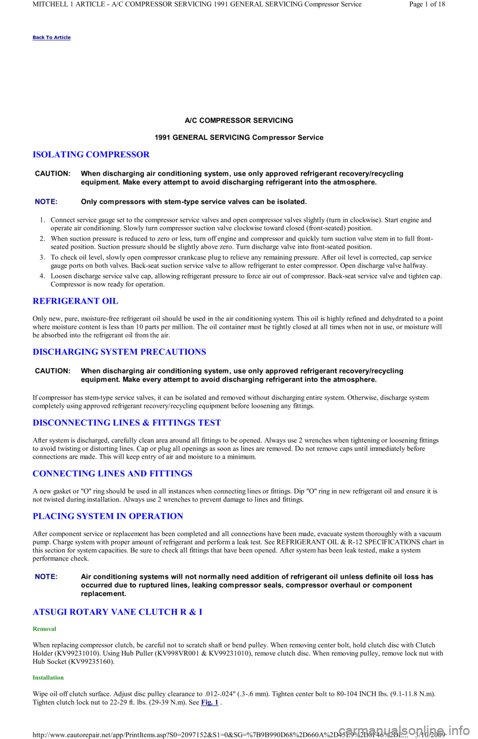
1. Connect service gauge set to the compressor service valves and open compressor valves slightly (turn in clockwise). Start engine and
operate air conditioning. Slowly turn compressor suction valve clockwise toward closed (front-seated) position.
2. When suction pressure is reduced to zero or less, turn off engine and compressor and quickly turn suction valve stem in to full front-
seated position. Suction pressure should be slightly above zero. Turn discharge valve into front-seated position.
3. To check oil level, slowly open compressor crankcase plug to relieve any remaining pressure. After oil level is corrected, cap service
gauge ports on both valves. Back-seat suction service valve to allow refrigerant to enter compressor. Open discharge valve halfway.
4. Loosen discharge service valve cap, allowing refrigerant pressure to force air out of compressor. Back-seat service valve and tighten cap.
Compressor is now ready for operation.
REFRIGERANT OIL
Only new, pure, moisture-free refrigerant oil should be used in the air conditioning system. This oil is highly refined and dehydrated to a point
where moisture content is less than 10 parts per million. The oil container must be tightly closed at all times when not in use, or moisture will
be absorbed into the refrigerant oil from the air.
DISCHARGING SYSTEM PRECAUTIONS
If compressor has stem-type service valves, it can be isolated and removed without discharging entire system. Otherwise, discharge system
completely using approved refrigerant recovery/recycling equipment before loosening any fittings.
DISCONNECTING LINES & FITTINGS TEST
After system is discharged, carefully clean area around all fittings to be opened. Always use 2 wrenches when tightening or loosening fittings
to avoid twisting or distorting lines. Cap or plug all openings as soon as lines are removed. Do not remove caps until immediately before
connections are made. This will keep entry of air and moisture to a minimum.
CONNECTING LINES AND FITTINGS
A new gasket or "O" ring should be used in all instances when connecting lines or fittings. Dip "O" ring in new refrigerant oil and ensure it is
not twisted during installation. Always use 2 wrenches to prevent damage to lines and fittings.
PLACING SYSTEM IN OPERATION
After component service or replacement has been completed and all connections have been made, evacuate system thoroughly with a vacuum
pump. Charge system with proper amount of refrigerant and perform a leak test. See REFRIGERANT OIL & R-12 SPECIFICATIONS chart in
this section for system capacities. Be sure to check all fittings that have been opened. After system has been leak tested, make a system
performance check.
ATSUGI ROTARY VANE CLUTCH R & I
Removal
When replacing compressor clutch, be careful not to scratch shaft or bend pulley. When removing center bolt, hold clutch disc with Clutch
Holder (KV99231010). Using Hub Puller (KV998VR001 & KV99231010), remove clutch disc. When removing pulley, remove lock nut with
Hub Socket (KV99235160).
Installation
Wipe oil off clutch surface. Adjust disc pulley clearance to .012-.024" (.3-.6 mm). Tighten center bolt to 80-104 INCH lbs. (9.1-11.8 N.m).
Tighten clutch lock nut to 22-29 ft. lbs. (29-39 N.m). See Fig. 1
. CAUT ION: When discharging air conditioning system , use only approved refrigerant recovery/recycling
equipm ent. Make every attem pt to avoid discharging refrigerant into the atm osphere.
NOTE:Only com pressors with stem -type service valves can be isolated.
CAUT ION: When discharging air conditioning system , use only approved refrigerant recovery/recycling
equipm ent. Make every attem pt to avoid discharging refrigerant into the atm osphere.
NOTE:Air conditioning system s will not norm ally need addition of refrigerant oil unless definite oil loss has
occurred due to ruptured lines, leaking com pressor seals, com pressor overhaul or com ponent
replacem ent.
Page 1 of 18 MITCHELL 1 ARTICLE - A/C COMPRESSOR SERVICING 1991 GENERAL SERVICING Compressor Service
3/10/2009 http://www.eautorepair.net/app/PrintItems.asp?S0=2097152&S1=0&SG=%7B9B990D68%2D660A%2D45E9%2D8F46%2DE
...
Page 326 of 454
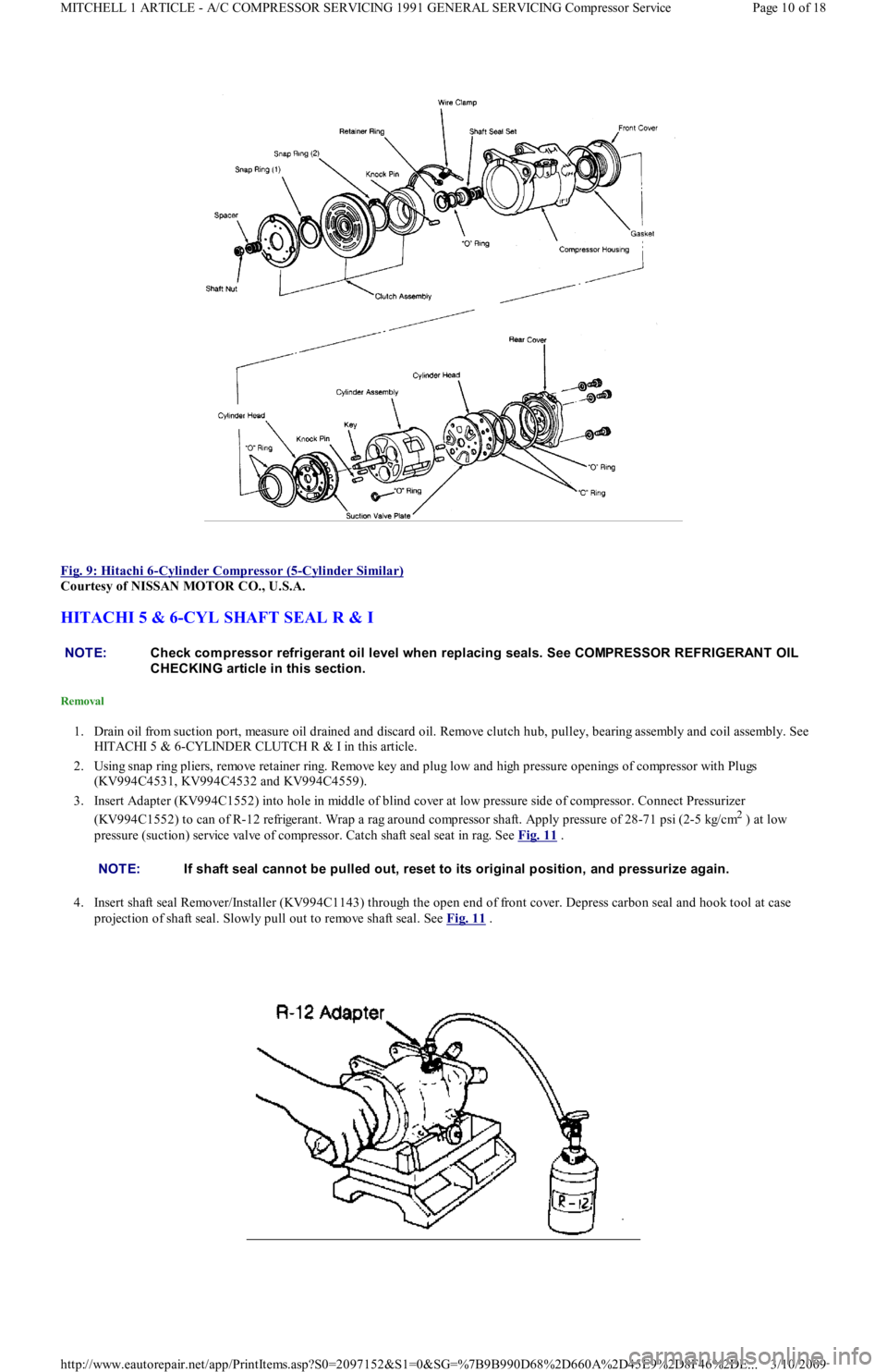
Fig. 9: Hitachi 6
-Cylinder Compressor (5-Cylinder Similar)
Courtesy of NISSAN MOTOR CO., U.S.A.
HITACHI 5 & 6-CYL SHAFT SEAL R & I
Removal
1. Drain oil from suction port, measure oil drained and discard oil. Remove clutch hub, pulley, bearing assembly and coil assembly. See
HITACHI 5 & 6-CYLINDER CLUTCH R & I in this article.
2. Using snap ring pliers, remove retainer ring. Remove key and plug low and high pressure openings of compressor with Plugs
(KV994C4531, KV994C4532 and KV994C4559).
3. Insert Adapter (KV994C1552) into hole in middle of blind cover at low pressure side of compressor. Connect Pressurizer
(KV994C1552) to can of R-12 refrigerant. Wrap a rag around compressor shaft. Apply pressure of 28-71 psi (2-5 kg/cm
2 ) at low
pressure (suction) service valve of compressor. Catch shaft seal seat in rag. See Fig. 11
.
4. Insert shaft seal Remover/Installer (KV994C1143) through the open end of front cover. Depress carbon seal and hook tool at case
projection of shaft seal. Slowly pull out to remove shaft seal. See Fig. 11
.
NOTE:Check com pressor refrigerant oil level when replacing seals. See COMPRESSOR REFRIGERANT OIL
CHECKING article in this section.
NOTE:If shaft seal cannot be pulled out, reset to its original position, and pressurize again.
Page 10 of 18 MITCHELL 1 ARTICLE - A/C COMPRESSOR SERVICING 1991 GENERAL SERVICING Compressor Service
3/10/2009 http://www.eautorepair.net/app/PrintItems.asp?S0=2097152&S1=0&SG=%7B9B990D68%2D660A%2D45E9%2D8F46%2DE
...
Page 329 of 454
Courtesy of MAZDA MOTORS CO., U.S.A.
NIPPONDENSO 6 & 10-CYL CLUTCH R & I
Removal
1. Remove A/C compressor. Remove pressure plate shaft bolt using socket wrench and Clutch Stopper (07112-76060). Install Clutch
Remover (07112-66040) on pressure plate. Using clutch stopper and socket wrench, rotate clutch remover to remove pressure plate.
2. Remove shims from pressure plate. Remove snap ring from compressor. Tap rotor off shaft with plastic hammer. Disconnect stator wire
from housing. Remove snap ring from inside stator. Remove stator. See Fig. 12
.
Installation
To install, reverse removal procedure. Ensure snap rings are installed with beveled side up. tighten shaft bolt to 10 ft. lbs. 14 N.m). Ensure
clutch clearance is .014-.026" (.36-66 mm). adjust clearance by adding or subtracting shims as necessary.
NIPPONDENSO 6 & 10-CYL SHAFT SEAL R & I
Removal
1. Hold clutch hub stationary and remove center nut. Screw remover into center of hub. Turn center bolt to remove pressure plate.
2. Remove shims from shaft. Remove snap ring from inside of pulley. Tap pulley off of shaft with plastic mallet. Be careful not to distort
pulley while removing.
3. Disconnect clutch coil wires from compressor housing. remove snap ring inside coil and lift coil off compressor. Pry dust seal out from
around compressor shaft (if equipped).
4. Place shaft key remover on shaft and turn to remove key. Remove drain plug (if equipped). Remove service valves-to-compressor body
bolts. Remove valves. Discard "O" rings. Drain oil out of compressor.
5. Remove 6 through bolts from front head of compressor and discard washers. Tap head loose from compressor; be careful not to scratch
sealing surfaces. remove snap ring (if equipped) from front housing. Press seal plate out. Remove seal from shaft. See Fig. 14
.
Installation
1. Lubricate shaft seal with clean refrigerant oil and place on compressor shaft. Lubricate seal plate and "O" ring (if equipped) and install
in front housing. Install snap ring (if equipped).
2. Place front housing on compressor body. Install through bolts with new washers. Tighten bolts evenly and alternately to 18 ft. lbs. (24
N.m). Install shaft key using installer and plastic mallet. Insert dust seal into front of compressor.
3. Install drain plug with new gasket. Add correct amount of refrigerant oil to compressor. If service valves were removed, coat n ew "O"
rings with refrigerant oil and install service valves.
4. Place clutch coil on compressor and install snap ring. Install shims on shaft to adjust pressure plate-to-rotor clearance to .016-
.028" (.41-.71 mm). Tighten shaft nut to 12 ft. lbs. (16 N.m). CAUTION: DO NOT dam age pulley when tapping on rotor.
NOTE:Check com pressor refrigerant oil level when replacing seals. See COMPRESSOR OIL CHECKING article
in the AIR CONDIT IONING & HEAT section.
Page 13 of 18 MITCHELL 1 ARTICLE - A/C COMPRESSOR SERVICING 1991 GENERAL SERVICING Compressor Service
3/10/2009 http://www.eautorepair.net/app/PrintItems.asp?S0=2097152&S1=0&SG=%7B9B990D68%2D660A%2D45E9%2D8F46%2DE
...
Page 338 of 454
compressor label before adding refrigerant oil to A/C compressor/system. See Fig. 2 . The following R-134a refrigerant oils are currently
available.
Lexus
PAG Refrigerant Oil (ND-OIL 8) with 10P/10PA swashplate (piston) compressor. Synthetic Refrigerant Oil (ND-OIL 9) with through-va n e
(rotary vane) compressor.
Mercedes-Benz
PAG Refrigerant Oil (001 989 08 03).
Nissan
PAG Refrigerant Oil (KLH00-PAGR0) with rotary vane compressor. PAG Refrigerant Oil (KLH00-PAGS0) with piston (swashplate)
compressor.
Saab
PAG Refrigerant Oil (40 74 787).
SERVICE EQUIPMENT
Because R-134a is not interchangeable with R-12, separate sets of hoses, manifold gauge set and recovery/recycling equipment are required to
service vehicles. This is necessary to avoid cross-contaminating and damaging system.
All equipment used to service systems using R-134a must meet SAE standard J1991. The service hoses on the manifold gauge set must have
manual (turn wheel) or automatic back-flow valves at the service port connector ends. This will prevent refrigerant from being released into
the atmosphere.
For identification purposes, R-134a service hoses must have a Black stripe along its length and be clearly labeled SAE J2196/R-134a. The low
pressure test hose is Blue with a Black stripe. The high pressure test hose is Red with a Black stripe, and the center test hose is Yellow with a
Black stripe.
R-134a manifold gauge sets can be identified by one or all of the following.
Labeled FOR USE WITH R-134a on set
Labeled HFC-134 or R-134a on gauge face
Light Blue color on gauge face
In addition, pressure/temperature scales on R-134a gauge sets are different from R-12 manifold gauge sets.
SYSTEM SERVICE VALVES
SCHRADER-TYPE VALVES
Schrader valve is similar in construction and operation to a tire valve. When a test gauge hose with built-in valve core depressor is attached,
Schrader stem is pushed inward to the open position and allows system pressure to reach gauge.
If test hose does not have a built-in core depressor, an adapter must be used. Never attach hose or adapter to Schrader valve unless it is first
connected to manifold gauge set.
Refrigerant R-12 Schrader-type valve cores have TV5 thread size. Refrigerant R-134a Schrader-type valve cores use M6 (Metric) threads. R-
134a valve cores can be easily identified by use of "O" rings and external spring. See Fig. 1
.
SERVICE VALVE LOCATIONS
SERVICE VALVE LOCATIONS NOTE:Synthetic/PAG oils absorb m oisture very rapidly, 2.3-5.6% by weight, as com pared to a m ineral oil
absorption rate of .005% by weight.
NOTE:Refrigerant R-12 service hoses will ONLY be labeled SAE J2196.
NOTE:Although sim ilar in construction and operation to a tire valve, NEVER replace a Schrader-type valve
with a tire valve.
VehicleHighLow
Audi(14) (15)
Acura(2) (3)
BMW(4) (5)
Chrysler, Eagle & Mitsubishi
Colt, Mirage & Summit(10) (11)
Colt Vista & Summit Wagon(10) (11)
Diamante(1) (1)
Eclipse & Expo(10) (11)
Galant(10) (11)
Page 4 of 6 MITCHELL 1 ARTICLE - 1991-92 AIR CONDITIONING & HEATING A/C System General Servicing
3/10/2009 http://www.eautorepair.net/app/PrintItems.asp?S0=2097152&S1=0&SG=%7B9B990D68%2D660A%2D45E9%2D8F46%2DE
...
Page 341 of 454
Back To Article
A/C SYST EM PRECAUT IONS
A/C GENERAL SERVICING A/C System Servicing cautions
BEFORE OPENING THE SYSTEM
Before disconnecting any lines or fittings, the system must be completely discharged using approved refrigerant recovery/recycling equipment.
DISCHARGING A/C SYSTEM
1. Remove service valve caps and install gauges. For high side gauge hose, Adapter (D81L-19703-A) must be used to connect to high side
service valve.
2. Place open end of center hose in garage exhaust outlet or in a well ventilated area. Slightly open low side gauge valve and let refrigerant
escape slowly without loosing refrigerant oil.
3. When system is nearly discharged, using approved refrigerant recovery/recycling equipment, open high side gauge valve to release any
pressure trapped in compressor. Close valves immediately after discharging to prevent entry of moisture.
DISCONNECTING LINES & FITTINGS
1. After system is discharged, using approved refrigerant recovery/recycling equipment, carefully clean entire area around coupling nut to
prevent dirt entering system. Always use two wrenches to avoid twisting or distorting lines and fittings (hold fitting with one wrench
while loosening coupling nut with second wrench).
2. Ford spring-coupling fittings require a special coupling tool (Motorcraft YT-1056) to open or close. See procedure under Connecting
Lines and Fittings.
3. Cap or plug all LINES and FITTINGS immediately to prevent entry of air and moisture into system. Do not remove these caps until
connections are being made.
COMPONENT REPLACEMENT
When components are replaced, system oil level must be adjusted. Add refrigeration oil to replacement component. See Compressor oil Check
article, as well as COMPONENT OIL REPLACEMENT QUANTITIES chart under A/C SYSTEM SPECS article in this section.
USING R-12 REFRIGERANT - SAFETY PRECAUTIONS
1. Always work in a well-ventilated, clean area. Refrigerant (R-12) is heavier than oxygen, and will displace oxygen in a confined area.
Always wear eye protection when working around air conditioning systems and R-12. The system's high pressure can cause severe injury
to eyes and skin if a hose were to burst. R-12 evaporates quickly when exposed to atmosphere, freezing anything it contacts.
2. Use care when handling refrigerant containers. DO NOT drop or strike containers or expose refrigerant containers to excessive heat.
Containers must never be heated more than 125°F (52°C). Never expose R-12 directly to open flame.
USING INDIVIDUAL R-12 CANS
Disposable refrigerant cans (referred to as one pound cans) have a flat type seal or a screw type seal, and proper can tap must be used for each
type. Be sure sealing gasket on can tap is in good condition. A proper safety can tap will prevent refrigerant from flowing back into open can,
as tap has a one-way flow control.
MULTI-CAN DISPENSING VALVES
A multi-can dispensing valve allows attachment of several cans of refrigerant, and is a good substitute when a bulk container is not available.
Cans are installed onto each leg of multi-can dispensing valve in the same manner as the individual cans, and each leg has its own can tap.
CAN TAP INSTALLATION FLAT TYPE SEAL CANS
On cam-lock or one-piece can taps, first turn the handle outward to the fully open position. Securely engage locking lugs over the can flange,
and lock them in place by turning cam lock or locking nut. Screw tap assembly into adapter so sealing gasket is fully seated against the can
top. Turn tap inward to pierce the can and close the tap. DO NOT open tap until ready to purge the service hose or dispense refrigerant into
the system.
On 2-piece can taps, be certain tap handle is turned fully inward to the closed position. Check that locking base is turned to its outer limit.
Securely engage locking lugs over the can flange. Turn entire tap assembly (without disturbing the closed setting) downward into the locking
base to pierce the can. DO NOT open tap until ready to dispense into system. CAUT ION: When discharging air conditioning system , use only approved refrigerant recovery/recycling
equipm ent. Make every attem pt to avoid discharging refrigerant into the atm osphere.
NOTE:Recent findings by the EPA indicate that R-11, R-12 and R-113 are harm ful to the Earths' protective
Ozone layer. Make every attem pt possible, to avoid discharging R-11, R-12 or R-113 into the
atm osphere.
CAUT ION: When R-12 is exposed to an open flam e, drawn into a running engine, or detected with a Halide
(propane) leak tester, poisonous phosgene gas is form ed. Keep work areas ventilated and avoid
running engines near work area.
NOTE:Recent findings by the EPA indicate that refrigerant is harm ful to the Earth's protective Ozone layer.
When discharging refrigerant avoid allowing refrigerant to enter the atm osphere. Refrigerant recovery
system should be used when discharging the system .
Page 1 of 2 MITCHELL 1 ARTICLE - A/C SYSTEM PRECAUTIONS A/C GENERAL SERVICING A/C System Servicing cautions
3/10/2009 http://www.eautorepair.net/app/PrintItems.asp?S0=2097152&S1=0&SG=%7B9B990D68%2D660A%2D45E9%2D8F46%2DE
...