Page 350 of 454
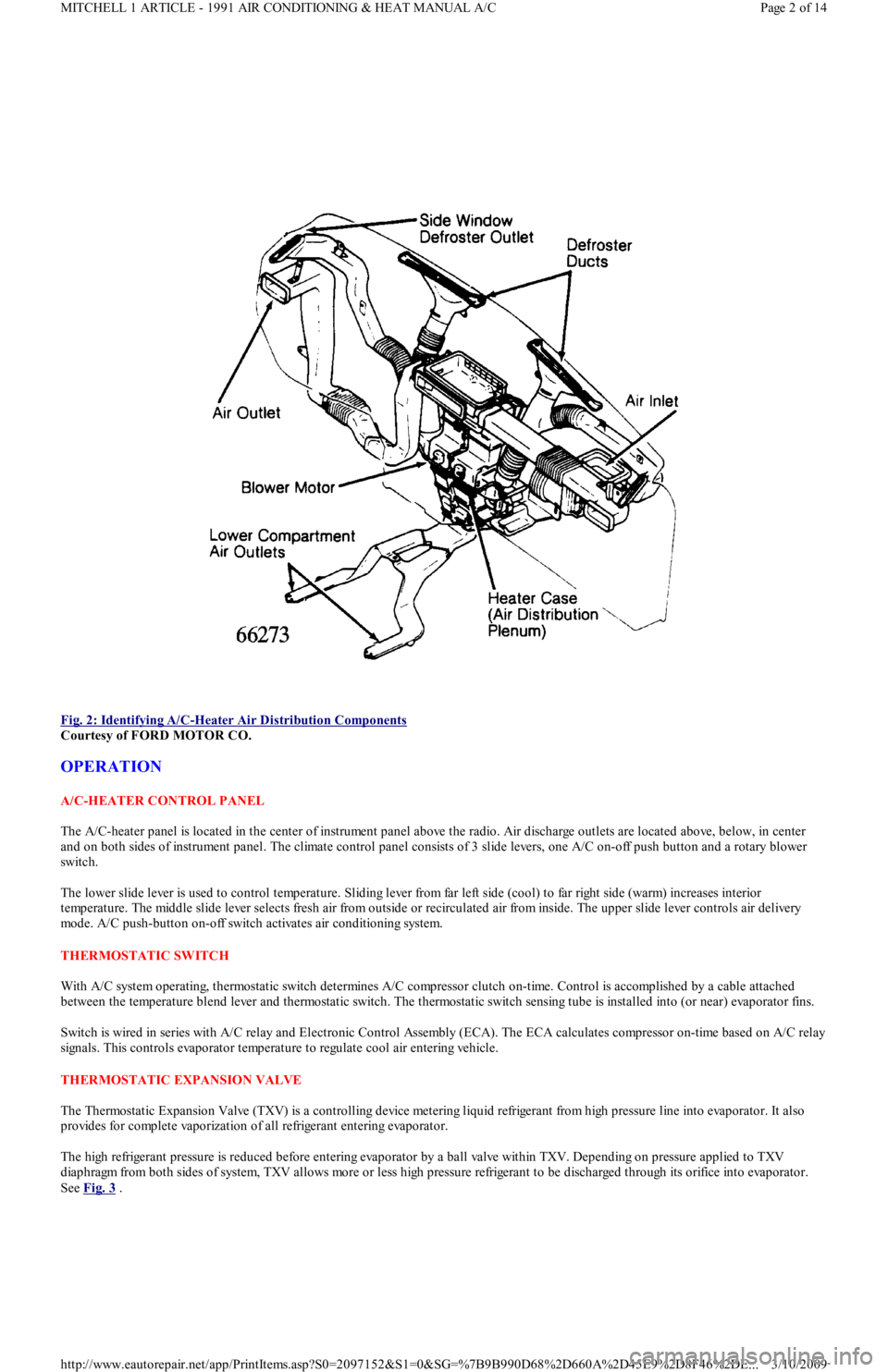
Fig. 2: Identifying A/C
-Heater Air Distribution Components
Courtesy of FORD MOTOR CO.
OPERATION
A/C-HEATER CONTROL PANEL
The A/C-heater panel is located in the center of instrument panel above the radio. Air discharge outlets are located above, below, in center
and on both sides of instrument panel. The climate control panel consists of 3 slide levers, one A/C on-off push button and a rotary blower
switch.
The lower slide lever is used to control temperature. Sliding lever from far left side (cool) to far right side (warm) increases interior
temperature. The middle slide lever selects fresh air from outside or recirculated air from inside. The upper slide lever controls air delivery
mode. A/C push-button on-off switch activates air conditioning system.
THERMOSTATIC SW ITCH
With A/C system operating, thermostatic switch determines A/C compressor clutch on-time. Control is accomplished by a cable attached
between the temperature blend lever and thermostatic switch. The thermostatic switch sensing tube is installed into (or near) evaporator fins.
Switch is wired in series with A/C relay and Electronic Control Assembly (ECA). The ECA calculates compressor on-time based on A/C relay
signals. This controls evaporator temperature to regulate cool air entering vehicle.
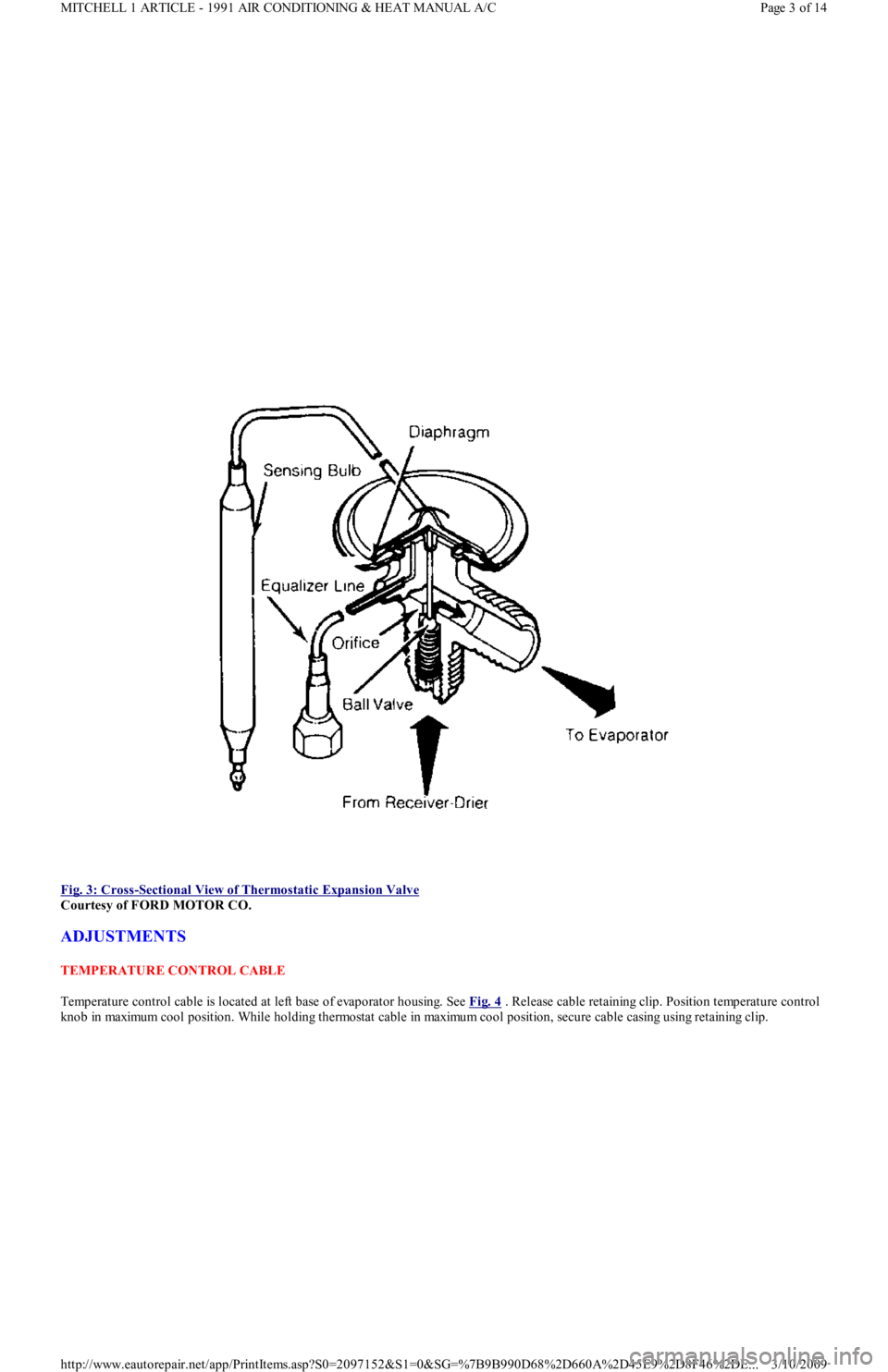
THERMOSTATIC EXPANSION VALVE
The Thermostatic Expansion Valve (TXV) is a controlling device metering liquid refrigerant from high pressure line into evaporator. It also
provides for complete vaporization of all refrigerant entering evaporator.
The high refrigerant pressure is reduced before entering evaporator by a ball valve within TXV. Depending on pressure applied to TXV
diaphragm from both sides of system, TXV allows more or less high pressure refrigerant to be discharged through its orifice into evaporator.
See Fig. 3
.
Page 2 of 14 MITCHELL 1 ARTICLE - 1991 AIR CONDITIONING & HEAT MANUAL A/C
3/10/2009 http://www.eautorepair.net/app/PrintItems.asp?S0=2097152&S1=0&SG=%7B9B990D68%2D660A%2D45E9%2D8F46%2DE
...
Page 351 of 454
Fig. 3: Cross
-Sectional View of Thermostatic Expansion Valve
Courtesy of FORD MOTOR CO.
ADJUSTMENTS
TEMPERATURE CONTROL CABLE
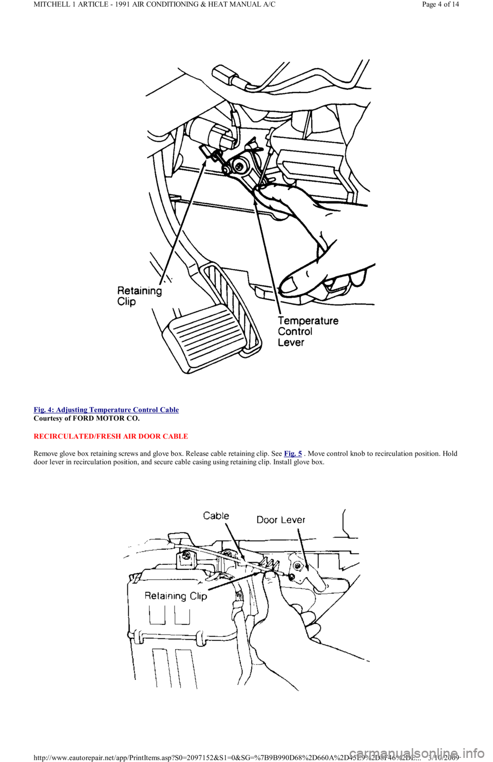
Temperature control cable is located at left base of evaporator housing. See Fig. 4
. Release cable retaining clip. Position temperature control
knob in maximum cool position. While holding thermostat cable in maximum cool position, secure cable casing using retaining clip.
Page 3 of 14 MITCHELL 1 ARTICLE - 1991 AIR CONDITIONING & HEAT MANUAL A/C
3/10/2009 http://www.eautorepair.net/app/PrintItems.asp?S0=2097152&S1=0&SG=%7B9B990D68%2D660A%2D45E9%2D8F46%2DE
...
Page 352 of 454
Fig. 4: Adjusting Temperature Control Cable
Courtesy of FORD MOTOR CO.
RECIRCULATED/FRESH AIR DOOR CABLE
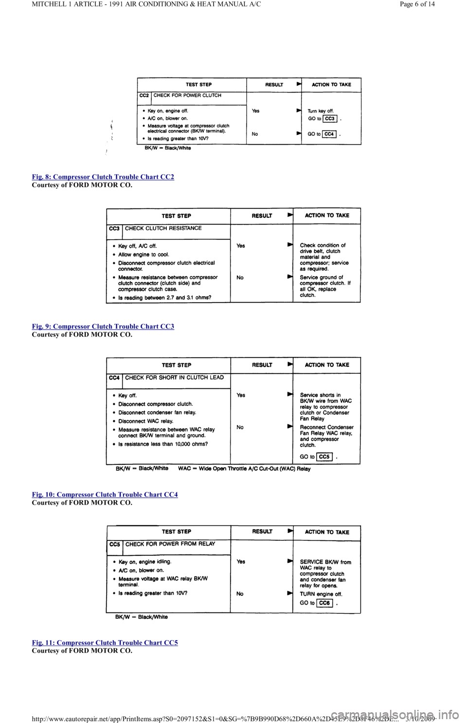
Remove glove box retaining screws and glove box. Release cable retaining clip. See Fig. 5
. Move control knob to recirculation position. Hold
door lever in recirculation position, and secure cable casing using retaining clip. Install glove box.
Page 4 of 14 MITCHELL 1 ARTICLE - 1991 AIR CONDITIONING & HEAT MANUAL A/C
3/10/2009 http://www.eautorepair.net/app/PrintItems.asp?S0=2097152&S1=0&SG=%7B9B990D68%2D660A%2D45E9%2D8F46%2DE
...
Page 353 of 454
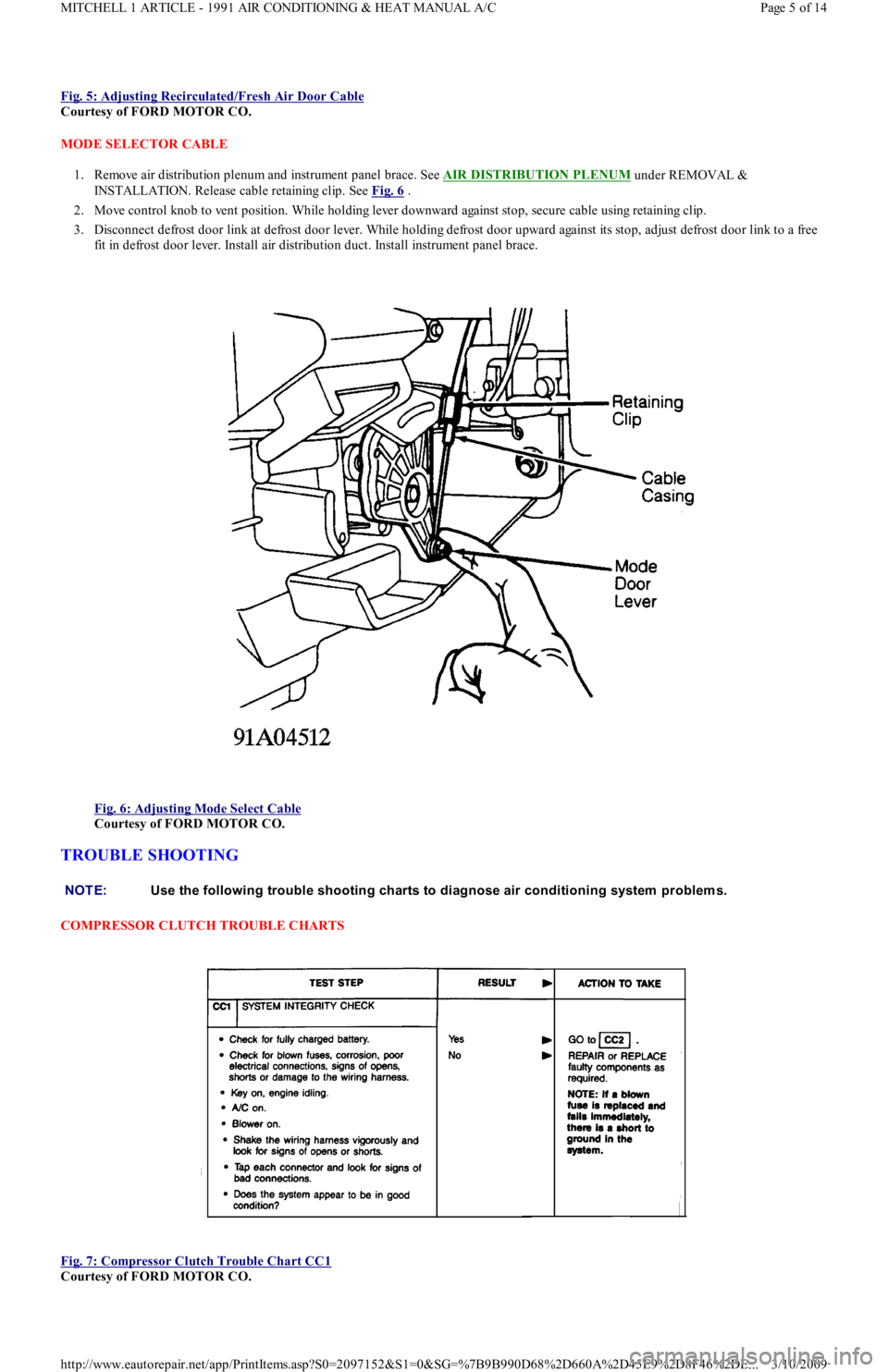
Fig. 5: Adjusting Recirculated/Fresh Air Door Cable
Courtesy of FORD MOTOR CO.
MODE SELECTOR CABLE
1. Remove air distribution plenum and instrument panel brace. See AIR DISTRIBUTION PLENUM
under REMOVAL &
INSTALLATION. Release cable retaining clip. See Fig. 6
.
2. Move control knob to vent position. While holding lever downward against stop, secure cable using retaining clip.
3. Disconnect defrost door link at defrost door lever. While holding defrost door upward against its stop, adjust defrost door link to a free
fit in defrost door lever. Install air distribution duct. Install instrument panel brace.
Fig. 6: Adjusting Mode Select Cable
Courtesy of FORD MOTOR CO.
TROUBLE SHOOTING
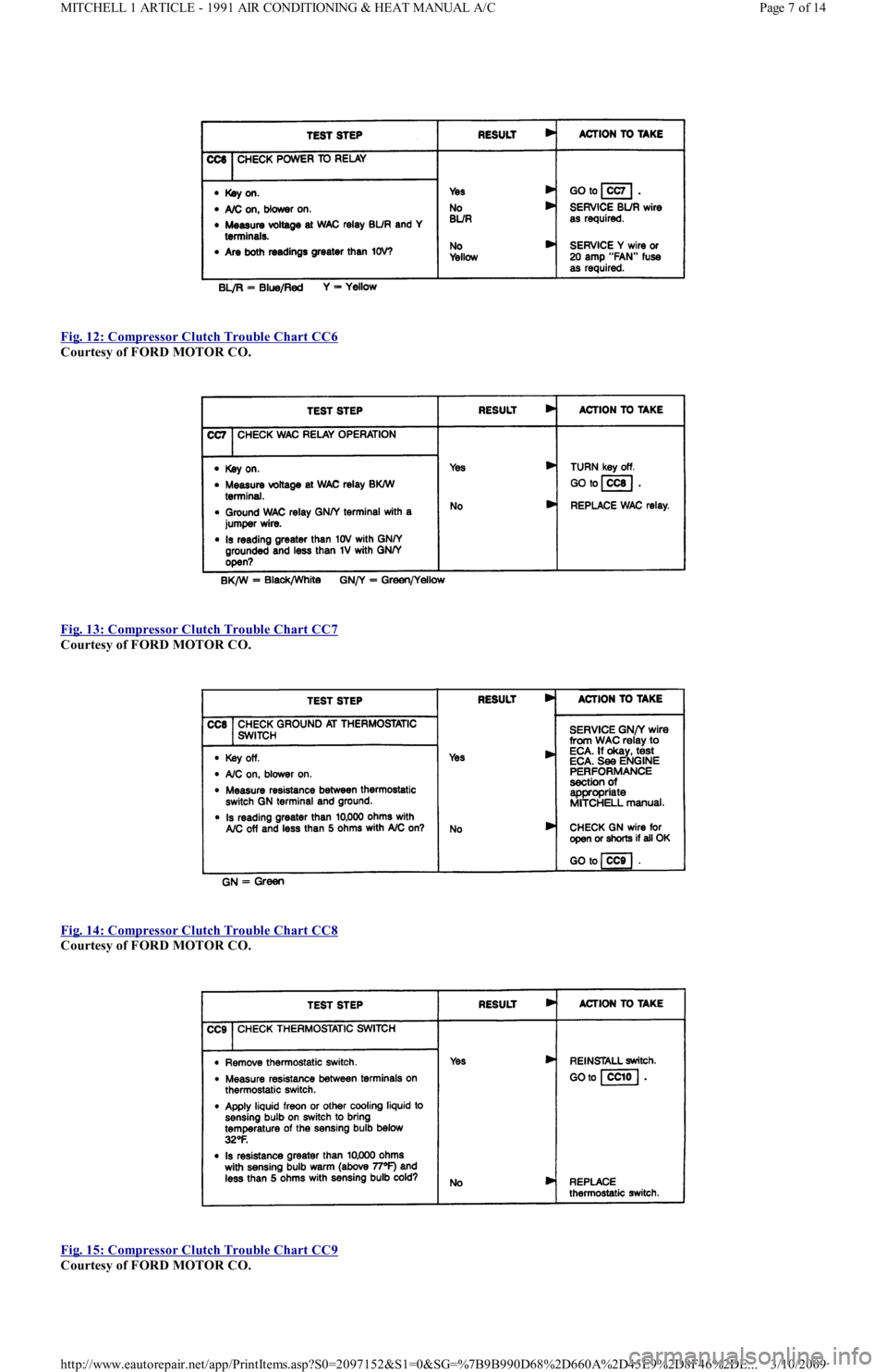
COMPRESSOR CLUTCH TROUBLE CHARTS
Fig. 7: Compressor Clutch Trouble Chart CC1
Courtesy of FORD MOTOR CO.
NOTE:Use the following trouble shooting charts to diagnose air conditioning system problem s.
Page 5 of 14 MITCHELL 1 ARTICLE - 1991 AIR CONDITIONING & HEAT MANUAL A/C
3/10/2009 http://www.eautorepair.net/app/PrintItems.asp?S0=2097152&S1=0&SG=%7B9B990D68%2D660A%2D45E9%2D8F46%2DE
...
Page 354 of 454
Fig. 8: Compressor Clutch Trouble Chart CC2
Courtesy of FORD MOTOR CO.
Fig. 9: Compressor Clutch Trouble Chart CC3
Courtesy of FORD MOTOR CO.
Fig. 10: Compressor Clutch Trouble Chart CC4
Courtesy of FORD MOTOR CO.
Fig. 11: Compressor Clutch Trouble Chart CC5
Courtesy of FORD MOTOR CO.
Page 6 of 14 MITCHELL 1 ARTICLE - 1991 AIR CONDITIONING & HEAT MANUAL A/C
3/10/2009 http://www.eautorepair.net/app/PrintItems.asp?S0=2097152&S1=0&SG=%7B9B990D68%2D660A%2D45E9%2D8F46%2DE
...
Page 355 of 454
Fig. 12: Compressor Clutch Trouble Chart CC6
Courtesy of FORD MOTOR CO.
Fig. 13: Compressor Clutch Trouble Chart CC7
Courtesy of FORD MOTOR CO.
Fig. 14: Compressor Clutch Trouble Chart CC8
Courtesy of FORD MOTOR CO.
Fig. 15: Compressor Clutch Trouble Chart CC9
Courtesy of FORD MOTOR CO.
Page 7 of 14 MITCHELL 1 ARTICLE - 1991 AIR CONDITIONING & HEAT MANUAL A/C
3/10/2009 http://www.eautorepair.net/app/PrintItems.asp?S0=2097152&S1=0&SG=%7B9B990D68%2D660A%2D45E9%2D8F46%2DE
...
Page 356 of 454
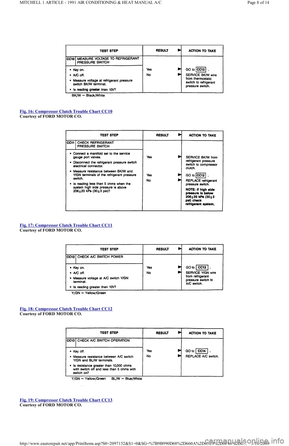
Fig. 16: Compressor Clutch Trouble Chart CC10
Courtesy of FORD MOTOR CO.
Fig. 17: Compressor Clutch Trouble Chart CC11
Courtesy of FORD MOTOR CO.
Fig. 18: Compressor Clutch Trouble Chart CC12
Courtesy of FORD MOTOR CO.
Fig. 19: Compressor Clutch Trouble Chart CC13
Courtesy of FORD MOTOR CO.
Page 8 of 14 MITCHELL 1 ARTICLE - 1991 AIR CONDITIONING & HEAT MANUAL A/C
3/10/2009 http://www.eautorepair.net/app/PrintItems.asp?S0=2097152&S1=0&SG=%7B9B990D68%2D660A%2D45E9%2D8F46%2DE
...
Page 357 of 454
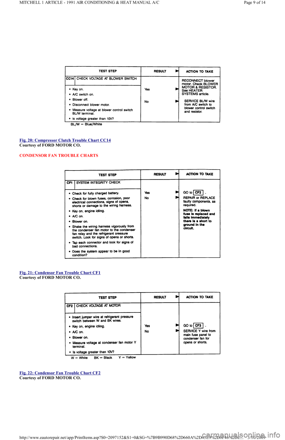
Fig. 20: Compressor Clutch Trouble Chart CC14
Courtesy of FORD MOTOR CO.
CONDENSOR FAN TROUBLE CHARTS
Fig. 21: Condensor Fan Trouble Chart CF1
Courtesy of FORD MOTOR CO.
Fig. 22: Condensor Fan Trouble Chart CF2
Courtesy of FORD MOTOR CO.
Page 9 of 14 MITCHELL 1 ARTICLE - 1991 AIR CONDITIONING & HEAT MANUAL A/C
3/10/2009 http://www.eautorepair.net/app/PrintItems.asp?S0=2097152&S1=0&SG=%7B9B990D68%2D660A%2D45E9%2D8F46%2DE
...