1990 VOLVO 240 heater
[x] Cancel search: heaterPage 7 of 143

Volvo 1990 240 Model
5 Instruments 10
6 Wiper/washer, tailgate window wiper/washer (wagon) 16
7 Starting (ignition) switch/steering wheel lock 14
8 Air louver 23
9 Radio location 25
10 Air louver 23
11 Glove box -
12 Air louver 23
13 Fuse box 81
14 Hood release handle 34
15 Horn -
16 Cigarette lighter 20
17 Rear window demister 18
18 Hazard warning flashers 18
19 Air conditioning (some models) 24
20 Seat belt reminder light 28
21 Heating and ventilation 22
22 Gear lever or gear selector 45, 46
23 Ash tray 20
24 Storage compartment -
25 Electrically-operated windows (certain models only) 21
26 Control for electrically operated side mirrors (certain models only)\
-
27 Parking brake 19
28 Electrically-operated window, right front door (certain models only)\
21
29 Seat belt release buttons 28
30 Seat heaters 19
31 Seat belt reminder light 28
32 Ash tray 20
The pages in this section provide a detailed description of the vehicle'\
s instruments and controls.
Note that some vehicles may be equipped differently, depending on model,\
special legal requirements,
etc. pg. 10 Instruments
file:///K|/ownersdocs/1990/1990_240/90240_01.htm (3 of 5)12/30/2006 8:\
25:01 AM
Page 14 of 143

Volvo 1990 240 Model
pg. 14 Starting (ignition) switch, Turn signals
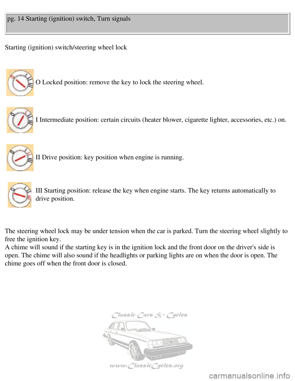
Starting (ignition) switch/steering wheel lock
O Locked position: remove the key to lock the steering wheel.
I Intermediate position: certain circuits (heater blower, cigarette lig\
hter, accessories, etc.) on.
II Drive position: key position when engine is running.
III Starting position: release the key when engine starts. The key retur\
ns automatically to
drive position.
The steering wheel lock may be under tension when the car is parked. Tur\
n the steering wheel slightly to
free the ignition key.
A chime will sound if the starting key is in the ignition lock and the f\
ront door on the driver's side is
open. The chime will also sound if the headlights or parking lights are \
on when the door is open. The
chime goes off when the front door is closed.
file:///K|/ownersdocs/1990/1990_240/90240_03.htm (1 of 7)12/30/2006 8:\
25:02 AM
Page 23 of 143

Volvo 1990 240 Model
Seat heaters
The front seats are equipped with electrically-heated backrests and seat\
cushions. The switches engage
the heating which then is thermostatically controlled. It switches on au\
tomatically when the temperature
drops below 60°F (15°C) and switches off at approx. 95°F (35\
°C). pg. 20 Cigarette lighter, Ash trays
Cigarette lighter
To operate, depress the knob fully. When the knob automatically releases\
, the cigarette lighter is ready
for use.
The starting (ignition) switch must be ON for the cigarette lighter to\
function.
file:///K|/ownersdocs/1990/1990_240/90240_04.htm (3 of 5)12/30/2006 8:\
25:02 AM
Page 84 of 143

Volvo 1990 240 Model
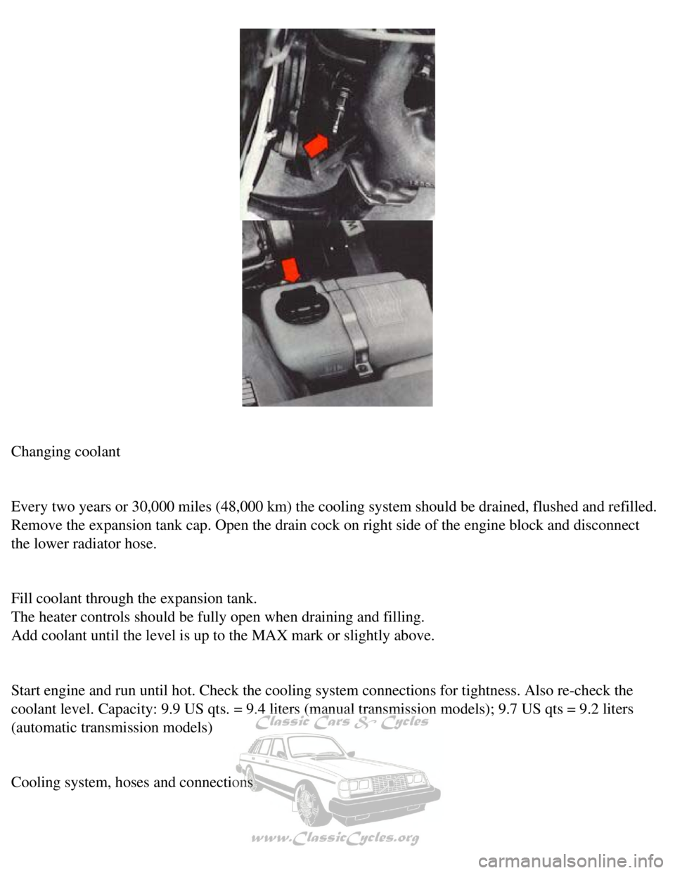
Changing coolant
Every two years or 30,000 miles (48,000 km) the cooling system should \
be drained, flushed and refilled.
Remove the expansion tank cap. Open the drain cock on right side of the \
engine block and disconnect
the lower radiator hose.
Fill coolant through the expansion tank.
The heater controls should be fully open when draining and filling.
Add coolant until the level is up to the MAX mark or slightly above.
Start engine and run until hot. Check the cooling system connections for\
tightness. Also re-check the
coolant level. Capacity: 9.9 US qts. = 9.4 liters (manual transmission \
models); 9.7 US qts = 9.2 liters
(automatic transmission models)
Cooling system, hoses and connections
file:///K|/ownersdocs/1990/1990_240/90240_13.htm (8 of 9)12/30/2006 8:\
25:08 AM
Page 86 of 143

Volvo 1990 240 Model
pg. 64 Service requirements
Engine Mechanical Components
Torque manifold nuts
The manifold nuts should be torqued at the 600-1,200 mile (1,000-2,000 \
km) inspection. A loose
manifold could alter air/fuel ratio and cause an increase in emission an\
d/or poor driveability.
Valves
The valve clearance should be checked every 30,000 miles (48,000 km). \
Vacuum fittings, hoses and connections
Unstable idle, misfiring or poor emission control is often caused by lea\
king vacuum hoses or
connections. Check hoses and connections on distributor vacuum unit, EGR\
valve (where applicable)
and connections on heater control servo systems and hydraulic brake serv\
o.
Exhaust Gas Recirculation (EGR)
This system operates by returning some of the exhaust gases to the engin\
e to be recombusted: since this
lowers the combustion temperature the amount of nitrogen oxides released\
into the atmosphere is
reduced.
The EGR valve should be cleaned at the 60,000 mile inspection and therea\
fter cleaned every 25,000
miles (40,000 km).
Timing belt
The timing belt tensioner should be adjusted at the 600-1,200 mile (1,0\
00-2,000 km) inspection.
file:///K|/ownersdocs/1990/1990_240/90240_14.htm (1 of 7)12/30/2006 8:\
25:08 AM
Page 100 of 143

Volvo 1990 240 Model
Cooling system
The risk of overheating is greatest, especially in hot weather, when:
- towing a trailer up steep inclines for prolonged periods at full throt\
tle, and at low engine rpm.
- idling for prolonged periods while the air conditioning system is in o\
peration.
- stopping the engine suddenly after high speed driving, so called after\
-boiling.
To avoid overheating. the following rules should be followed.
l Reduce speed and downshift when towing a trailer up long steep inclines.\
The risk of over heating can
be reduced by switching off the air conditioning system for a short whil\
e.
l Do not let the engine idle unnecessarily.
l Do not stop the engine immediately after high-speed driving, but allow t\
he engine to idle for 1/2 - 1
minute before switching off.
When the risk of overheating is imminent, or in the event of overheating\
, (the temperature gauge goes
repeatedly into, or stays continually in, the red section) the followin\
g precautions should be taken:
l Switch off the air conditioning system and switch the heater to full (m\
aximum) position.
l Stop the car and put the gear lever into neutral position-position N. Do\
not stop the engine!
l Increase the engine speed to approx. 2000 rpm (twice idling speed).
l Check the level of coolant in the expansion tank. Top-up, if necessary
pg. 75 Alternator, Jump starting
Electrical System cautions
When changing the battery or when carrying out work involving the electr\
ical system, the following
should be observed:
1 A battery connection to the wrong terminal will damage the diodes. Bef\
ore connections are made,
check the polarity of the battery with a voltmeter.
2 If booster batteries are used for starting, they must be properly conn\
ected to prevent the diodes from
being damaged. For correct connection, see "Jump starting".
3 The battery leads should be disconnected any time the battery is being\
charged.
file:///K|/ownersdocs/1990/1990_240/90240_15.htm (8 of 10)12/30/2006 8\
:25:09 AM
Page 111 of 143

Volvo 1990 240 Model
Remove screw holding the light assembly Lift it out to remove.
Replace the bulb.
Reinstall by first inserting the guides into one side, then press ir, th\
e light assembly and install the screw.
Bulb Power Socket
Engine compartment light 15 W S 8.5 - 8
Trunk light 15 W S 8.5 - 8
Instrument and heater control lighting
Due to the location of these bulbs their replacement should be carried o\
ut by a Volvo dealer. pg. 81 Fuses
Replacing fuses
The fuse box is positioned in front of the left front door pillar. When \
replacing fuses, check that the
correct amperage is used.
Never use fuses of higher amperage. unless specified by your Volvo deale\
r. If one fuse repeatedly fails,
take the car to your Volvo dealer for fault tracing.
A spare fuse kit is available from your Volvo dealer.
file:///K|/ownersdocs/1990/1990_240/90240_16.htm (9 of 10)12/30/2006 8\
:25:10 AM
Page 112 of 143

Volvo 1990 240 Model
Warning: Turn starting (ignition) switch OFF before replacing fuses. E\
xcessive heat may be created by
a short circuit. Care must be exercised while replacing blown fuses.
Some of the equipment listed below is optional
Refer to the fuse location chart at fuse box for fuses specific to your \
car.
1 Cigarette lighter, Power mirrors, Radio, Tailgate wiper/washer 8A
2 Windshield wiper/washer, Horn 16A
3 Heater blower 25A
4 Fuel feed (in-tank) pump, Lambda-sond heating element 8A
5 Turn signals, Back-up lights 16A
6 Main fuel pump relay 16A
7 Brake lights 8A
8 Central locking, Interior and glove compartment lights, Trunk and engi\
ne
compartment lights, Radio, Power antenna, Clock, Daytime running lights \
(Canada)* 8A
9 Hazard warning Flashers 8A
10 Power windows 16A
11 Heated rear window, 4th gear (automatic transmission) 16A
12 Air conditioning (with blower control), Power windows (relay),
Heated rear window (relay), Seat belt reminder, Cruise control 8A
13 Heated front seats, Daytime running lights - relay (Canada)* 16A
14 Rear fog lights 8A
15 Parking lights (left side), License plate light 8A
16 Parking lights (right side), Instruments and control panel lights, \
Shift indicator light 8A
Blade type fuse, serving LH-Jetronic fuel injection system. Located on t\
he left
wheel housing by the ignition coil 25A
* Note: Early production Canadian vehicles are not equipped with Daytime\
Running Lights.
Contents | Top of Page
file:///K|/ownersdocs/1990/1990_240/90240_16.htm (10 of 10)12/30/2006 \
8:25:10 AM