1990 VOLVO 240 air conditioning
[x] Cancel search: air conditioningPage 5 of 143
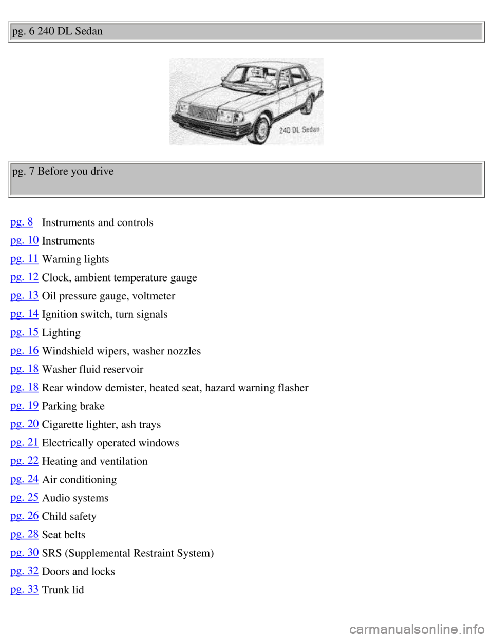
Volvo 1990 240 Model
pg. 6 240 DL Sedan
pg. 7 Before you drive
pg. 8Instruments and controls
pg. 10Instruments
pg. 11Warning lights
pg. 12Clock, ambient temperature gauge
pg. 13Oil pressure gauge, voltmeter
pg. 14Ignition switch, turn signals
pg. 15Lighting
pg. 16Windshield wipers, washer nozzles
pg. 18Washer fluid reservoir
pg. 18Rear window demister, heated seat, hazard warning flasher
pg. 19Parking brake
pg. 20Cigarette lighter, ash trays
pg. 21Electrically operated windows
pg. 22Heating and ventilation
pg. 24Air conditioning
pg. 25Audio systems
pg. 26Child safety
pg. 28Seat belts
pg. 30SRS (Supplemental Restraint System)
pg. 32Doors and locks
pg. 33Trunk lid
file:///K|/ownersdocs/1990/1990_240/90240_01.htm (1 of 5)12/30/2006 8:\
25:01 AM
Page 7 of 143

Volvo 1990 240 Model
5 Instruments 10
6 Wiper/washer, tailgate window wiper/washer (wagon) 16
7 Starting (ignition) switch/steering wheel lock 14
8 Air louver 23
9 Radio location 25
10 Air louver 23
11 Glove box -
12 Air louver 23
13 Fuse box 81
14 Hood release handle 34
15 Horn -
16 Cigarette lighter 20
17 Rear window demister 18
18 Hazard warning flashers 18
19 Air conditioning (some models) 24
20 Seat belt reminder light 28
21 Heating and ventilation 22
22 Gear lever or gear selector 45, 46
23 Ash tray 20
24 Storage compartment -
25 Electrically-operated windows (certain models only) 21
26 Control for electrically operated side mirrors (certain models only)\
-
27 Parking brake 19
28 Electrically-operated window, right front door (certain models only)\
21
29 Seat belt release buttons 28
30 Seat heaters 19
31 Seat belt reminder light 28
32 Ash tray 20
The pages in this section provide a detailed description of the vehicle'\
s instruments and controls.
Note that some vehicles may be equipped differently, depending on model,\
special legal requirements,
etc. pg. 10 Instruments
file:///K|/ownersdocs/1990/1990_240/90240_01.htm (3 of 5)12/30/2006 8:\
25:01 AM
Page 13 of 143
Volvo 1990 240 Model
The gauge pointer must not go down to the red
field while driving.
Do not continue to drive the car with the pointer in
the red zone.
Note: While idling with a hot engine the pointer
may go into the red field. This is not a cause for
concern providing the pointer rises to the normal
driving range again when you increase the engine
speed. should be within the black field.
Should the pointer point to the upper or lower red
field when driving, this may indicate some fault in
the electrical system.
Note: While idling with a hot engine (especially
with air conditioning ON), the pointer may
indicate low voltage. This is not a cause for
concern provided that the indicated voltage
increases when you increase engine speed.
Contents | Top of Page
file:///K|/ownersdocs/1990/1990_240/90240_02.htm (4 of 4)12/30/2006 8:\
25:02 AM
Page 26 of 143
Volvo 1990 240 Model
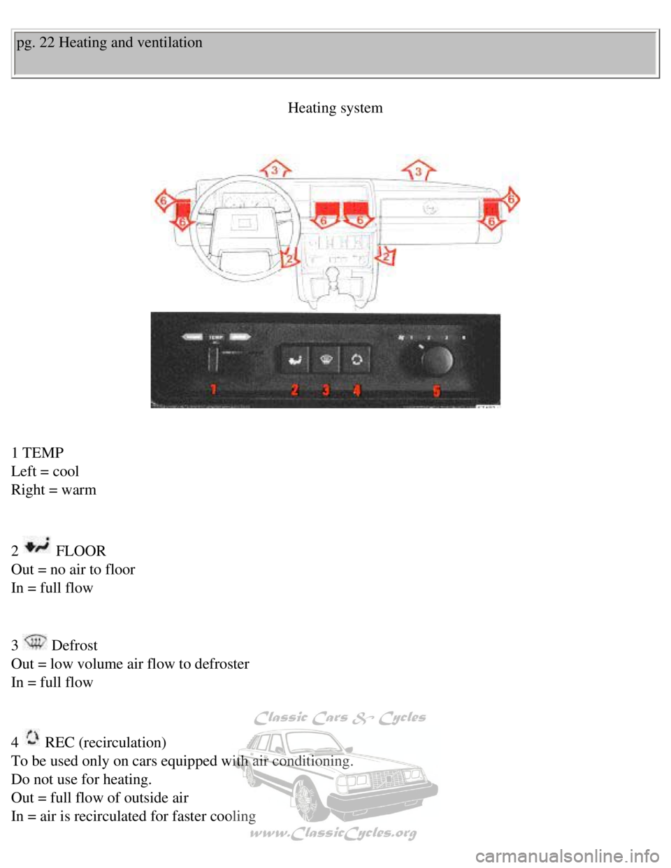
pg. 22 Heating and ventilation Heating system
1 TEMP
Left = cool
Right = warm
2
FLOOR
Out = no air to floor
In = full flow
3
Defrost
Out = low volume air flow to defroster
In = full flow
4
REC (recirculation)
To be used only on cars equipped with air conditioning.
Do not use for heating.
Out = full flow of outside air
In = air is recirculated for faster cooling
file:///K|/ownersdocs/1990/1990_240/90240_05.htm (1 of 6)12/30/2006 8:\
25:03 AM
Page 28 of 143
Volvo 1990 240 Model
If not using air conditioning, the recirculation feature should not be u\
sed in humid climates and at
temperatures above +23°F (-5°C).
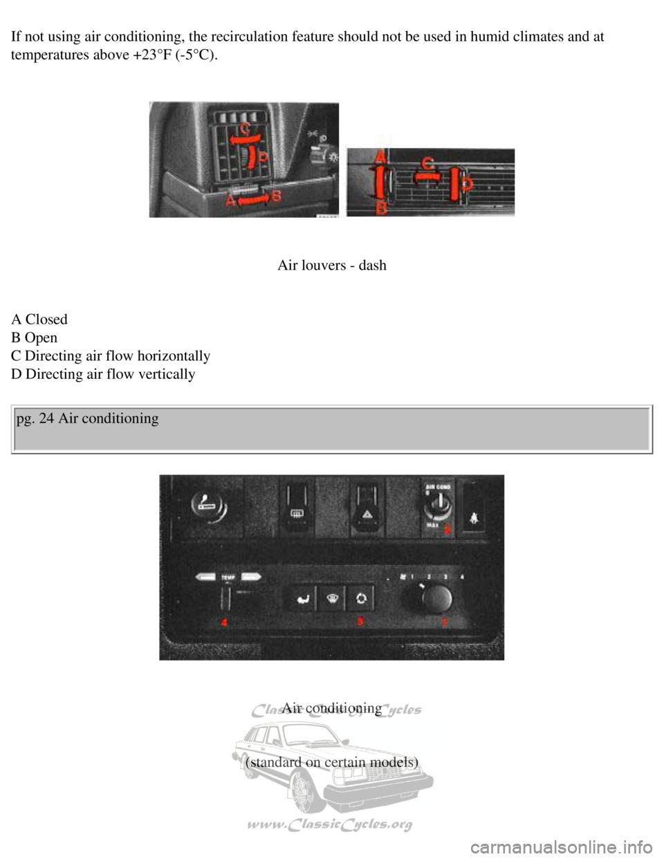
Air louvers - dash
A Closed
B Open
C Directing air flow horizontally
D Directing air flow vertically
pg. 24 Air conditioning
Air conditioning
(standard on certain models)
file:///K|/ownersdocs/1990/1990_240/90240_05.htm (3 of 6)12/30/2006 8:\
25:03 AM
Page 29 of 143
Volvo 1990 240 Model
How to use the air conditioner:
1
Fan
Position 4 for rapid cooling.
2 AIR COND
Start the air conditioning compressor by turning the control knob clockw\
ise toward MAX.
For rapid cooling, position the knob into the orange range beyond MAX. A\
fter desired temperature is
reached re-position the control knob into the blue range.
At cruising speeds, the knob should be kept within the blue range. If it\
remains in the orange range, icing
may occur resulting in decreased cooling capacity.
3
Recirculation
Push in for rapid cooling and during high humidity conditions.
4 TEMP
When using the air conditioner for cooling, the TEMP control should be s\
et to COOL position, fully left.
Use the AIR COND control to regulate the temperature.
To obtain rapid cooling, all windows must be closed and buttons
and out. Cool air will then be
discharged through the four dash outlets which should be fully open.
Note: For rapid removal of condensation from inside glass surfaces, the \
air conditioner can be
switched on even when not required for interior cooling. The air conditi\
oner will dehumidify the air
inside the vehicle.
Have your Volvo dealer check the system for correct operation yearly. Th\
e air conditioning system
should be operated periodically to ensure trouble-free performance year \
round.
pg. 25 Audio systems
Operating instructions
file:///K|/ownersdocs/1990/1990_240/90240_05.htm (4 of 6)12/30/2006 8:\
25:03 AM
Page 100 of 143
Volvo 1990 240 Model
Cooling system
The risk of overheating is greatest, especially in hot weather, when:
- towing a trailer up steep inclines for prolonged periods at full throt\
tle, and at low engine rpm.
- idling for prolonged periods while the air conditioning system is in o\
peration.
- stopping the engine suddenly after high speed driving, so called after\
-boiling.
To avoid overheating. the following rules should be followed.
l Reduce speed and downshift when towing a trailer up long steep inclines.\
The risk of over heating can
be reduced by switching off the air conditioning system for a short whil\
e.
l Do not let the engine idle unnecessarily.
l Do not stop the engine immediately after high-speed driving, but allow t\
he engine to idle for 1/2 - 1
minute before switching off.
When the risk of overheating is imminent, or in the event of overheating\
, (the temperature gauge goes
repeatedly into, or stays continually in, the red section) the followin\
g precautions should be taken:
l Switch off the air conditioning system and switch the heater to full (m\
aximum) position.
l Stop the car and put the gear lever into neutral position-position N. Do\
not stop the engine!
l Increase the engine speed to approx. 2000 rpm (twice idling speed).
l Check the level of coolant in the expansion tank. Top-up, if necessary
pg. 75 Alternator, Jump starting
Electrical System cautions
When changing the battery or when carrying out work involving the electr\
ical system, the following
should be observed:
1 A battery connection to the wrong terminal will damage the diodes. Bef\
ore connections are made,
check the polarity of the battery with a voltmeter.
2 If booster batteries are used for starting, they must be properly conn\
ected to prevent the diodes from
being damaged. For correct connection, see "Jump starting".
3 The battery leads should be disconnected any time the battery is being\
charged.
file:///K|/ownersdocs/1990/1990_240/90240_15.htm (8 of 10)12/30/2006 8\
:25:09 AM
Page 112 of 143

Volvo 1990 240 Model
Warning: Turn starting (ignition) switch OFF before replacing fuses. E\
xcessive heat may be created by
a short circuit. Care must be exercised while replacing blown fuses.
Some of the equipment listed below is optional
Refer to the fuse location chart at fuse box for fuses specific to your \
car.
1 Cigarette lighter, Power mirrors, Radio, Tailgate wiper/washer 8A
2 Windshield wiper/washer, Horn 16A
3 Heater blower 25A
4 Fuel feed (in-tank) pump, Lambda-sond heating element 8A
5 Turn signals, Back-up lights 16A
6 Main fuel pump relay 16A
7 Brake lights 8A
8 Central locking, Interior and glove compartment lights, Trunk and engi\
ne
compartment lights, Radio, Power antenna, Clock, Daytime running lights \
(Canada)* 8A
9 Hazard warning Flashers 8A
10 Power windows 16A
11 Heated rear window, 4th gear (automatic transmission) 16A
12 Air conditioning (with blower control), Power windows (relay),
Heated rear window (relay), Seat belt reminder, Cruise control 8A
13 Heated front seats, Daytime running lights - relay (Canada)* 16A
14 Rear fog lights 8A
15 Parking lights (left side), License plate light 8A
16 Parking lights (right side), Instruments and control panel lights, \
Shift indicator light 8A
Blade type fuse, serving LH-Jetronic fuel injection system. Located on t\
he left
wheel housing by the ignition coil 25A
* Note: Early production Canadian vehicles are not equipped with Daytime\
Running Lights.
Contents | Top of Page
file:///K|/ownersdocs/1990/1990_240/90240_16.htm (10 of 10)12/30/2006 \
8:25:10 AM