Page 89 of 143
Volvo 1990 240 Model
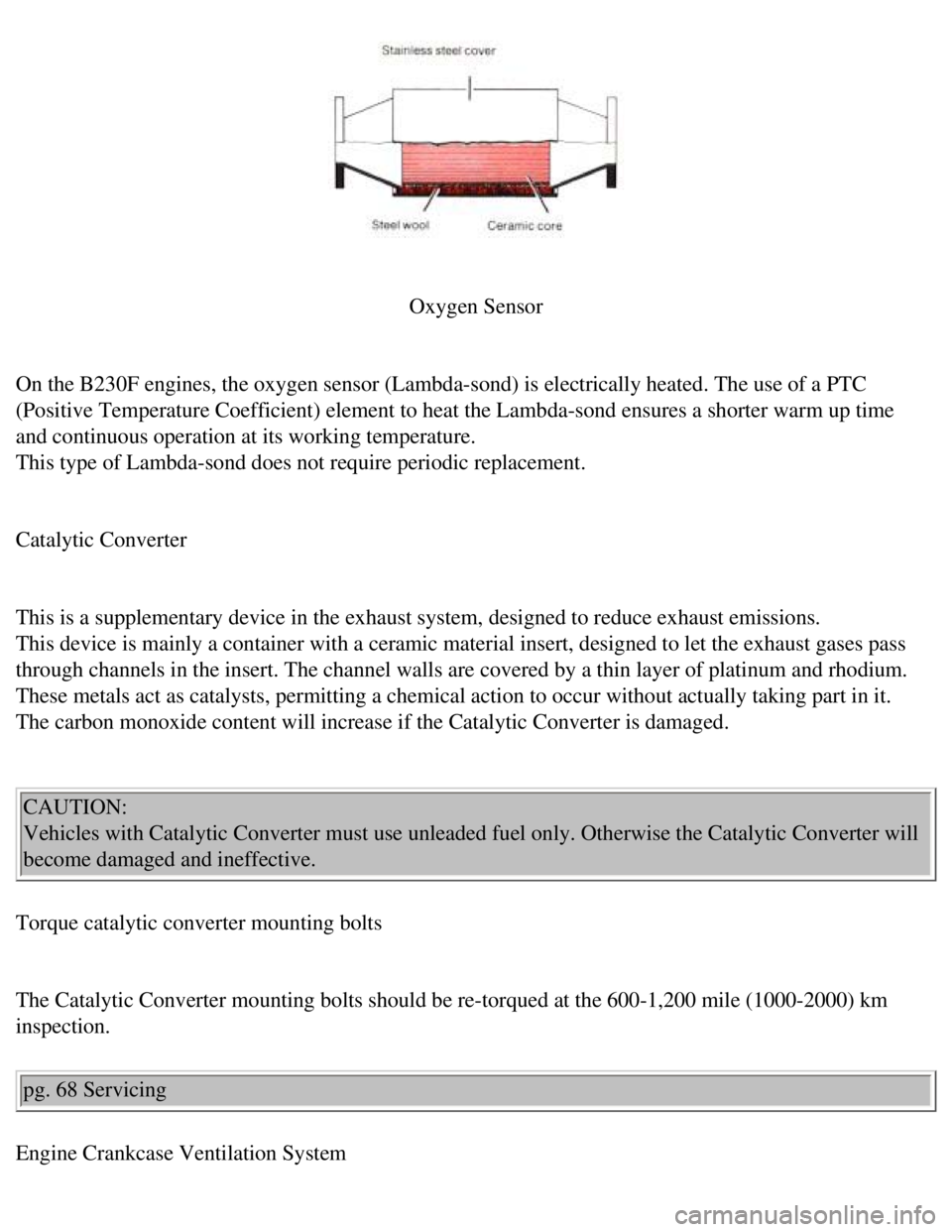
Oxygen Sensor
On the B230F engines, the oxygen sensor (Lambda-sond) is electrically \
heated. The use of a PTC
(Positive Temperature Coefficient) element to heat the Lambda-sond ens\
ures a shorter warm up time
and continuous operation at its working temperature.
This type of Lambda-sond does not require periodic replacement.
Catalytic Converter
This is a supplementary device in the exhaust system, designed to reduce\
exhaust emissions.
This device is mainly a container with a ceramic material insert, design\
ed to let the exhaust gases pass
through channels in the insert. The channel walls are covered by a thin \
layer of platinum and rhodium.
These metals act as catalysts, permitting a chemical action to occur wit\
hout actually taking part in it.
The carbon monoxide content will increase if the Catalytic Converter is \
damaged.
CAUTION:
Vehicles with Catalytic Converter must use unleaded fuel only. Otherwise\
the Catalytic Converter will
become damaged and ineffective.
Torque catalytic converter mounting bolts
The Catalytic Converter mounting bolts should be re-torqued at the 600-1\
,200 mile (1000-2000) km
inspection.
pg. 68 Servicing
Engine Crankcase Ventilation System
file:///K|/ownersdocs/1990/1990_240/90240_14.htm (4 of 7)12/30/2006 8:\
25:08 AM
Page 90 of 143
Volvo 1990 240 Model
Crankcase ventilation
The engine is provided with positive crankcase ventilation (PCV) which\
prevents crankcase gases from
being released into the atmosphere. Instead, the crankcase gases are adm\
itted to the intake manifold and
cylinders.
B230F
1. PCV nipple
2. Flame
Guard
3. Oil trap
PCV system, B230F engine
The PCV nipple in the intake manifold should be cleaned after 60,000 mil\
es (96,000 km). pg. 69 Servicing
Engine Evaporative Emissions
file:///K|/ownersdocs/1990/1990_240/90240_14.htm (5 of 7)12/30/2006 8:\
25:08 AM
Page 91 of 143

Volvo 1990 240 Model
Evaporative control systems
Vehicles intended for the North American market are equipped with a fuel\
vapor evaporative control
system, which prevents gasoline fumes from being released into the atmos\
phere.
The system is comprised of an expansion chamber in the fuel tank, a roll\
-over valve on the cross
member in front of the fuel tank, and a charcoal canister with built-in \
vacuum valve. The components
are interconnected by hoses which channel fuel vapor from the gas tank t\
o the charcoal filter where they
are stored until the engine is started and then drawn into the engine fu\
el induction system.
Engine Ignition
Change spark plugs
The spark plugs should be changed every 30,000 miles (48,000 km).
However, prolonged city driving or fast highway driving may necessitate \
changing spark plugs after
10,000 miles (16,000 km) of driving. When installing new plugs, be sur\
e to fit the right type and use the
correct torque, see "Specifications".
When changing the spark plugs, check that the suppressor connectors are \
in good condition. Cracked or
damaged connectors should be replaced.
When changing spark plugs, clean the cables and cable terminals, also th\
e rubber seals. If the car is
driven on roads where salt is used during the winter, coat the cables wi\
th silicone.
file:///K|/ownersdocs/1990/1990_240/90240_14.htm (6 of 7)12/30/2006 8:\
25:08 AM
Page 92 of 143
Volvo 1990 240 Model
WARNING!
The ignition system operates at very high voltages. Special safety preca\
utions must be followed to
prevent injury:
Always turn the ignition off when:
l connecting engine test and diagnostic equipment to the vehicle (timing \
light, tach-dwell tester,
ignition oscilloscope, etc.).
l Replacing ignition components e.g. plugs, coil, distributor, high-tensio\
n leads, etc.
Contents | Top of Page
file:///K|/ownersdocs/1990/1990_240/90240_14.htm (7 of 7)12/30/2006 8:\
25:08 AM
Page 94 of 143
Volvo 1990 240 Model
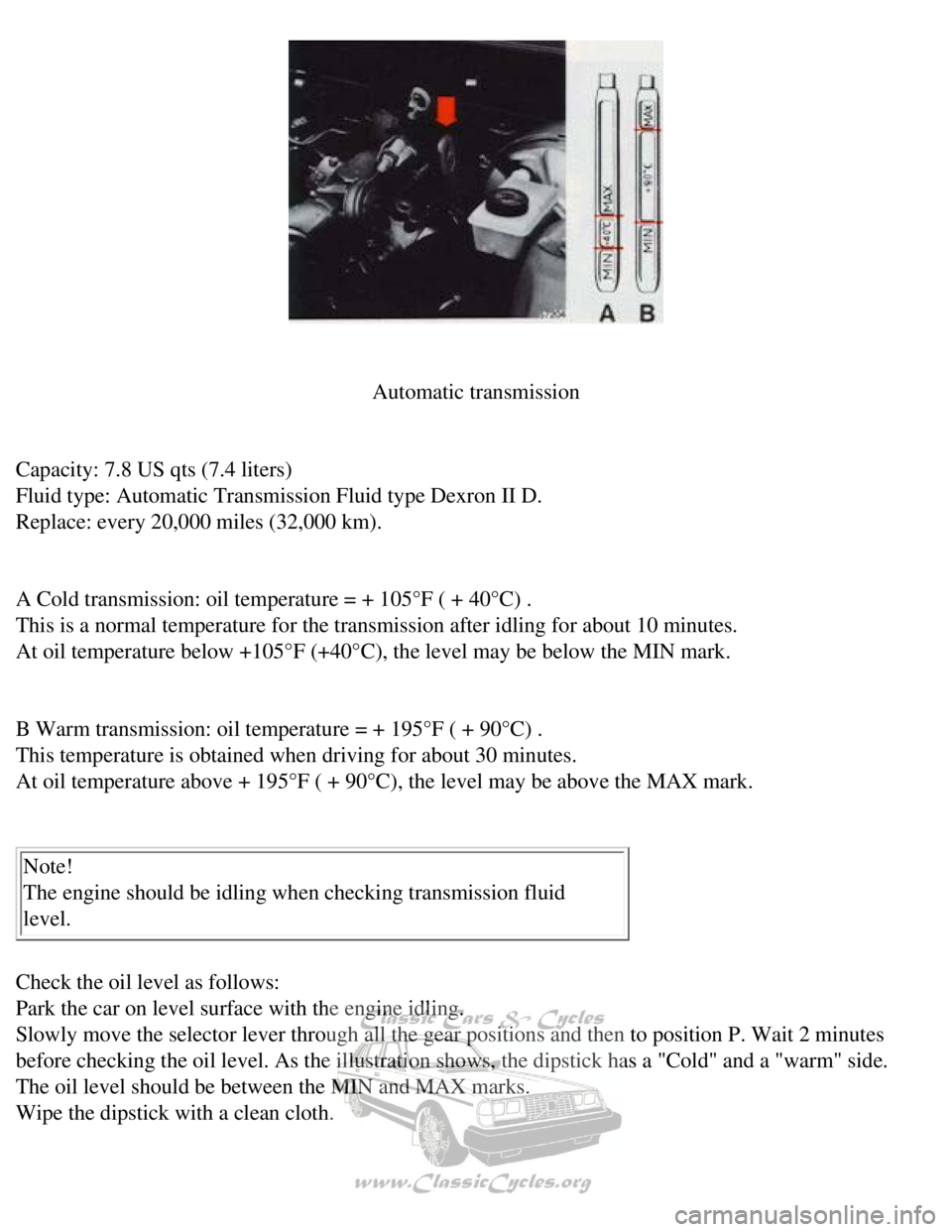
Automatic transmission
Capacity: 7.8 US qts (7.4 liters)
Fluid type: Automatic Transmission Fluid type Dexron II D.
Replace: every 20,000 miles (32,000 km).
A Cold transmission: oil temperature = + 105°F ( + 40°C) .
This is a normal temperature for the transmission after idling for about\
10 minutes.
At oil temperature below +105°F (+40°C), the level may be below \
the MIN mark.
B Warm transmission: oil temperature = + 195°F ( + 90°C) .
This temperature is obtained when driving for about 30 minutes.
At oil temperature above + 195°F ( + 90°C), the level may be abo\
ve the MAX mark.
Note!
The engine should be idling when checking transmission fluid
level.
Check the oil level as follows:
Park the car on level surface with the engine idling.
Slowly move the selector lever through all the gear positions and then t\
o position P. Wait 2 minutes
before checking the oil level. As the illustration shows, the dipstick h\
as a "Cold" and a "warm" side.
The oil level should be between the MIN and MAX marks.
Wipe the dipstick with a clean cloth.
file:///K|/ownersdocs/1990/1990_240/90240_15.htm (2 of 10)12/30/2006 8\
:25:09 AM
Page 99 of 143
Volvo 1990 240 Model
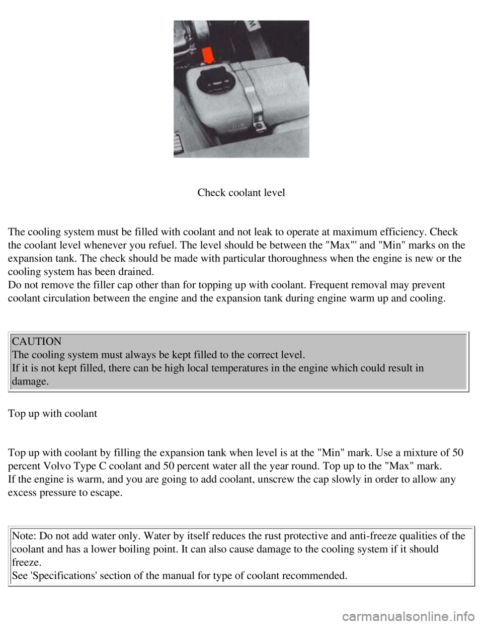
Check coolant level
The cooling system must be filled with coolant and not leak to operate a\
t maximum efficiency. Check
the coolant level whenever you refuel. The level should be between the "\
Max"' and "Min" marks on the
expansion tank. The check should be made with particular thoroughness wh\
en the engine is new or the
cooling system has been drained.
Do not remove the filler cap other than for topping up with coolant. Fre\
quent removal may prevent
coolant circulation between the engine and the expansion tank during eng\
ine warm up and cooling.
CAUTION
The cooling system must always be kept filled to the correct level.
If it is not kept filled, there can be high local temperatures in the en\
gine which could result in
damage.
Top up with coolant
Top up with coolant by filling the expansion tank when level is at the "\
Min" mark. Use a mixture of 50
percent Volvo Type C coolant and 50 percent water all the year round. To\
p up to the "Max" mark.
If the engine is warm, and you are going to add coolant, unscrew the cap\
slowly in order to allow any
excess pressure to escape.
Note: Do not add water only. Water by itself reduces the rust protective\
and anti-freeze qualities of the
coolant and has a lower boiling point. It can also cause damage to the c\
ooling system if it should
freeze.
See 'Specifications' section of the manual for type of coolant recommend\
ed.
file:///K|/ownersdocs/1990/1990_240/90240_15.htm (7 of 10)12/30/2006 8\
:25:09 AM
Page 100 of 143
Volvo 1990 240 Model
Cooling system
The risk of overheating is greatest, especially in hot weather, when:
- towing a trailer up steep inclines for prolonged periods at full throt\
tle, and at low engine rpm.
- idling for prolonged periods while the air conditioning system is in o\
peration.
- stopping the engine suddenly after high speed driving, so called after\
-boiling.
To avoid overheating. the following rules should be followed.
l Reduce speed and downshift when towing a trailer up long steep inclines.\
The risk of over heating can
be reduced by switching off the air conditioning system for a short whil\
e.
l Do not let the engine idle unnecessarily.
l Do not stop the engine immediately after high-speed driving, but allow t\
he engine to idle for 1/2 - 1
minute before switching off.
When the risk of overheating is imminent, or in the event of overheating\
, (the temperature gauge goes
repeatedly into, or stays continually in, the red section) the followin\
g precautions should be taken:
l Switch off the air conditioning system and switch the heater to full (m\
aximum) position.
l Stop the car and put the gear lever into neutral position-position N. Do\
not stop the engine!
l Increase the engine speed to approx. 2000 rpm (twice idling speed).
l Check the level of coolant in the expansion tank. Top-up, if necessary
pg. 75 Alternator, Jump starting
Electrical System cautions
When changing the battery or when carrying out work involving the electr\
ical system, the following
should be observed:
1 A battery connection to the wrong terminal will damage the diodes. Bef\
ore connections are made,
check the polarity of the battery with a voltmeter.
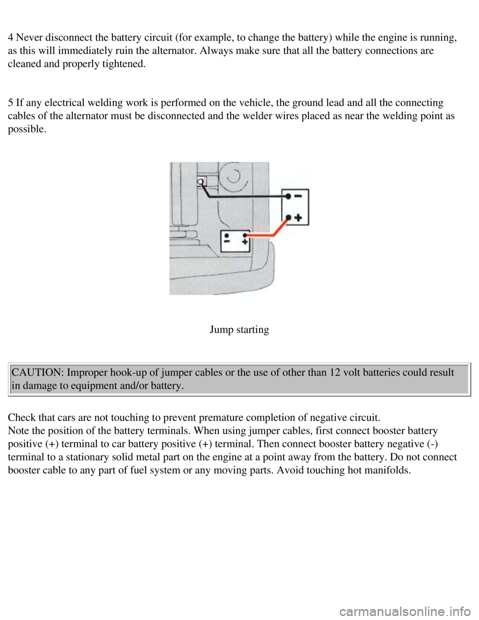
2 If booster batteries are used for starting, they must be properly conn\
ected to prevent the diodes from
being damaged. For correct connection, see "Jump starting".
3 The battery leads should be disconnected any time the battery is being\
charged.
file:///K|/ownersdocs/1990/1990_240/90240_15.htm (8 of 10)12/30/2006 8\
:25:09 AM
Page 101 of 143
Volvo 1990 240 Model
4 Never disconnect the battery circuit (for example, to change the batt\
ery) while the engine is running,
as this will immediately ruin the alternator. Always make sure that all \
the battery connections are
cleaned and properly tightened.
5 If any electrical welding work is performed on the vehicle, the ground\
lead and all the connecting
cables of the alternator must be disconnected and the welder wires place\
d as near the welding point as
possible.
Jump starting
CAUTION: Improper hook-up of jumper cables or the use of other than 12 v\
olt batteries could result
in damage to equipment and/or battery.
Check that cars are not touching to prevent premature completion of nega\
tive circuit.
Note the position of the battery terminals. When using jumper cables, fi\
rst connect booster battery
positive (+) terminal to car battery positive (+) terminal. Then con\
nect booster battery negative (-)
terminal to a stationary solid metal part on the engine at a point away \
from the battery. Do not connect
booster cable to any part of fuel system or any moving parts. Avoid touc\
hing hot manifolds.
file:///K|/ownersdocs/1990/1990_240/90240_15.htm (9 of 10)12/30/2006 8\
:25:09 AM