1990 VOLKSWAGEN CORRADO light
[x] Cancel search: lightPage 327 of 906

A/C COMPRESSOR SERVICING
Article Text
1990 Volkswagen Corrado
For Volkswagen Technical Site: http://vw.belcom.ru
Copyright © 1998 Mitchell Repair Information Company, LLC
Thursday, March 23, 2000 09:41PM
ARTICLE BEGINNING
1990 AIR CONDITIONING & HEAT
Compressor Service
* PLEASE READ THIS FIRST *
CAUTION: When discharging air conditioning system, use only approved
refrigerant recovery/recycling equipment. Make every attempt
to avoid discharging refrigerant into the atmosphere.
ISOLATING COMPRESSOR
NOTE: Only compressors with stem-type service valves can be
isolated.
1) Connect service gauge set to the compressor service valves
and open compressor valves slightly (turn in clockwise). Start engine
and operate air conditioning. Slowly turn compressor suction valve
clockwise toward closed (front-seated) position.
2) When suction pressure is reduced to zero or less, turn off
engine and compressor and quickly turn suction valve stem in to full
front-seated position. Suction pressure should be slightly above zero.
Turn discharge valve into front-seated position.
3) To check oil level, slowly open compressor crankcase plug
to relieve any remaining pressure. After oil level is corrected, cap
service gauge ports on both valves. Back-seat suction service valve to
allow refrigerant to enter compressor. Open discharge valve halfway.
4) Loosen discharge service valve cap, allowing refrigerant
pressure to force air out of compressor. Back-seat service valve and
tighten cap. Compressor is now ready for operation.
REFRIGERANT OIL
Only new, pure, moisture-free refrigerant oil should be used
in the air conditioning system. This oil is highly refined and
dehydrated to a point where moisture content is less than 10 parts per
million. The oil container must be tightly closed at all times when
not in use, or moisture will be absorbed into the refrigerant oil from
the air.
DISCHARGING SYSTEM PRECAUTIONS
CAUTION: When discharging air conditioning system, use only approved
refrigerant recovery/recycling equipment. Make every attempt
to avoid discharging refrigerant into the atmosphere.
If compressor has stem-type service valves, it can be
isolated and removed without discharging entire system. Otherwise,
discharge system completely using approved refrigerant
Page 330 of 906

A/C COMPRESSOR SERVICING
Article Text (p. 4)
1990 Volkswagen Corrado
For Volkswagen Technical Site: http://vw.belcom.ru
Copyright © 1998 Mitchell Repair Information Company, LLC
Thursday, March 23, 2000 09:41PM
Seal Seat Remover/Installer (64 5 030), remove seal seat.
2) Using Seal Remover/Installer (64 5 040), remove shaft seal
by turning seal slightly clockwise to disengage tangs and pull out
shaft seal. Remove "O" ring seal.
3) Coat new "O" ring seal with refrigerant oil and install.
Coat new shaft seal with refrigerant oil and install shaft seal on
Seal Remover/Installer (64 5 040). Ensure alignment of shaft seal and
shaft machine surfaces. Insert shaft seal and turn slightly
counterclockwise to secure on shaft.
4) Using sleeve from Seal Seat Remover/Installer (64 5 030),
push seal seat into compressor and install circlip. Install shaft key
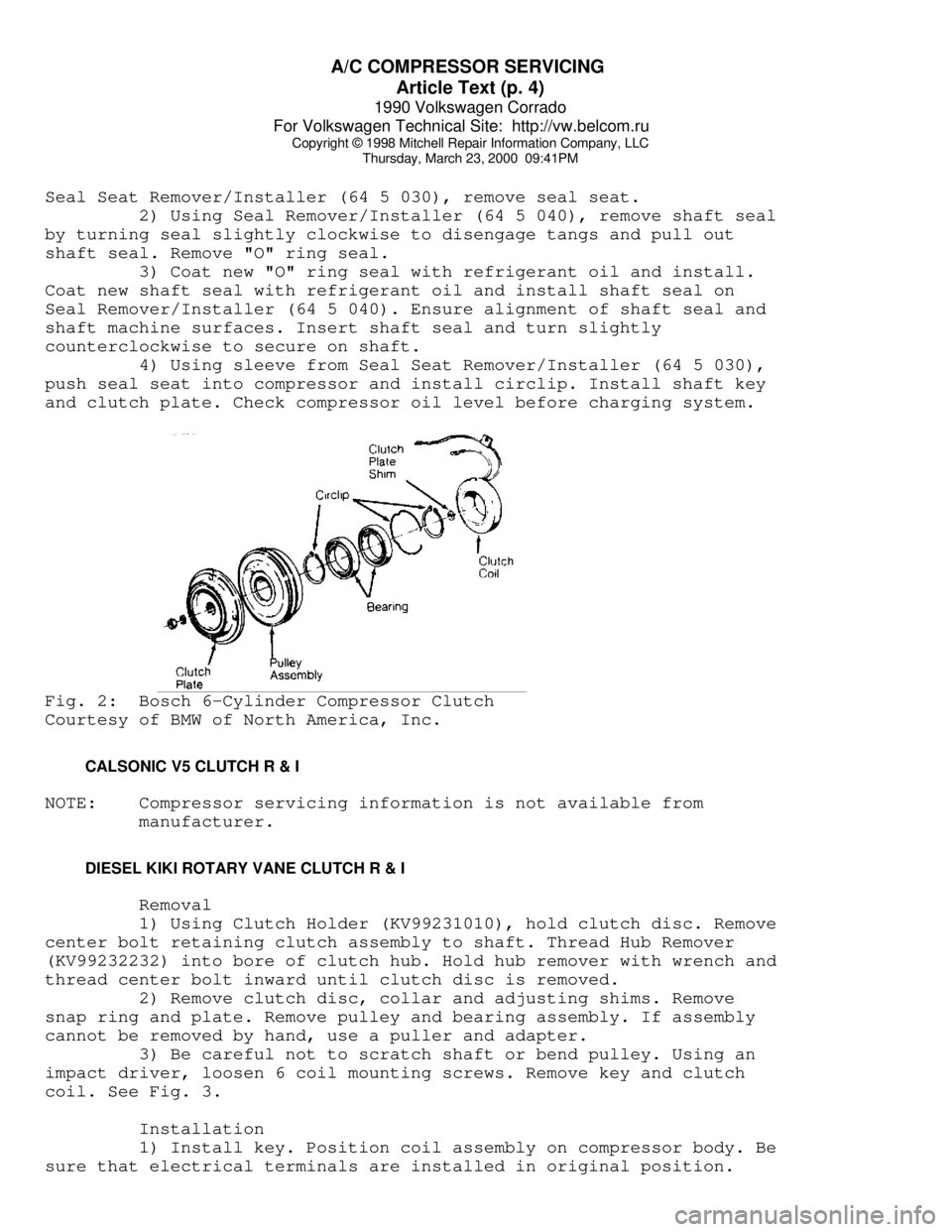
and clutch plate. Check compressor oil level before charging system.Fig. 2: Bosch 6-Cylinder Compressor Clutch
Courtesy of BMW of North America, Inc.
CALSONIC V5 CLUTCH R & I
NOTE: Compressor servicing information is not available from
manufacturer.
DIESEL KIKI ROTARY VANE CLUTCH R & I
Removal
1) Using Clutch Holder (KV99231010), hold clutch disc. Remove
center bolt retaining clutch assembly to shaft. Thread Hub Remover
(KV99232232) into bore of clutch hub. Hold hub remover with wrench and
thread center bolt inward until clutch disc is removed.
2) Remove clutch disc, collar and adjusting shims. Remove
snap ring and plate. Remove pulley and bearing assembly. If assembly
cannot be removed by hand, use a puller and adapter.
3) Be careful not to scratch shaft or bend pulley. Using an
impact driver, loosen 6 coil mounting screws. Remove key and clutch
coil. See Fig. 3.
Installation
1) Install key. Position coil assembly on compressor body. Be
sure that electrical terminals are installed in original position.
Page 333 of 906

A/C COMPRESSOR SERVICING
Article Text (p. 7)
1990 Volkswagen Corrado
For Volkswagen Technical Site: http://vw.belcom.ru
Copyright © 1998 Mitchell Repair Information Company, LLC
Thursday, March 23, 2000 09:41PM
Removal
1) Clamp Holding Fixture (J-25008-A) in a vise and attach
compressor to holding fixture with thumb screws. Use Clutch Hub Holder
(J-33027) to hold clutch. Remove shaft nut using Shaft Nut Socket (J-
9399).
2) Thread Clutch Plate and Hub Assembly Remover (J-33013-B)
into hub. Hold body of remover with a wrench and turn center screw
into remover body to remove clutch plate and hub assembly. Remove
shaft key and retain for assembly. See Fig. 5.
NOTE: DO NOT drive or pound on clutch hub or shaft.
Installation
1) Install shaft key into hub key groove. Allow key to
project approximately 1/8" out of key way. Shaft key is curved
slightly to provide an interference fit in hub key groove.
2) Ensure frictional surface of clutch plate and clutch rotor
are clean before installing clutch plate and hub assembly. Align shaft
key with shaft key way and place clutch plate and hub assembly onto
compressor shaft.
3) Hold hex portion of Installer (J-9480-B) with a wrench.
Tighten center screw to press hub into shaft until there is .020-.040"
(.5-1.0 mm) air gap between frictional plate and clutch rotor.
4) Install new shaft nut with small diameter boss of nut
against crankshaft shoulder. Use Thin Wall Socket (J-9399) and Clutch
Hub Holder (J-25030). Tighten shaft nut to 10 ft. lbs. (14 N.m). Spin
pulley rotor by hand to ensure rotor is not rubbing on clutch drive
plate.
HARRISON R4 4-CYL SHAFT SEAL R & I
Removal
1) Clamp Holding Fixture (J-25008-A) in a vise and attach
compressor to holding fixture with thumb screws. Use Clutch Hub Holder
(J-33027) to hold clutch. Remove shaft nut using Shaft Nut Socket (J-
9399).
2) Thread Clutch Plate and Hub Assembly Remover (J-33013-B)
into hub. Hold body of remover with a wrench and turn center screw
into remover body to remove clutch plate and hub assembly. Remove
clutch plate and shaft key. Pry out dust seal (if equipped). Remove
seal seat snap ring. Thoroughly clean compressor neck area and "O"
ring groove surrounding shaft. Any dirt or foreign material may cause
compressor damage.
3) Use Seal Remover/Installer (J23128-A), remove seal with a
twisting motion. Use "O" Ring Remover (J-9553-01) to remove "O" ring.
Installation
1) Coat new shaft seal with refrigerant oil and install shaft
seal on remover/installer. Align compressor shaft machined surface
with shaft seal and install. Turn remover/installer slightly
counterclockwise to secure shaft seal tangs.
2) Using Seal Installer (J-33011), install "O" ring and coat
Page 334 of 906

A/C COMPRESSOR SERVICING
Article Text (p. 8)
1990 Volkswagen Corrado
For Volkswagen Technical Site: http://vw.belcom.ru
Copyright © 1998 Mitchell Repair Information Company, LLC
Thursday, March 23, 2000 09:41PM
with refrigerant oil. Coat seal seat with refrigerant oil and install
using seal seat remover/installer. Install snap ring. Install dust
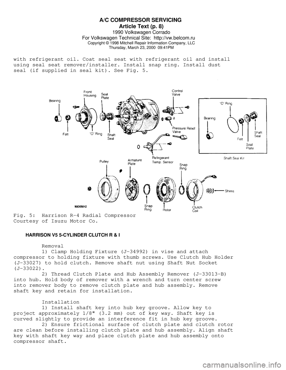
seal (if supplied in seal kit). See Fig. 5.Fig. 5: Harrison R-4 Radial Compressor
Courtesy of Isuzu Motor Co.
HARRISON V5 5-CYLINDER CLUTCH R & I
Removal
1) Clamp Holding Fixture (J-34992) in vise and attach
compressor to holding fixture with thumb screws. Use Clutch Hub Holder
(J-33027) to hold clutch. Remove shaft nut using Shaft Nut Socket
(J-33022).
2) Thread Clutch Plate and Hub Assembly Remover (J-33013-B)
into hub. Hold body of remover with a wrench and turn center screw
into remover body to remove clutch plate and hub assembly. Remove
shaft key and retain for installation.
Installation
1) Install shaft key into hub key groove. Allow key to
project approximately 1/8" (3.2 mm) out of key way. Shaft key is
curved slightly to provide an interference fit in hub key groove.
2) Ensure frictional surface of clutch plate and clutch rotor
are clean before installing clutch plate and hub assembly. Align shaft
key with shaft key way and place clutch plate and hub assembly onto
compressor shaft.
Page 340 of 906

A/C COMPRESSOR SERVICING
Article Text (p. 14)
1990 Volkswagen Corrado
For Volkswagen Technical Site: http://vw.belcom.ru
Copyright © 1998 Mitchell Repair Information Company, LLC
Thursday, March 23, 2000 09:41PM
ring and carbon seal contact surface of shaft seal seat for damage.
Make sure that "O" ring contact surface on front cover is not damaged.
Make sure refrigerant oil is applied to oil seal in shaft seal seat.
Installation
1) To install, reverse removal procedure. Ensure shaft seal
contact surface is free of dirt. Lubricate with refrigerant oil. Cap
end of compressor shaft.
2) Using Guard (KV994C1143), insert shaft seal. Be sure shaft
seal case is aligned with shaft. Apply force to turn seal to left and
right. Ensure shaft seal seats properly in shaft cut-out.
3) Fit "O" ring to outside groove of shaft seal seat. Ensure
"O" ring seats properly. Apply refrigerant oil on contact surfaces and
around shaft seal seat. Lightly coat surface of shaft with refrigerant
oil.
4) Install key on compressor shaft. Using snap ring pliers,
compress retainer ring and fit retainer ring into front cover. Seat
retainer ring firmly in groove. Thoroughly wipe grease or oil from
shaft surface.
5) Connect Installer (KV99412329) to shaft of compressor, and
turn shaft 5 or 6 times in a clockwise direction to seat seal. See
REFRIGERANT OIL & R-12 SPECIFICATIONS chart in this section for system
capacities.
MATSUSHITA ROTARY VANE CLUTCH R & I
Removal & Installation
1) Insert two 5 mm bolts into threaded holes in armature.
Using a screwdriver as lever in between bolts, remove center bolt.
remove armature and shim from shaft.
2) Remove snap ring. Using a puller, remove pulley.
Disconnect electrical leads from field coil. Remove 3 field coil
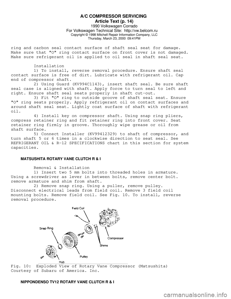
mounting bolts. Remove field coil. See Fig. 10. To install, reverse
removal procedure.Fig. 10: Exploded View of Rotary Vane Compressor (Matsushita)
Courtesy of Subaru of America. Inc.
NIPPONDENSO TV12 ROTARY VANE CLUTCH R & I
Page 345 of 906

A/C COMPRESSOR SERVICING
Article Text (p. 19)
1990 Volkswagen Corrado
For Volkswagen Technical Site: http://vw.belcom.ru
Copyright © 1998 Mitchell Repair Information Company, LLC
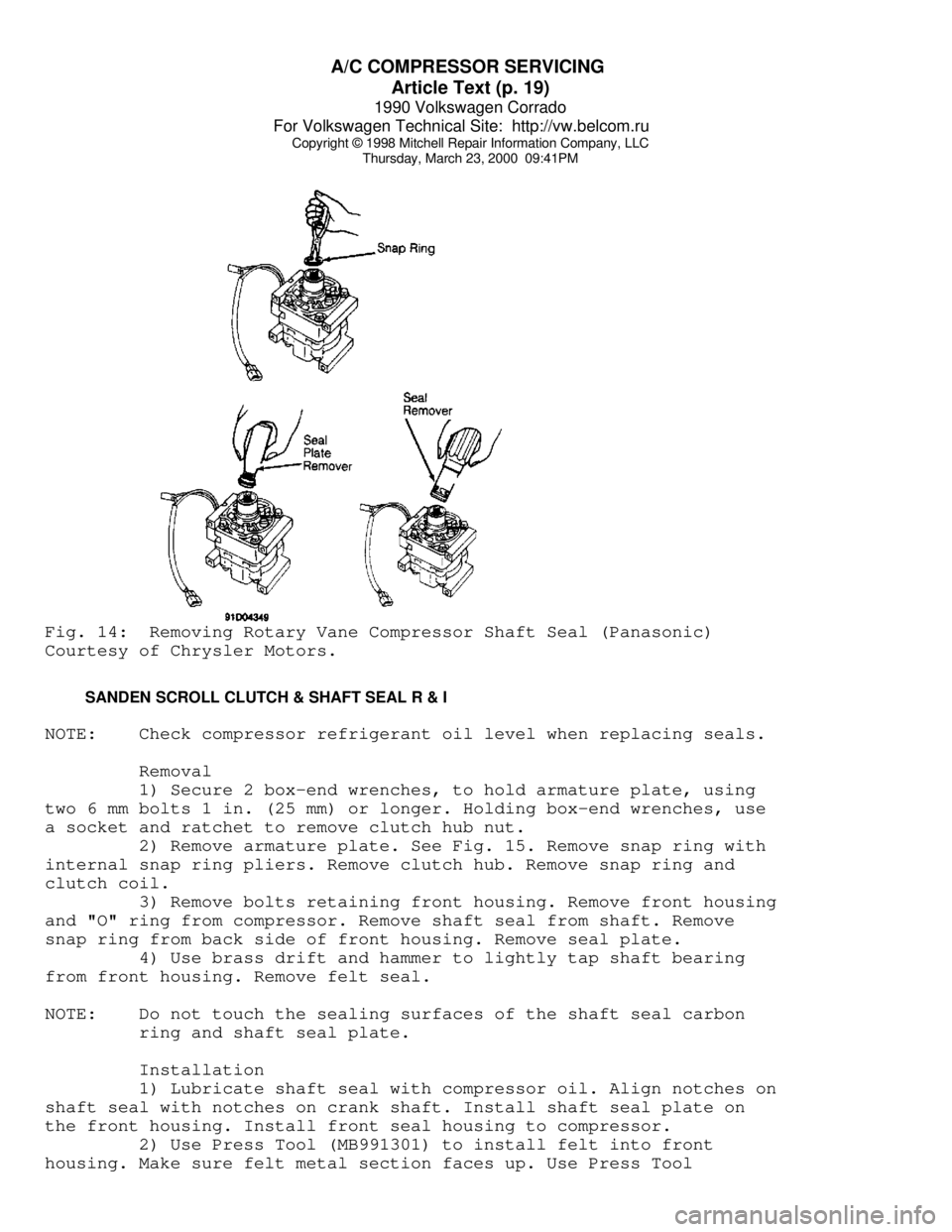
Thursday, March 23, 2000 09:41PMFig. 14: Removing Rotary Vane Compressor Shaft Seal (Panasonic)
Courtesy of Chrysler Motors.
SANDEN SCROLL CLUTCH & SHAFT SEAL R & I
NOTE: Check compressor refrigerant oil level when replacing seals.
Removal
1) Secure 2 box-end wrenches, to hold armature plate, using
two 6 mm bolts 1 in. (25 mm) or longer. Holding box-end wrenches, use
a socket and ratchet to remove clutch hub nut.
2) Remove armature plate. See Fig. 15. Remove snap ring with
internal snap ring pliers. Remove clutch hub. Remove snap ring and
clutch coil.
3) Remove bolts retaining front housing. Remove front housing
and "O" ring from compressor. Remove shaft seal from shaft. Remove
snap ring from back side of front housing. Remove seal plate.
4) Use brass drift and hammer to lightly tap shaft bearing
from front housing. Remove felt seal.
NOTE: Do not touch the sealing surfaces of the shaft seal carbon
ring and shaft seal plate.
Installation
1) Lubricate shaft seal with compressor oil. Align notches on
shaft seal with notches on crank shaft. Install shaft seal plate on
the front housing. Install front seal housing to compressor.
2) Use Press Tool (MB991301) to install felt into front
housing. Make sure felt metal section faces up. Use Press Tool
Page 353 of 906

A/C SYSTEM GENERAL DIAGNOSTIC PROCEDURES
Article Text (p. 5)
1990 Volkswagen Corrado
For Volkswagen Technical Site: http://vw.belcom.ru
Copyright © 1998 Mitchell Repair Information Company, LLC
Thursday, March 23, 2000 09:41PM
and on too rapidly. Switch
NORMAL NORMAL Cycling clutch systems only - Misadjusted
to compressor doesn't turn on Thermostatic
HIGH soon enough. Discharge air Switch or
becomes warm as low side Defective
pressure rises. Pressure
Sensing Switch
LOW LOW Bubbles in sight glass. Low R-12
Outlet air slightly cool. Charge
LOW LOW Sight glass clear. Outlet Excessively
air very warm. Low R-12
Charge
LOW LOW Outlet air slightly cool. Expansion
Sweating or frost at Valve Stuck
expansion valve. Closed Screen
Plugged or
Sensing Bulb
Malfunction
LOW LOW Outlet air slightly cool. Restriction
High side line cool to touch. on High Side
Sweating or frost on high
side.
LOW HIGH Evaporator outlet pipe cold. STV Stuck
Low side goes into vacuum Open
when blower is disconnected.
HIGH LOW Evaporator outlet pipe warm. STV Stuck
Outlet air warm. Closed
HIGH LOW Noise from compressor. Compressor
Malfunction
HIGH HIGH Outlet air warm. Liquid Compressor
line very hot. Bubbles in Malfunction
sight glass. or R-12
Overcharge
HIGH HIGH Outlet air slightly cool. Large Amount
Bubbles in sight glass. of Air and
Moisture in
System
HIGH HIGH Outlet air warm. Evaporator Expansion
outlet sweating and frost. Valve
Stuck Open
(1) - If equipped with a low refrigerant charge protection system,
compressor operation may have stopped.ÄÄÄÄÄÄÄÄÄÄÄÄÄÄÄÄÄÄÄÄÄÄÄÄÄÄÄÄÄÄÄÄÄÄÄÄÄÄÄÄÄÄÄÄÄÄÄÄÄÄÄÄÄÄÄÄÄÄÄÄÄÄÄÄÄÄÄÄÄÄEND OF ARTICLE
Page 354 of 906

A/C SYSTEM PRECAUTIONS
Article Text
1990 Volkswagen Corrado
For Volkswagen Technical Site: http://vw.belcom.ru
Copyright © 1998 Mitchell Repair Information Company, LLC
Thursday, March 23, 2000 09:41PM
ARTICLE BEGINNING
AIR CONDITIONING & HEAT
A/C System Precautions
* PLEASE READ THIS FIRST *
CAUTION: When discharging air conditioning system, use only approved
refrigerant recovery/recycling equipment. Make every attempt
to avoid discharging refrigerant into the atmosphere.
BEFORE OPENING THE SYSTEM
Before disconnecting any lines or fittings, the system must
be completely discharged using approved refrigerant recovery/recycling
equipment.
DISCHARGING A/C SYSTEM
NOTE: Recent findings by the EPA indicate that R-11, R-12 and R-113
are harmful to the Earths' protective Ozone layer. Make every
attempt possible, to avoid discharging R-11, R-12 or R-113
into the atmosphere.
1) Remove service valve caps and install gauges. For high
side gauge hose, Adapter (D81L-19703-A) must be used to connect to
high side service valve.
2) Place open end of center hose in garage exhaust outlet or
in a well ventilated area. Slightly open low side gauge valve and let
refrigerant escape slowly without loosing refrigerant oil.
3) When system is nearly discharged, using approved
refrigerant recovery/recycling equipment, open high side gauge valve
to release any pressure trapped in compressor. Close valves
immediately after discharging to prevent entry of moisture.
DISCONNECTING LINES & FITTINGS
1) After system is discharged, using approved refrigerant
recovery/recycling equipment, carefully clean entire area around
coupling nut to prevent dirt entering system. Always use two wrenches
to avoid twisting or distorting lines and fittings (hold fitting with
one wrench while loosening coupling nut with second wrench).
2) Cap or plug all LINES and FITTINGS immediately to prevent
entry of air and moisture into system. Do not remove these caps until
connections are being made.
COMPONENT REPLACEMENT
When components are replaced, system oil level must be
adjusted. Add refrigeration oil to replacement component. See