1990 VOLKSWAGEN CORRADO engine
[x] Cancel search: enginePage 548 of 906

F - BASIC TESTING
Article Text (p. 3)
1990 Volkswagen Corrado
For Volkswagen Technical Site: http://vw.belcom.ru
Copyright © 1998 Mitchell Repair Information Company, LLC
Thursday, March 23, 2000 09:44PM
CABRIOLET, GOLF GL/GTI, JETTA WITH AFC-DIGIFANT II
1) Install Fuel Pressure Gauge at service port on fuel
plenum. Fuel pressure gauge must be able to read 0-50 psi. Start
engine and allow it to idle. System fuel pressure should be
approximately 36 psi (2.5 kg/cmý).
2) Disconnect vacuum hose from top of the fuel pressure
regulator. Fuel pressure should increase to approximately 44 psi (3.0
kg/cm
ý). Turn engine off. After 10 minutes, residual pressure should
be 29 psi (2.0 kg/cm
ý). If system pressure is too high, the fuel
pressure regulator should be replaced.
3) If residual pressure is too low, run the engine until
system pressure is built up, pinch off Blue fuel return line. If
pressure holds, replace the fuel regulator.
CORRADO WITH AFC-DIGIFANT II
1) Install Fuel Pressure Gauge (VW 1318) and Adaptor (VW
3118-1 and 11) between the fuel distributor test port and pressure
switch. Bleed excess air from system cycling control valve with gauge
upside down.
2) Open fuel pressure gauge control lever, start engine and
allow to idle. Fuel pressure should be approximately 36.3 psi (2.5
kg/cm
ý). Pull hose off intake manifold fuel pressure should increase
to approximately 43.5 psi (3.0 kg/cm
ý).
3) Switch ignition off. After 10 minutes residual pressure
should be 29 psi (2.0 kg/cm
ý). If residual pressure is too low, run
the engine until system pressure is built up, pinch off Blue fuel
return line. If pressure holds, replace the fuel regulator.
If fuel pressure is low, check the following:
* Fuel lines for leaks.
* Fuel injectors leaking.
* Fuel pump check valve leaking.
* Pressure gauge stop-cock leaking.
FOX & JETTA GLI WITH CIS-E & CIS-MOTRONIC
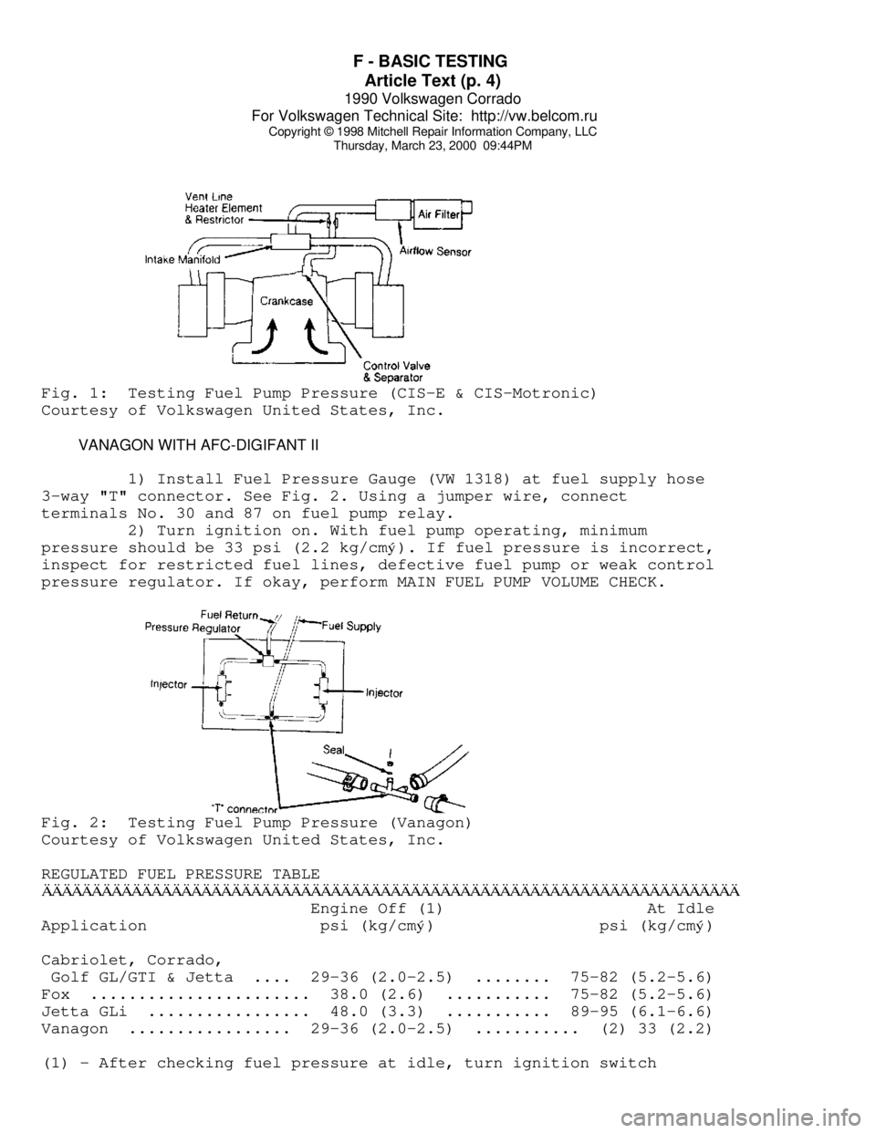
1) Connect pressure gauge (VW 1318) between fuel distributor
port and the end of the fuel line to cold start valve. Ensure control
lever is in the closed position. See Fig. 1. Bleed excess air from
system by cycling control valve with gauge upside down.
2) Open fuel pressure gauge control lever. Start engine allow
to run. System fuel pressure should 75-82 psi (5.2-5.6 kg/cm
ý). On
Jetta GLi system pressure should be 89-95 psi (6.1-6.6 kg/cm
ý). If
system fuel pressure is low, perform fuel volume check. If fuel volume
is okay, replace fuel pressure regulator.
3) If fuel pressure is above specification, remove return
hose from pressure regulator and repeat test. If system pressure is
okay, check for restricted fuel return line. If pressure is incorrect,
replace fuel pressure regulator.
Page 549 of 906
F - BASIC TESTING
Article Text (p. 4)
1990 Volkswagen Corrado
For Volkswagen Technical Site: http://vw.belcom.ru
Copyright © 1998 Mitchell Repair Information Company, LLC
Thursday, March 23, 2000 09:44PMFig. 1: Testing Fuel Pump Pressure (CIS-E & CIS-Motronic)
Courtesy of Volkswagen United States, Inc.
VANAGON WITH AFC-DIGIFANT II
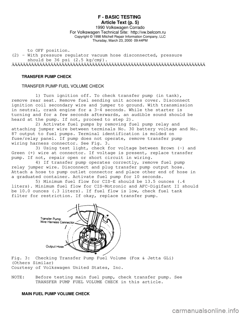
1) Install Fuel Pressure Gauge (VW 1318) at fuel supply hose
3-way "T" connector. See Fig. 2. Using a jumper wire, connect
terminals No. 30 and 87 on fuel pump relay.
2) Turn ignition on. With fuel pump operating, minimum
pressure should be 33 psi (2.2 kg/cmý). If fuel pressure is incorrect,
inspect for restricted fuel lines, defective fuel pump or weak control
pressure regulator. If okay, perform MAIN FUEL PUMP VOLUME CHECK.Fig. 2: Testing Fuel Pump Pressure (Vanagon)
Courtesy of Volkswagen United States, Inc.
REGULATED FUEL PRESSURE TABLE
ÄÄÄÄÄÄÄÄÄÄÄÄÄÄÄÄÄÄÄÄÄÄÄÄÄÄÄÄÄÄÄÄÄÄÄÄÄÄÄÄÄÄÄÄÄÄÄÄÄÄÄÄÄÄÄÄÄÄÄÄÄÄÄÄÄÄÄÄÄÄ Engine Off (1) At Idle
Application psi (kg/cm
ý) psi (kg/cmý)
Cabriolet, Corrado,
Golf GL/GTI & Jetta .... 29-36 (2.0-2.5) ........ 75-82 (5.2-5.6)
Fox ....................... 38.0 (2.6) ........... 75-82 (5.2-5.6)
Jetta GLi ................. 48.0 (3.3) ........... 89-95 (6.1-6.6)
Vanagon ................. 29-36 (2.0-2.5) ........... (2) 33 (2.2)
(1) - After checking fuel pressure at idle, turn ignition switch
Page 550 of 906
F - BASIC TESTING
Article Text (p. 5)
1990 Volkswagen Corrado
For Volkswagen Technical Site: http://vw.belcom.ru
Copyright © 1998 Mitchell Repair Information Company, LLC
Thursday, March 23, 2000 09:44PM
to OFF position.
(2) - With pressure regulator vacuum hose disconnected, pressure
should be 36 psi (2.5 kg/cmý).
ÄÄÄÄÄÄÄÄÄÄÄÄÄÄÄÄÄÄÄÄÄÄÄÄÄÄÄÄÄÄÄÄÄÄÄÄÄÄÄÄÄÄÄÄÄÄÄÄÄÄÄÄÄÄÄÄÄÄÄÄÄÄÄÄÄÄÄÄÄÄ TRANSFER PUMP CHECK
TRANSFER PUMP FUEL VOLUME CHECK
1) Turn ignition off. To check transfer pump (in tank),
remove rear seat. Remove fuel sending unit access cover. Disconnect
ignition coil secondary wire and jumper to ground. With transmission
in neutral, crank engine for a 3-4 seconds. While the starter is
turning and for a few seconds afterwards, an audible sound should be
heard at the pump. If not, proceed to step 2).
2) Activate fuel pumps by removing fuel pump relay and
attaching jumper wire between terminals No. 30 battery voltage and No.
87 output to fuel pumps. Terminal identification is molded on
fuse/relay panel. If pump does not operate, remove transfer pump
wiring harness connector. See Fig. 3.
3) Using test light, check for voltage between Brown (-) and
Green (+) wire at connector. If voltage is present, replace transfer
pump. If not, repair open or short circuit in wiring.
4) If transfer pump operates correctly, remove fuel pump
relay jumper wire. Disconnect and plug transfer pump output hose.
Attach a hose to pump outlet connector and place other end of hose in
a graduated container. Activate fuel pump for 10 seconds.
5) Minimum fuel flow for CIS-E should be 13.5 ounces (.4
liters). Minimum fuel flow for CIS-Motronic and AFC-Digifant II should
be 10.0 ounces (.3 liters). If fuel flow is low, check fuel tank
filter for restriction. If okay, replace transfer pump.Fig. 3: Checking Transfer Pump Fuel Volume (Fox & Jetta GLi)
(Others Similar)
Courtesy of Volkswagen United States, Inc.
NOTE: Before testing main fuel pump, check transfer pump. See
TRANSFER PUMP FUEL VOLUME CHECK in this article.
MAIN FUEL PUMP VOLUME CHECK
Page 551 of 906

F - BASIC TESTING
Article Text (p. 6)
1990 Volkswagen Corrado
For Volkswagen Technical Site: http://vw.belcom.ru
Copyright © 1998 Mitchell Repair Information Company, LLC
Thursday, March 23, 2000 09:44PM
ALL EXCEPT CORRADO & VANAGON
1) Remove fuel return line located near left strut tower.
Remove fuel tank cap. Attach a piece of hose between return line and a
1 qt. (.95 liter) graduated container.
2) Activate fuel pump for 30 seconds by removing fuel pump
relay and attaching jumper wire between terminals No. 30 and No. 87.
Remove fuel pump relay from fuse/relay block. Compare volume with
specifications.
CORRADO
1) Disconnect wire harness connector from fuel pump. See
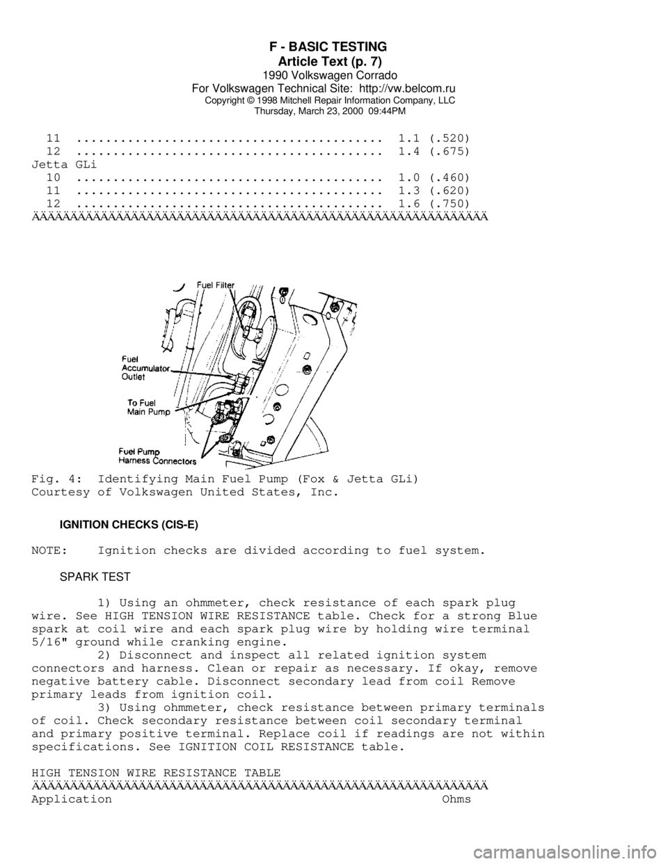
Fig. 4. With voltmeter attached to terminals, activate fuel pump by
removing fuel pump relay and applying battery voltage to terminals No.
4 of the fuse box connection for the fuel pump relay. Fuel pump relay
located on fuse box housing. Terminal numbers are molded into fuse box
plastic housing.
2) Record voltage. Remove fuel line from outlet side of
accumulator. See Fig. 4. Attach a piece of hose between return line
and a graduated container. Activate fuel pump for 30 seconds. Compare
volume with specifications given in MAIN FUEL PUMP VOLUME (AFC-
Digifant II) table.
VANAGON
1) Remove the return line from the pressure regulator located
in engine compartment left side. Push a piece of hose onto open
connection of pressure regulator. Insert hose into a 1 qt. (1 liter)
graduated container.
2) Activate fuel pump for 30 seconds by removing fuel pump
relay and attaching jumper wire between terminals No. 30 and No. 87.
Fuel pump relay located left side of engine compartment in Black
plastic box. Compare volume with specifications.
FUEL PUMP PERFORMANCE TABLE (AFC-DIGIFANT II)ÄÄÄÄÄÄÄÄÄÄÄÄÄÄÄÄÄÄÄÄÄÄÄÄÄÄÄÄÄÄÄÄÄÄÄÄÄÄÄÄÄÄÄÄÄÄÄÄÄÄÄÄÄÄÄÄÄÄÄÄÄÄÄÄÄÄÄÄÄÄ Pressure Min. Vol. in 30 Sec.
Application psi (kg/cm
ý) Pts. (L)
Cabriolet, Corrado,
Golf GL/GTI & Jetta .... 29-36 (2.0-2.5) ............... 1.0 (.5)
Vanagon ................. 33-39 (2.3-2.7) ............... 1.0 (.5)
ÄÄÄÄÄÄÄÄÄÄÄÄÄÄÄÄÄÄÄÄÄÄÄÄÄÄÄÄÄÄÄÄÄÄÄÄÄÄÄÄÄÄÄÄÄÄÄÄÄÄÄÄÄÄÄÄÄÄÄÄÄÄÄÄÄÄÄÄÄÄFUEL PUMP PERFORMANCE TABLE (CIS-E & CIS-MOTRONIC)
ÄÄÄÄÄÄÄÄÄÄÄÄÄÄÄÄÄÄÄÄÄÄÄÄÄÄÄÄÄÄÄÄÄÄÄÄÄÄÄÄÄÄÄÄÄÄÄÄÄÄÄÄÄÄÄÄÄÄÄÄApplication @ Voltage Min. Vol. in 30 Sec. Pts. (L)
Fox
10 ........................................... .8 (.375)
Page 552 of 906
F - BASIC TESTING
Article Text (p. 7)
1990 Volkswagen Corrado
For Volkswagen Technical Site: http://vw.belcom.ru
Copyright © 1998 Mitchell Repair Information Company, LLC
Thursday, March 23, 2000 09:44PM
11 .......................................... 1.1 (.520)
12 .......................................... 1.4 (.675)
Jetta GLi
10 .......................................... 1.0 (.460)
11 .......................................... 1.3 (.620)
12 .......................................... 1.6 (.750)ÄÄÄÄÄÄÄÄÄÄÄÄÄÄÄÄÄÄÄÄÄÄÄÄÄÄÄÄÄÄÄÄÄÄÄÄÄÄÄÄÄÄÄÄÄÄÄÄÄÄÄÄÄÄÄÄÄÄÄÄFig. 4: Identifying Main Fuel Pump (Fox & Jetta GLi)
Courtesy of Volkswagen United States, Inc.
IGNITION CHECKS (CIS-E)
NOTE: Ignition checks are divided according to fuel system.
SPARK TEST
1) Using an ohmmeter, check resistance of each spark plug
wire. See HIGH TENSION WIRE RESISTANCE table. Check for a strong Blue
spark at coil wire and each spark plug wire by holding wire terminal
5/16" ground while cranking engine.
2) Disconnect and inspect all related ignition system
connectors and harness. Clean or repair as necessary. If okay, remove
negative battery cable. Disconnect secondary lead from coil Remove
primary leads from ignition coil.
3) Using ohmmeter, check resistance between primary terminals
of coil. Check secondary resistance between coil secondary terminal
and primary positive terminal. Replace coil if readings are not within
specifications. See IGNITION COIL RESISTANCE table.
HIGH TENSION WIRE RESISTANCE TABLE
ÄÄÄÄÄÄÄÄÄÄÄÄÄÄÄÄÄÄÄÄÄÄÄÄÄÄÄÄÄÄÄÄÄÄÄÄÄÄÄÄÄÄÄÄÄÄÄÄÄÄÄÄÄÄÄÄÄÄÄÄApplication Ohms
Page 553 of 906
F - BASIC TESTING
Article Text (p. 8)
1990 Volkswagen Corrado
For Volkswagen Technical Site: http://vw.belcom.ru
Copyright © 1998 Mitchell Repair Information Company, LLC
Thursday, March 23, 2000 09:44PM
Fox
Coil Wire With Connectors .................... 1600-2400
Spark Plug Wire With Connectors .............. 4800-7200
Spark Plug Connector ......................... 4000-6000
Suppressor .................................... 800-1200ÄÄÄÄÄÄÄÄÄÄÄÄÄÄÄÄÄÄÄÄÄÄÄÄÄÄÄÄÄÄÄÄÄÄÄÄÄÄÄÄÄÄÄÄÄÄÄÄÄÄÄÄÄÄÄÄÄÄÄÄ IGNITION COIL RESISTANCE TABLE
IGNITION COIL RESISTANCE TABLE - Ohms @ 68
øF (20øC)
ÄÄÄÄÄÄÄÄÄÄÄÄÄÄÄÄÄÄÄÄÄÄÄÄÄÄÄÄÄÄÄÄÄÄÄÄÄÄÄÄÄÄÄÄÄÄÄÄÄÄÄÄÄÄÄÄÄÄÄÄApplication Primary Secondary
Jetta GLi 2.0L ......... .60-.70 ............. 6500-8500
All Other Models ....... .52-.76 ............. 2400-3500
ÄÄÄÄÄÄÄÄÄÄÄÄÄÄÄÄÄÄÄÄÄÄÄÄÄÄÄÄÄÄÄÄÄÄÄÄÄÄÄÄÄÄÄÄÄÄÄÄÄÄÄÄÄÄÄÄÄÄÄÄ DISTRIBUTOR
HALL EFFECT SENDER
1) Remove coil secondary and attach to ground. Disconnect
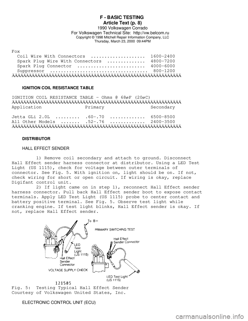
Hall Effect sender harness connector at distributor. Using a LED Test
Light (US 1115), check for voltage between outer terminals of
connector. See Fig. 5. With ignition on, light should be on. If not,
check wiring for short or open circuit. If wiring is okay, replace
Digifant control unit.
2) If light came on in step 1), reconnect Hall Effect sender
harness connector. Pull back Hall Effect sender boot to expose contact
terminals. Apply LED Test Light (US 1115) probe to center contact and
battery positive terminal. See Fig. 5. Observe test light while
cranking engine. If test light blinks, Hall Effect sender is okay. If
not, replace Hall Effect sender.Fig. 5: Testing Typical Hall Effect Sender
Courtesy of Volkswagen United States, Inc.
ELECTRONIC CONTROL UNIT (ECU)
Page 554 of 906
F - BASIC TESTING
Article Text (p. 9)
1990 Volkswagen Corrado
For Volkswagen Technical Site: http://vw.belcom.ru
Copyright © 1998 Mitchell Repair Information Company, LLC
Thursday, March 23, 2000 09:44PM
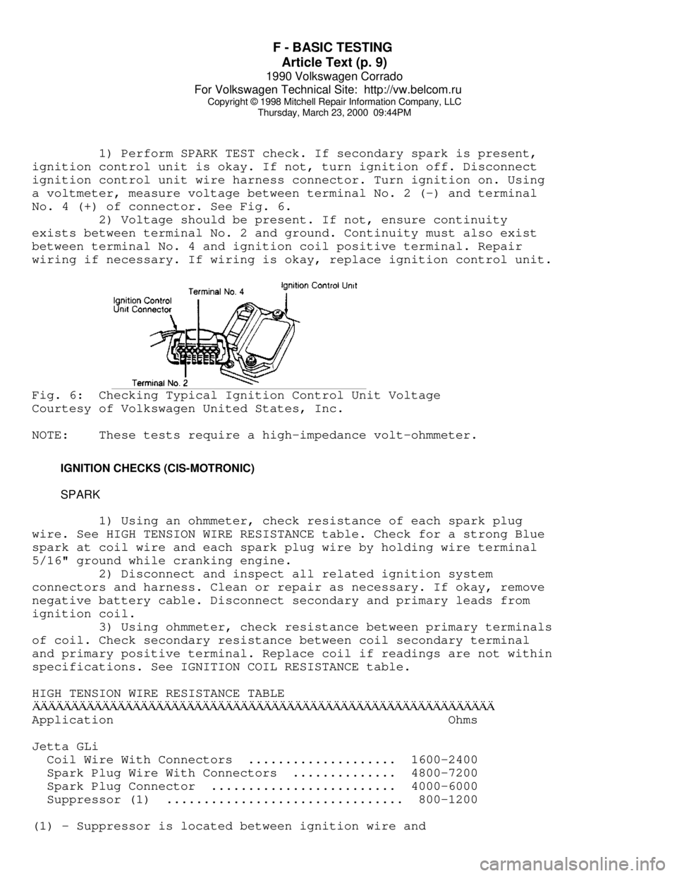
1) Perform SPARK TEST check. If secondary spark is present,
ignition control unit is okay. If not, turn ignition off. Disconnect
ignition control unit wire harness connector. Turn ignition on. Using
a voltmeter, measure voltage between terminal No. 2 (-) and terminal
No. 4 (+) of connector. See Fig. 6.
2) Voltage should be present. If not, ensure continuity
exists between terminal No. 2 and ground. Continuity must also exist
between terminal No. 4 and ignition coil positive terminal. Repair
wiring if necessary. If wiring is okay, replace ignition control unit.Fig. 6: Checking Typical Ignition Control Unit Voltage
Courtesy of Volkswagen United States, Inc.
NOTE: These tests require a high-impedance volt-ohmmeter.
IGNITION CHECKS (CIS-MOTRONIC)
SPARK
1) Using an ohmmeter, check resistance of each spark plug
wire. See HIGH TENSION WIRE RESISTANCE table. Check for a strong Blue
spark at coil wire and each spark plug wire by holding wire terminal
5/16" ground while cranking engine.
2) Disconnect and inspect all related ignition system
connectors and harness. Clean or repair as necessary. If okay, remove
negative battery cable. Disconnect secondary and primary leads from
ignition coil.
3) Using ohmmeter, check resistance between primary terminals
of coil. Check secondary resistance between coil secondary terminal
and primary positive terminal. Replace coil if readings are not within
specifications. See IGNITION COIL RESISTANCE table.
HIGH TENSION WIRE RESISTANCE TABLEÄÄÄÄÄÄÄÄÄÄÄÄÄÄÄÄÄÄÄÄÄÄÄÄÄÄÄÄÄÄÄÄÄÄÄÄÄÄÄÄÄÄÄÄÄÄÄÄÄÄÄÄÄÄÄÄÄÄÄÄApplication Ohms
Jetta GLi
Coil Wire With Connectors .................... 1600-2400
Spark Plug Wire With Connectors .............. 4800-7200
Spark Plug Connector ......................... 4000-6000
Suppressor (1) ................................ 800-1200
(1) - Suppressor is located between ignition wire and
Page 556 of 906
F - BASIC TESTING
Article Text (p. 11)
1990 Volkswagen Corrado
For Volkswagen Technical Site: http://vw.belcom.ru
Copyright © 1998 Mitchell Repair Information Company, LLC
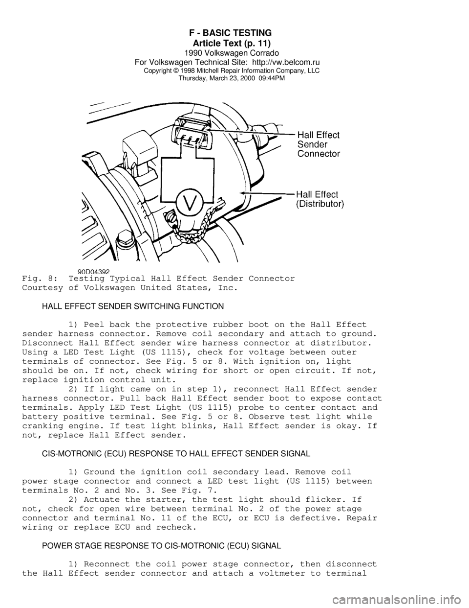
Thursday, March 23, 2000 09:44PMFig. 8: Testing Typical Hall Effect Sender Connector
Courtesy of Volkswagen United States, Inc.
HALL EFFECT SENDER SWITCHING FUNCTION
1) Peel back the protective rubber boot on the Hall Effect
sender harness connector. Remove coil secondary and attach to ground.
Disconnect Hall Effect sender wire harness connector at distributor.
Using a LED Test Light (US 1115), check for voltage between outer
terminals of connector. See Fig. 5 or 8. With ignition on, light
should be on. If not, check wiring for short or open circuit. If not,
replace ignition control unit.
2) If light came on in step 1), reconnect Hall Effect sender
harness connector. Pull back Hall Effect sender boot to expose contact
terminals. Apply LED Test Light (US 1115) probe to center contact and
battery positive terminal. See Fig. 5 or 8. Observe test light while
cranking engine. If test light blinks, Hall Effect sender is okay. If
not, replace Hall Effect sender.
CIS-MOTRONIC (ECU) RESPONSE TO HALL EFFECT SENDER SIGNAL
1) Ground the ignition coil secondary lead. Remove coil
power stage connector and connect a LED test light (US 1115) between
terminals No. 2 and No. 3. See Fig. 7.
2) Actuate the starter, the test light should flicker. If
not, check for open wire between terminal No. 2 of the power stage
connector and terminal No. 11 of the ECU, or ECU is defective. Repair
wiring or replace ECU and recheck.
POWER STAGE RESPONSE TO CIS-MOTRONIC (ECU) SIGNAL
1) Reconnect the coil power stage connector, then disconnect
the Hall Effect sender connector and attach a voltmeter to terminal