1990 VOLKSWAGEN CORRADO warning light
[x] Cancel search: warning lightPage 412 of 906

ANTI-LOCK BRAKE SYSTEM
Article Text (p. 4)
1990 Volkswagen Corrado
For Volkswagen Technical Site: http://vw.belcom.ru
Copyright © 1998 Mitchell Repair Information Company, LLC
Thursday, March 23, 2000 09:42PM
seconds maximum and then stop. Depress brake pedal a few times; pump
should operate again for a few seconds. If pump motor does not
operate, check electrical system. If pump motor operates for more than
60 seconds, internal or external hydraulic leak may be indicated.
Check for external leaks. If external leak is not found, further
testing may be needed to check for internal leaks.
ANTI-LOCK WARNING LIGHT
Start engine. ANTI-LOCK warning light should come on, then
turn off after a few seconds. If light does not come on when engine is
started, check electrical system. If light comes on and stays on,
fault has been detected by the ECU and testing will be needed. See
SYSTEM TESTING under DIAGNOSIS & TESTING.
DIAGNOSIS & TESTING
SYSTEM TESTING
NOTE: Check battery condition, brake fluid level, electrical
connections and wiring for damage. If fluid level is
incorrect or battery and/or electrical connections are
faulty, correct problem before preceding. Perform each step,
in sequence, to test entire system, except for ECU. If
faulty ECU is suspected, replace with a known good one, and
retest system. Unplug ECU connector for all test steps.
Power Voltage-To-ECU Test
Turn ignition off. Unplug ECU connector. Turn ignition on.
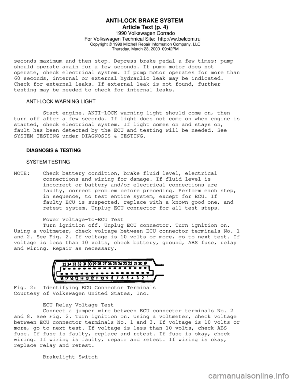
Using a voltmeter, check voltage between ECU connector terminals No. 1
and 2. See Fig. 2. If voltage is 10 volts or more, go to next test. If
voltage is less than 10 volts, check battery, ground, ABS fuse, relay
and wiring. Repair as necessary.Fig. 2: Identifying ECU Connector Terminals
Courtesy of Volkswagen United States, Inc.
ECU Relay Voltage Test
Connect a jumper wire between ECU connector terminals No. 2
and 8. See Fig. 2. Turn ignition on. Using a voltmeter, check voltage
between ECU connector terminals No. 1 and 3. If voltage is 10 volts or
more, go to next test. If voltage is less than 10 volts, check ABS
fuse. If fuse is faulty, replace and retest. If fuse is okay, check
wiring. If wiring is faulty, repair and retest. If wiring is okay,
replace relay and retest.
Brakelight Switch
Page 418 of 906

ANTI-LOCK BRAKE SYSTEM
Article Text (p. 10)
1990 Volkswagen Corrado
For Volkswagen Technical Site: http://vw.belcom.ru
Copyright © 1998 Mitchell Repair Information Company, LLC
Thursday, March 23, 2000 09:42PM
modulator terminals No. 1 (Brown wire) and 6 (Black/Blue wire). See
Fig. 4-9. If resistance is 3-5 ohms, check wiring between hydraulic
modulator and ECU for open circuit. If resistance is not 3-5 ohms,
replace hydraulic modulator.
Hydraulic Modulator/Pump Relay Resistance Test
Turn ignition off. Unplug pressure switch connector from
hydraulic modulator. Using an ohmmeter, measure resistance between ECU
connector terminals No. 2 and 14. See Fig. 2. If resistance is 50-100
ohms, go to next test. If resistance is not 50-100 ohms, check wiring.
If wiring is faulty, repair wiring and retest. If wiring is okay,
replace relay and retest.
ABS Main Valve Function Test
Connect a jumper wire between ECU connector terminals No. 2
and 18. See Fig. 2. Depress brake pedal. Turn ignition on. Brake pedal
should rise slightly. If brake pedal did not rise slightly, check
wiring between terminals and hydraulic modulator. If wiring is okay,
replace hydraulic modulator.
Hydraulic Modulator/Pump Test
Turn ignition off. Depress brake pedal 25 times. Turn
ignition on. BRAKE and ANTI-LOCK lights should come on for 2-60
seconds. Pump should operate for 2-60 seconds, then turn off. If
lights do not come on, check wiring and warning light bulbs, and
retest. Also check bulb(s). If lights come on, then turn off, and pump
operates for 60 seconds maximum, then turns off, go to next test. If
pump does not operate and all other preceding tests have been
performed, replace hydraulic modulator/pump.
CAUTION: During VALVE BLOCK FUNCTION TESTS, DO NOT turn ignition on
longer than 60 seconds during any test.
Rear Valve Block Function Test
Connect a jumper wire ECU between ECU connector terminals No.
2, 17 and 33. See Fig. 2. Depress brake pedal. Rear wheels should be
locked up. Turn ignition on. Rear wheels should rotate. If wheels do
not rotate, replace hydraulic modulator. Turn ignition off.
Right Front Valve Block Function Test
Connect a jumper wire ECU between ECU connector terminals No.
2, 15 and 34. See Fig. 2. Depress brake pedal. Right front wheel
should be locked up. Turn ignition on. Right front wheel should
rotate. If wheel do not rotate, replace hydraulic modulator. Turn
ignition off.
Left Front Valve Block Function Test
Connect a jumper wire ECU between ECU connector terminals No.
2, 16 and 35. See Fig. 2. Depress brake pedal. Left front wheel should
be locked up. Turn ignition on. Left front wheel should rotate. If
wheel do not rotate, replace hydraulic modulator. Turn ignition off.
Page 458 of 906

E - THEORY/OPERATION - DIGIFANT
Article Text (p. 8)
1990 Volkswagen Corrado
For Volkswagen Technical Site: http://vw.belcom.ru
Copyright © 1998 Mitchell Repair Information Company, LLC
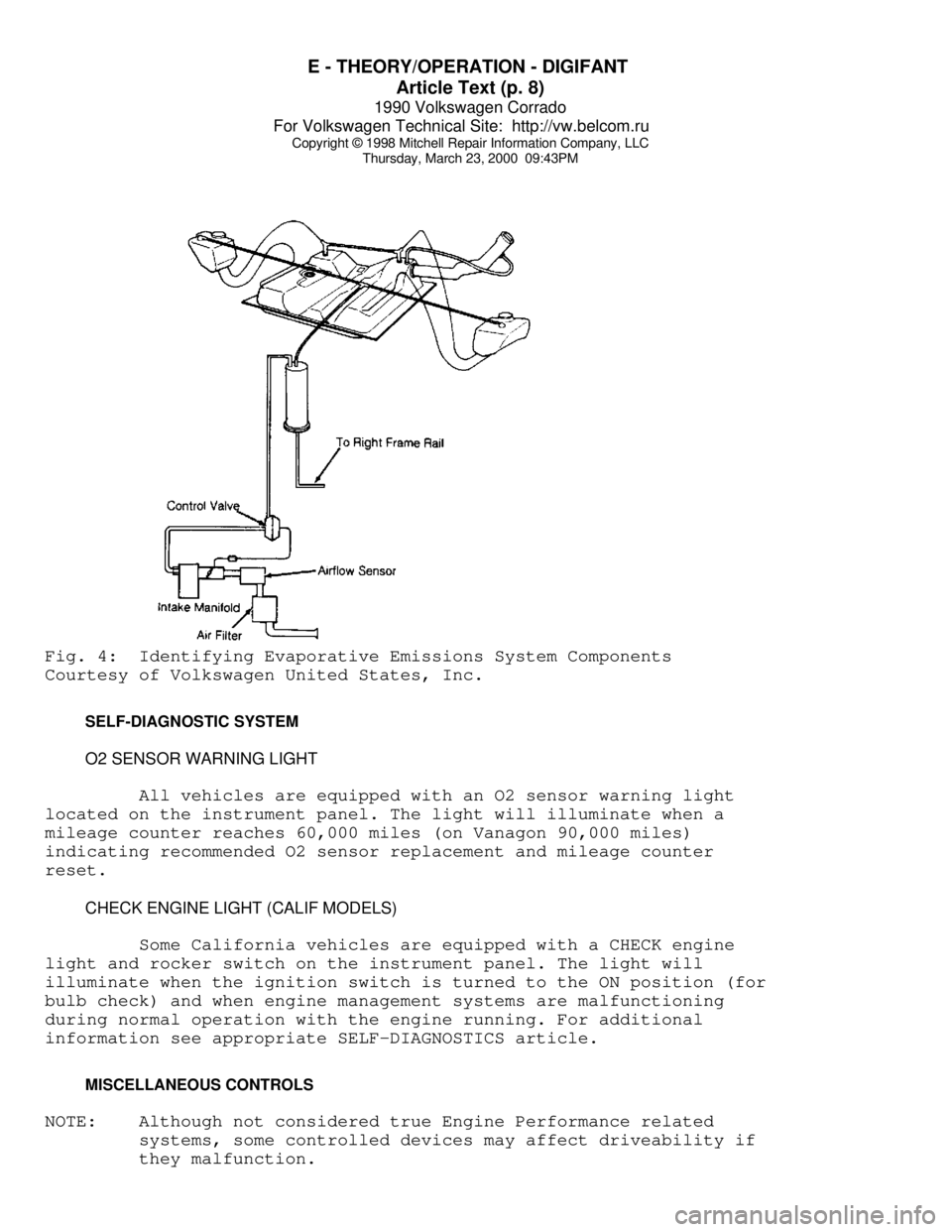
Thursday, March 23, 2000 09:43PMFig. 4: Identifying Evaporative Emissions System Components
Courtesy of Volkswagen United States, Inc.
SELF-DIAGNOSTIC SYSTEM
O2 SENSOR WARNING LIGHT
All vehicles are equipped with an O2 sensor warning light
located on the instrument panel. The light will illuminate when a
mileage counter reaches 60,000 miles (on Vanagon 90,000 miles)
indicating recommended O2 sensor replacement and mileage counter
reset.
CHECK ENGINE LIGHT (CALIF MODELS)
Some California vehicles are equipped with a CHECK engine
light and rocker switch on the instrument panel. The light will
illuminate when the ignition switch is turned to the ON position (for
bulb check) and when engine management systems are malfunctioning
during normal operation with the engine running. For additional
information see appropriate SELF-DIAGNOSTICS article.
MISCELLANEOUS CONTROLS
NOTE: Although not considered true Engine Performance related
systems, some controlled devices may affect driveability if
they malfunction.
Page 488 of 906

ELECTRICAL COMPONENT LOCATOR
Article Text (p. 29)
1990 Volkswagen Corrado
For Volkswagen Technical Site: http://vw.belcom.ru
Copyright © 1998 Mitchell Repair Information Company, LLC
Thursday, March 23, 2000 09:44PM
Wheel Speed Sensor Mounted near hub assembly.ÄÄÄÄÄÄÄÄÄÄÄÄÄÄÄÄÄÄÄÄÄÄÄÄÄÄÄÄÄÄÄÄÄÄÄÄÄÄÄÄÄÄÄÄÄÄÄÄÄÄÄÄÄÄÄÄÄÄÄÄÄÄÄÄÄÄÄÄÄÄ SOLENOIDS & SOLENOID VALVES
ÄÄÄÄÄÄÄÄÄÄÄÄÄÄÄÄÄÄÄÄÄÄÄÄÄÄÄÄÄÄÄÄÄÄÄÄÄÄÄÄÄÄÄÄÄÄÄÄÄÄÄÄÄÄÄÄÄÄÄÄÄÄÄÄÄÄÄÄÄÄComponent Component Location
ÄÄÄÄÄÄÄÄÄÄÄÄÄÄÄÄÄÄÄÄÄÄÄÄÄÄÄÄÄÄÄÄÄÄÄÄÄÄÄÄÄÄÄÄÄÄÄÄÄÄÄÄÄÄÄÄÄÄÄÄÄÄÄÄÄÄÄÄÄÄIdle Stabilizer Valve Across from throttle valve,
near valve cover.
ÄÄÄÄÄÄÄÄÄÄÄÄÄÄÄÄÄÄÄÄÄÄÄÄÄÄÄÄÄÄÄÄÄÄÄÄÄÄÄÄÄÄÄÄÄÄÄÄÄÄÄÄÄÄÄÄÄÄÄÄÄÄÄÄÄÄÄÄÄÄ SWITCHES
ÄÄÄÄÄÄÄÄÄÄÄÄÄÄÄÄÄÄÄÄÄÄÄÄÄÄÄÄÄÄÄÄÄÄÄÄÄÄÄÄÄÄÄÄÄÄÄÄÄÄÄÄÄÄÄÄÄÄÄÄÄÄÄÄÄÄÄÄÄÄComponent Component Location
ÄÄÄÄÄÄÄÄÄÄÄÄÄÄÄÄÄÄÄÄÄÄÄÄÄÄÄÄÄÄÄÄÄÄÄÄÄÄÄÄÄÄÄÄÄÄÄÄÄÄÄÄÄÄÄÄÄÄÄÄÄÄÄÄÄÄÄÄÄÄA/C Pressure Switch In refrigerant line, near left
side of condenser.
Anti-Lock Brake (ABS) Pressure
Warning Switch Mounted in hydraulic modulator
below brake fluid reservoir.
Back-Up Light Switch Mounted near gear selector on
transmission.
Brake Fluid Level Switch In cap on brake fluid
reservoir.
Page 547 of 906

F - BASIC TESTING
Article Text (p. 2)
1990 Volkswagen Corrado
For Volkswagen Technical Site: http://vw.belcom.ru
Copyright © 1998 Mitchell Repair Information Company, LLC
Thursday, March 23, 2000 09:44PM
exhaust system backpressure is greater than 1 3/4-2 psi, exhaust
system or catalytic converter is plugged.
If a vacuum gauge is used, connect vacuum gauge hose to
intake manifold vacuum port and start engine. Observe vacuum gauge.
Open throttle part way and hold steady. If vacuum gauge reading slowly
drops after stabilizing, exhaust system should be checked for a
restriction.
FUEL SYSTEM APPLICATION TABLE
FUEL SYSTEM APPLICATION TABLEÄÄÄÄÄÄÄÄÄÄÄÄÄÄÄÄÄÄÄÄÄÄÄÄÄÄÄÄÄÄÄÄÄÄÄÄÄÄÄÄÄÄÄÄÄÄÄÄÄÄÄÄÄÄÄÄÄÄÄÄApplication Fuel System
Cabriolet, Corrado, Golf GL/GTI
Jetta & Vanagon ........................ AFC-Digifant II
Fox ................................................ CIS-E
Jetta GLi ................................... CIS-Motronic
ÄÄÄÄÄÄÄÄÄÄÄÄÄÄÄÄÄÄÄÄÄÄÄÄÄÄÄÄÄÄÄÄÄÄÄÄÄÄÄÄÄÄÄÄÄÄÄÄÄÄÄÄÄÄÄÄÄÄÄÄ FUEL PRESSURE CHECK
Basic diagnosis of fuel system should begin with determining
fuel system pressure.
FUEL PUMP CIRCUIT CHECK
Remove fuel tank cap. Turn ignition on and listen for fuel
pump operating sound for approximately 2 seconds. If there is no
sound, check fuse, fuel pump relay, fuel pump and all electrical
connections.
VISUAL CHECK (AFC-DIGIFANT II)
Push air door open, slight resistance should be felt and door
should not bind. Uniform resistance should be felt throughout travel
after slight amount of free travel. No binding should be felt when air
door is released.
VISUAL CHECK (CIS-E & CIS-MOTRONIC)
Move sensor plate slowly upward. Sensor plate should have
slight resistance from control piston adjusting lever. No binding
should be felt. Let sensor plate fall. There should no resistance.
Slight fuel seepage past control piston is acceptable.
FUEL PRESSURE TEST
WARNING: ALWAYS relieve fuel pressure before disconnecting any fuel
injection-related component. DO NOT allow fuel to contact
engine or electrical components.
Page 563 of 906

FUSES & CIRCUIT BREAKERS
Article Text
1990 Volkswagen Corrado
For Volkswagen Technical Site: http://vw.belcom.ru
Copyright © 1998 Mitchell Repair Information Company, LLC
Thursday, March 23, 2000 09:45PM
ARTICLE BEGINNING
1990-94 ELECTRICAL
Volkswagen Fuses & Circuit Breakers
Corrado
FUSES & CIRCUIT BREAKERS
FUSE PANEL LOCATION
Fuse panel is located under left side of dash board by
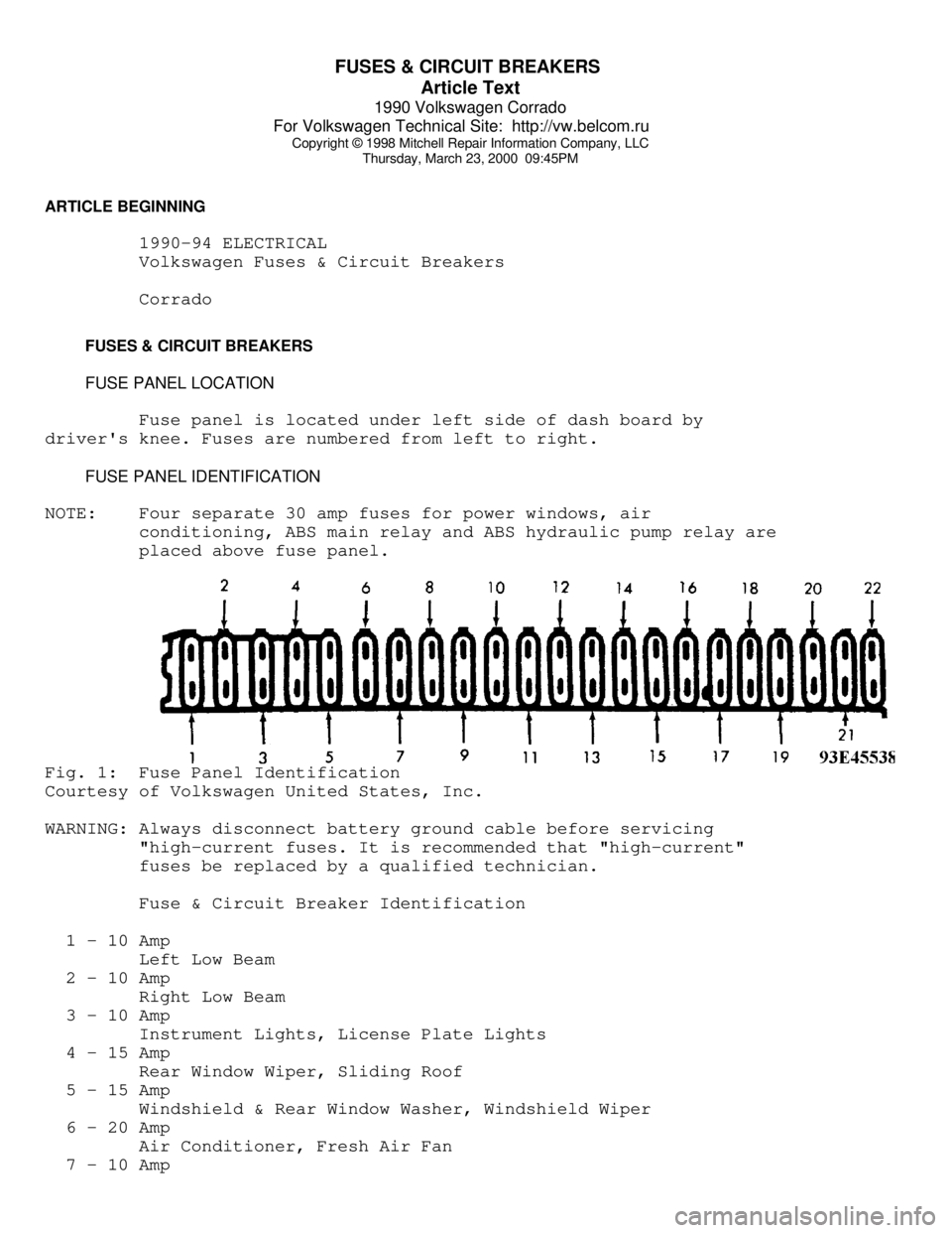
driver's knee. Fuses are numbered from left to right.
FUSE PANEL IDENTIFICATION
NOTE: Four separate 30 amp fuses for power windows, air
conditioning, ABS main relay and ABS hydraulic pump relay are
placed above fuse panel.Fig. 1: Fuse Panel Identification
Courtesy of Volkswagen United States, Inc.
WARNING: Always disconnect battery ground cable before servicing
"high-current fuses. It is recommended that "high-current"
fuses be replaced by a qualified technician.
Fuse & Circuit Breaker Identification
1 - 10 Amp
Left Low Beam
2 - 10 Amp
Right Low Beam
3 - 10 Amp
Instrument Lights, License Plate Lights
4 - 15 Amp
Rear Window Wiper, Sliding Roof
5 - 15 Amp
Windshield & Rear Window Washer, Windshield Wiper
6 - 20 Amp
Air Conditioner, Fresh Air Fan
7 - 10 Amp
Page 564 of 906

FUSES & CIRCUIT BREAKERS
Article Text (p. 2)
1990 Volkswagen Corrado
For Volkswagen Technical Site: http://vw.belcom.ru
Copyright © 1998 Mitchell Repair Information Company, LLC
Thursday, March 23, 2000 09:45PM
Right Tail & Side Lights
8 - 10 Amp
Left Tail & Side Lights
9 - 20 Amp
Rear Window & Mirror Heating
10 - 15 Amp
Foglights
11 - 10 Amp
Left High Beam, High Beam Indicator
12 - 10 Amp
Right High Beam
13 - 10 Amp
Horn, Radiator Fan
14 - 15 Amp
Back-Up Lights, Electric Mirrors, Heated Windshield Washer
Jets
15 - 10 Amp
Engine Electronic
16 - 15 Amp
Warning/Indicator Lights, Multi-Function Indicator, Glove Box
Light, Cassette Storage Light, Rear Spoiler
17 - 10 Amp
Turn Signals
18 - 20 Amp
Fuel Pump, Oxygen Sensor
19 - 30 Amp
Radiator Fan, Air Conditioner
20 - 10 Amp
Brakelights, Cruise Control
21 - 15 Amp
Dome & Luggage Compartment Lights, Cigarette Lighter, Central
Locking System, Multi-Function Indicator
22 - 10 Amp
Radio
CAUTIONS & WARNINGS
ELECTRICAL SHOCK
WARNING: Contact with live components of ignition system while
engine is running could lead to a fatal electric shock.
RADIATOR FAN
Keep hands away from radiator fan. Fan is controlled by a
thermostatic switch which may come on or run for up to 15 minutes even
after engine is turned off.
RADIATOR CAP
CAUTION: Always disconnect the fan motor when working near the
radiator fan. The fan is temperature controlled and could
Page 565 of 906

FUSES & CIRCUIT BREAKERS
Article Text (p. 3)
1990 Volkswagen Corrado
For Volkswagen Technical Site: http://vw.belcom.ru
Copyright © 1998 Mitchell Repair Information Company, LLC
Thursday, March 23, 2000 09:45PM
start at any time even when the ignition key is in the OFF
position. DO NOT loosen or remove radiator cap when cooling
system is hot.
REPLACING BLOWN FUSES
Before replacing a blown fuse, remove ignition key, turn off
all lights and accessories to avoid damaging the electrical system. Be
sure to use fuse with the correct indicated amperage rating. The use
of an incorrect amperage rating fuse may result in a dangerous
electrical system overload.
BATTERY WARNING
WARNING: When battery is disconnected, vehicles equipped with
computers may lose memory data. When battery power is
restored, driveability problems may exist on some vehicles.
These vehicles may require a relearn procedure. See COMPUTER
RELEARN PROCEDURES article in GENERAL INFORMATION section.
BRAKE PAD WEAR INDICATOR
Indicator will cause a squealing or scraping noise, warning
that brake pads need replacement.
HALOGEN BULBS
Halogen bulbs contain pressurized gas which may explode if
overheated. DO NOT touch glass portion of bulb with bare hands. Eye
protection should be worn when handling or working around halogen
bulbs.
SUPPLEMENTAL RESTRAINT SYSTEM (AIR BAG)
NOTE: See the AIR BAGS article in the ACCESSORIES/SAFETY EQUIPMENT
Section.
Modifications or improper maintenance, including incorrect
removal and installation of the Supplemental Restraint System (SRS),
can adversely affect system performance. DO NOT cover, obstruct or
change the steering wheel horn pad in any way, as such action could
cause improper function of the system. Use only plain water when
cleaning the horn pad. Solvents or cleaners could adversely affect the
air bag cover and cause improper deployment of the system.
WARNING: To avoid injury from accidental air bag deployment, read and
carefully follow all warnings and service precautions. See
appropriate AIR BAGS article in ACCESSORIES/SAFETY EQUIPMENT.
CAUTION: Disconnect negative battery cable before servicing any air
bag system, steering column or passenger side dash
component. After any repair, turn ignition key to the ON