1990 VOLKSWAGEN CORRADO torque
[x] Cancel search: torquePage 313 of 906
1.8L 4-CYL 8-VALVE & 1.8L 4-CYL 16-VALVE
Article Text (p. 22)
1990 Volkswagen Corrado
For Volkswagen Technical Site: http://vw.belcom.ru
Copyright © 1998 Mitchell Repair Information Company, LLC
Thursday, March 23, 2000 09:40PM
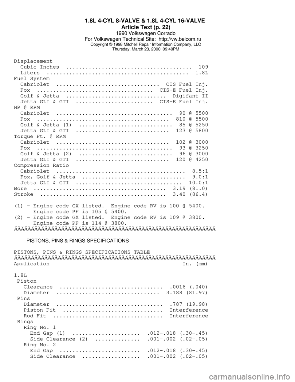
Displacement
Cubic Inches ....................................... 109
Liters ............................................ 1.8L
Fuel System
Cabriolet ................................ CIS Fuel Inj.
Fox .................................... CIS-E Fuel Inj.
Golf & Jetta ............................... Digifant II
Jetta GLI & GTI ........................ CIS-E Fuel Inj.
HP @ RPM
Cabriolet .................................... 90 @ 5500
Fox ......................................... 810 @ 5500
Golf & Jetta (1) ............................. 85 @ 5250
Jetta GLI & GTI ............................. 123 @ 5800
Torque Ft. @ RPM
Cabriolet ................................... 102 @ 3000
Fox .......................................... 93 @ 3250
Golf & Jetta (2) ............................. 96 @ 3000
Jetta GLI & GTI ............................. 120 @ 4250
Compression Ratio
Cabriolet ........................................ 8.5:1
Fox, Golf & Jetta ................................ 9.0:1
Jetta GLI & GTI ................................. 10.0:1
Bore ......................................... 3.19 (81.0)
Stroke ....................................... 3.40 (86.4)
(1) - Engine code GX listed. Engine code RV is 100 @ 5400.
Engine code PF is 105 @ 5400.
(2) - Engine code GX listed. Engine code RV is 109 @ 3800.
Engine code PF is 114 @ 3800.ÄÄÄÄÄÄÄÄÄÄÄÄÄÄÄÄÄÄÄÄÄÄÄÄÄÄÄÄÄÄÄÄÄÄÄÄÄÄÄÄÄÄÄÄÄÄÄÄÄÄÄÄÄÄÄÄÄÄÄÄ PISTONS, PINS & RINGS SPECIFICATIONS
PISTONS, PINS & RINGS SPECIFICATIONS TABLE
ÄÄÄÄÄÄÄÄÄÄÄÄÄÄÄÄÄÄÄÄÄÄÄÄÄÄÄÄÄÄÄÄÄÄÄÄÄÄÄÄÄÄÄÄÄÄÄÄÄÄÄÄÄÄÄÄÄÄÄÄApplication In. (mm)
1.8L
Piston
Clearance ................................ .0016 (.040)
Diameter ................................ 3.188 (81.97)
Pins
Diameter ................................. .787 (19.98)
Piston Fit ............................... Interference
Rod Fit .................................. Interference
Rings
Ring No. 1
End Gap (1) ..................... .012-.018 (.30-.45)
Side Clearance (2) .............. .001-.002 (.02-.05)
Ring No. 2
End Gap ......................... .012-.018 (.30-.45)
Side Clearance .................. .001-.002 (.02-.05)
Page 388 of 906

ABBREVIATIONS
Article Text (p. 11)
1990 Volkswagen Corrado
For Volkswagen Technical Site: http://vw.belcom.ru
Copyright © 1998 Mitchell Repair Information Company, LLC
Thursday, March 23, 2000 09:42PM³SOL or Sol. ³Solenoid ³
³SPFI
³Sequential Port Fuel Injection ³
³SPK
³Spark Control ³
³SPOUT
³Spark Output Signal ³
³SRS
³Supplemental Restraint System (Air Bag) ³
³SS 3/4-4/3
³Shift Solenoid circuit ³
³SSI
³Solid State Ignition ³
³STAR
³Self-Test Automatic Readout ³
³STI
³Self Test Input circuit ³
³STO
³Self-Test Output ³
³SUB-O2
³Sub Oxygen Sensor ³
³Sen. or Sens.
³Sensor ³
³Sol.
³Solenoid ³
³Sprchg.
³Supercharger ³
³Strg.
³Steering ³
³Susp.
³Suspension ³
³Sw.
³Switch ³
³Sys.
³System ³
ÀÄÄÄÄÄÄÄÄÄÄÄÄÄÄÄÄÄÁÄÄÄÄÄÄÄÄÄÄÄÄÄÄÄÄÄÄÄÄÄÄÄÄÄÄÄÄÄÄÄÄÄÄÄÄÄÄÄÄÄÄÄÄÄÄÄÄÄÄÙ "T" ABBREVIATION TABLE
"T" ABBREVIATION TABLE
ÚÄÄÄÄÄÄÄÄÄÄÄÄÄÄÄÄÄÂÄÄÄÄÄÄÄÄÄÄÄÄÄÄÄÄÄÄÄÄÄÄÄÄÄÄÄÄÄÄÄÄÄÄÄÄÄÄÄÄÄÄÄÄÄÄÄÄÄÄ¿
³ABBREVIATION
³DEFINITION ³
ÃÄÄÄÄÄÄÄÄÄÄÄÄÄÄÄÄÄÅÄÄÄÄÄÄÄÄÄÄÄÄÄÄÄÄÄÄÄÄÄÄÄÄÄÄÄÄÄÄÄÄÄÄÄÄÄÄÄÄÄÄÄÄÄÄÄÄÄÄ´
³T.V.
³Throttle Valve ³
³TAB
³Thermactor Air By-Pass ³
³TAC
³Thermostatic Air Cleaner ³
³TAD
³Thermactor Air Diverter ³
³TAN
³Tan ³
³TBI
³Throttle Body Injection ³
³TCC
³Torque Converter Clutch ³
³TCCS
³Toyota Computer Control System ³
³TDC
³Top Dead Center ³
³TDCL
³Total Diagnostic Communication Link ³
³TFI
³Thick Film Ignition system ³
³TGS
³Top Gear Switch (cancels SIL in top gear) ³
³THERMAC
³Thermostatic Air Cleaner ³
³THS
³Transmission Hydraulic Switch ³
³TP/TPS
³Throttle Position Sensor ³
³TPI
³Tuned Port Injection ³
³TPS
³Throttle Position Sensor/Switch ³
³TS
³Temperature Sensor ³
³TSB
³Technical Service Bulletin ³
³TTS
³Transmission Temperature Switch ³
³TV
³Thermovalve ³
³TWC
³Three-Way Catalyst ³
³Temp.
³Temperature ³
³Trans.
³Transaxle/Transmission ³
ÀÄÄÄÄÄÄÄÄÄÄÄÄÄÄÄÄÄÁÄÄÄÄÄÄÄÄÄÄÄÄÄÄÄÄÄÄÄÄÄÄÄÄÄÄÄÄÄÄÄÄÄÄÄÄÄÄÄÄÄÄÄÄÄÄÄÄÄÄÙ
Page 400 of 906

ABBREVIATIONS
Article Text (p. 11)
1990 Volkswagen Corrado
For Volkswagen Technical Site: http://vw.belcom.ru
Copyright © 1998 Mitchell Repair Information Company, LLC
Thursday, March 23, 2000 09:42PM³SIR ³Supplemental Inflatable Restraint ³
³SMEC
³Single Module Engine Controller ³
³SOHC
³Single Overhead Cam ³
³SOL or Sol.
³Solenoid ³
³SPFI
³Sequential Port Fuel Injection ³
³SPK
³Spark Control ³
³SPOUT
³Spark Output Signal ³
³SRS
³Supplemental Restraint System (Air Bag) ³
³SS 3/4-4/3
³Shift Solenoid circuit ³
³SSI
³Solid State Ignition ³
³STAR
³Self-Test Automatic Readout ³
³STI
³Self Test Input circuit ³
³STO
³Self-Test Output ³
³SUB-O2
³Sub Oxygen Sensor ³
³Sen. or Sens.
³Sensor ³
³Sol.
³Solenoid ³
³Sprchg.
³Supercharger ³
³Strg.
³Steering ³
³Susp.
³Suspension ³
³Sw.
³Switch ³
³Sys.
³System ³
ÀÄÄÄÄÄÄÄÄÄÄÄÄÄÄÄÄÄÁÄÄÄÄÄÄÄÄÄÄÄÄÄÄÄÄÄÄÄÄÄÄÄÄÄÄÄÄÄÄÄÄÄÄÄÄÄÄÄÄÄÄÄÄÄÄÄÄÄÄÙ "T" ABBREVIATION TABLE
"T" ABBREVIATION TABLE
ÚÄÄÄÄÄÄÄÄÄÄÄÄÄÄÄÄÄÂÄÄÄÄÄÄÄÄÄÄÄÄÄÄÄÄÄÄÄÄÄÄÄÄÄÄÄÄÄÄÄÄÄÄÄÄÄÄÄÄÄÄÄÄÄÄÄÄÄÄ¿
³ABBREVIATION
³DEFINITION ³
ÃÄÄÄÄÄÄÄÄÄÄÄÄÄÄÄÄÄÅÄÄÄÄÄÄÄÄÄÄÄÄÄÄÄÄÄÄÄÄÄÄÄÄÄÄÄÄÄÄÄÄÄÄÄÄÄÄÄÄÄÄÄÄÄÄÄÄÄÄ´
³T.V.
³Throttle Valve ³
³TAB
³Thermactor Air By-Pass ³
³TAC
³Thermostatic Air Cleaner ³
³TAD
³Thermactor Air Diverter ³
³TAN
³Tan ³
³TBI
³Throttle Body Injection ³
³TCC
³Torque Converter Clutch ³
³TCCS
³Toyota Computer Control System ³
³TDC
³Top Dead Center ³
³TDCL
³Total Diagnostic Communication Link ³
³TFI
³Thick Film Ignition system ³
³TGS
³Top Gear Switch (cancels SIL in top gear) ³
³THERMAC
³Thermostatic Air Cleaner ³
³THS
³Transmission Hydraulic Switch ³
³TP/TPS
³Throttle Position Sensor ³
³TPI
³Tuned Port Injection ³
³TPS
³Throttle Position Sensor/Switch ³
³TS
³Temperature Sensor ³
³TSB
³Technical Service Bulletin ³
³TTS
³Transmission Temperature Switch ³
³TV
³Thermovalve ³
³TWC
³Three-Way Catalyst ³
³Temp.
³Temperature ³
Page 419 of 906
ANTI-LOCK BRAKE SYSTEM
Article Text (p. 11)
1990 Volkswagen Corrado
For Volkswagen Technical Site: http://vw.belcom.ru
Copyright © 1998 Mitchell Repair Information Company, LLC
Thursday, March 23, 2000 09:42PM
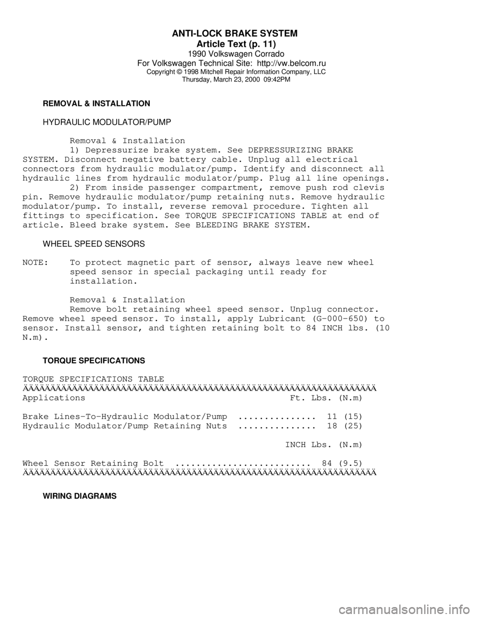
REMOVAL & INSTALLATION
HYDRAULIC MODULATOR/PUMP
Removal & Installation
1) Depressurize brake system. See DEPRESSURIZING BRAKE
SYSTEM. Disconnect negative battery cable. Unplug all electrical
connectors from hydraulic modulator/pump. Identify and disconnect all
hydraulic lines from hydraulic modulator/pump. Plug all line openings.
2) From inside passenger compartment, remove push rod clevis
pin. Remove hydraulic modulator/pump retaining nuts. Remove hydraulic
modulator/pump. To install, reverse removal procedure. Tighten all
fittings to specification. See TORQUE SPECIFICATIONS TABLE at end of
article. Bleed brake system. See BLEEDING BRAKE SYSTEM.
WHEEL SPEED SENSORS
NOTE: To protect magnetic part of sensor, always leave new wheel
speed sensor in special packaging until ready for
installation.
Removal & Installation
Remove bolt retaining wheel speed sensor. Unplug connector.
Remove wheel speed sensor. To install, apply Lubricant (G-000-650) to
sensor. Install sensor, and tighten retaining bolt to 84 INCH lbs. (10
N.m).
TORQUE SPECIFICATIONS
TORQUE SPECIFICATIONS TABLEÄÄÄÄÄÄÄÄÄÄÄÄÄÄÄÄÄÄÄÄÄÄÄÄÄÄÄÄÄÄÄÄÄÄÄÄÄÄÄÄÄÄÄÄÄÄÄÄÄÄÄÄÄÄÄÄÄÄÄÄÄÄÄÄÄApplications Ft. Lbs. (N.m)
Brake Lines-To-Hydraulic Modulator/Pump ............... 11 (15)
Hydraulic Modulator/Pump Retaining Nuts ............... 18 (25)
INCH Lbs. (N.m)
Wheel Sensor Retaining Bolt .......................... 84 (9.5)
ÄÄÄÄÄÄÄÄÄÄÄÄÄÄÄÄÄÄÄÄÄÄÄÄÄÄÄÄÄÄÄÄÄÄÄÄÄÄÄÄÄÄÄÄÄÄÄÄÄÄÄÄÄÄÄÄÄÄÄÄÄÄÄÄÄ WIRING DIAGRAMS
Page 432 of 906
C - SPECIFICATIONS
Article Text (p. 4)
1990 Volkswagen Corrado
For Volkswagen Technical Site: http://vw.belcom.ru
Copyright © 1998 Mitchell Repair Information Company, LLC
Thursday, March 23, 2000 09:43PM
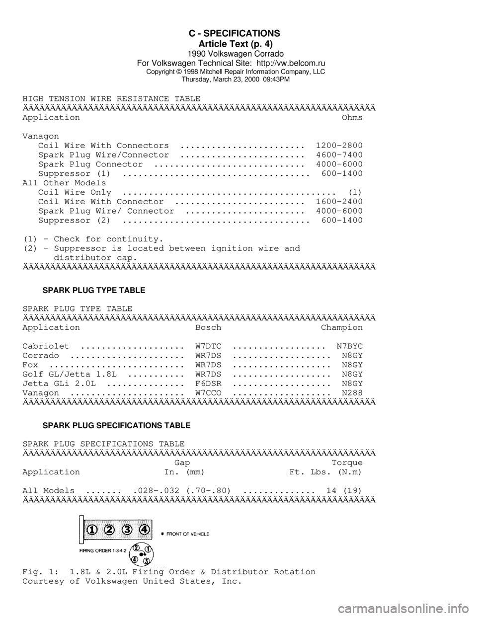
HIGH TENSION WIRE RESISTANCE TABLEÄÄÄÄÄÄÄÄÄÄÄÄÄÄÄÄÄÄÄÄÄÄÄÄÄÄÄÄÄÄÄÄÄÄÄÄÄÄÄÄÄÄÄÄÄÄÄÄÄÄÄÄÄÄÄÄÄÄÄÄÄÄÄÄÄApplication Ohms
Vanagon
Coil Wire With Connectors ........................ 1200-2800
Spark Plug Wire/Connector ........................ 4600-7400
Spark Plug Connector ............................. 4000-6000
Suppressor (1) .................................... 600-1400
All Other Models
Coil Wire Only ......................................... (1)
Coil Wire With Connector ......................... 1600-2400
Spark Plug Wire/ Connector ....................... 4000-6000
Suppressor (2) .................................... 600-1400
(1) - Check for continuity.
(2) - Suppressor is located between ignition wire and
distributor cap.
ÄÄÄÄÄÄÄÄÄÄÄÄÄÄÄÄÄÄÄÄÄÄÄÄÄÄÄÄÄÄÄÄÄÄÄÄÄÄÄÄÄÄÄÄÄÄÄÄÄÄÄÄÄÄÄÄÄÄÄÄÄÄÄÄÄ SPARK PLUG TYPE TABLE
SPARK PLUG TYPE TABLE
ÄÄÄÄÄÄÄÄÄÄÄÄÄÄÄÄÄÄÄÄÄÄÄÄÄÄÄÄÄÄÄÄÄÄÄÄÄÄÄÄÄÄÄÄÄÄÄÄÄÄÄÄÄÄÄÄÄÄÄÄÄÄÄÄÄApplication Bosch Champion
Cabriolet .................... W7DTC .................. N7BYC
Corrado ...................... WR7DS ................... N8GY
Fox .......................... WR7DS ................... N8GY
Golf GL/Jetta 1.8L ........... WR7DS ................... N8GY
Jetta GLi 2.0L ............... F6DSR ................... N8GY
Vanagon ...................... W7CCO ................... N288
ÄÄÄÄÄÄÄÄÄÄÄÄÄÄÄÄÄÄÄÄÄÄÄÄÄÄÄÄÄÄÄÄÄÄÄÄÄÄÄÄÄÄÄÄÄÄÄÄÄÄÄÄÄÄÄÄÄÄÄÄÄÄÄÄÄ SPARK PLUG SPECIFICATIONS TABLE
SPARK PLUG SPECIFICATIONS TABLE
ÄÄÄÄÄÄÄÄÄÄÄÄÄÄÄÄÄÄÄÄÄÄÄÄÄÄÄÄÄÄÄÄÄÄÄÄÄÄÄÄÄÄÄÄÄÄÄÄÄÄÄÄÄÄÄÄÄÄÄÄÄÄÄÄÄ Gap Torque
Application In. (mm) Ft. Lbs. (N.m)
All Models ....... .028-.032 (.70-.80) .............. 14 (19)
ÄÄÄÄÄÄÄÄÄÄÄÄÄÄÄÄÄÄÄÄÄÄÄÄÄÄÄÄÄÄÄÄÄÄÄÄÄÄÄÄÄÄÄÄÄÄÄÄÄÄÄÄÄÄÄÄÄÄÄÄÄÄÄÄÄFig. 1: 1.8L & 2.0L Firing Order & Distributor Rotation
Courtesy of Volkswagen United States, Inc.
Page 514 of 906
ENGINE OVERHAUL PROCEDURES - GENERAL INFORMATION
Article Text (p. 5)
1990 Volkswagen Corrado
For Volkswagen Technical Site: http://vw.belcom.ru
Copyright © 1998 Mitchell Repair Information Company, LLC
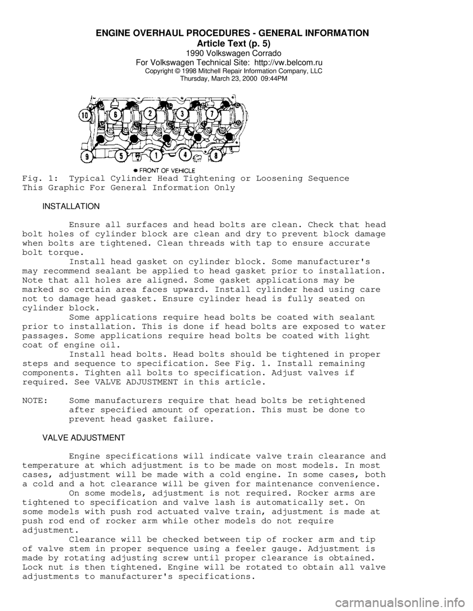
Thursday, March 23, 2000 09:44PMFig. 1: Typical Cylinder Head Tightening or Loosening Sequence
This Graphic For General Information Only
INSTALLATION
Ensure all surfaces and head bolts are clean. Check that head
bolt holes of cylinder block are clean and dry to prevent block damage
when bolts are tightened. Clean threads with tap to ensure accurate
bolt torque.
Install head gasket on cylinder block. Some manufacturer's
may recommend sealant be applied to head gasket prior to installation.
Note that all holes are aligned. Some gasket applications may be
marked so certain area faces upward. Install cylinder head using care
not to damage head gasket. Ensure cylinder head is fully seated on
cylinder block.
Some applications require head bolts be coated with sealant
prior to installation. This is done if head bolts are exposed to water
passages. Some applications require head bolts be coated with light
coat of engine oil.
Install head bolts. Head bolts should be tightened in proper
steps and sequence to specification. See Fig. 1. Install remaining
components. Tighten all bolts to specification. Adjust valves if
required. See VALVE ADJUSTMENT in this article.
NOTE: Some manufacturers require that head bolts be retightened
after specified amount of operation. This must be done to
prevent head gasket failure.
VALVE ADJUSTMENT
Engine specifications will indicate valve train clearance and
temperature at which adjustment is to be made on most models. In most
cases, adjustment will be made with a cold engine. In some cases, both
a cold and a hot clearance will be given for maintenance convenience.
On some models, adjustment is not required. Rocker arms are
tightened to specification and valve lash is automatically set. On
some models with push rod actuated valve train, adjustment is made at
push rod end of rocker arm while other models do not require
adjustment.
Clearance will be checked between tip of rocker arm and tip
of valve stem in proper sequence using a feeler gauge. Adjustment is
made by rotating adjusting screw until proper clearance is obtained.
Lock nut is then tightened. Engine will be rotated to obtain all valve
adjustments to manufacturer's specifications.
Page 534 of 906
ENGINE OVERHAUL PROCEDURES - GENERAL INFORMATION
Article Text (p. 25)
1990 Volkswagen Corrado
For Volkswagen Technical Site: http://vw.belcom.ru
Copyright © 1998 Mitchell Repair Information Company, LLC
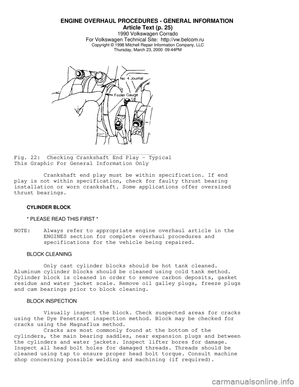
Thursday, March 23, 2000 09:44PMFig. 22: Checking Crankshaft End Play - Typical
This Graphic For General Information Only
Crankshaft end play must be within specification. If end
play is not within specification, check for faulty thrust bearing
installation or worn crankshaft. Some applications offer oversized
thrust bearings.
CYLINDER BLOCK
* PLEASE READ THIS FIRST *
NOTE: Always refer to appropriate engine overhaul article in the
ENGINES section for complete overhaul procedures and
specifications for the vehicle being repaired.
BLOCK CLEANING
Only cast cylinder blocks should be hot tank cleaned.
Aluminum cylinder blocks should be cleaned using cold tank method.
Cylinder block is cleaned in order to remove carbon deposits, gasket
residue and water jacket scale. Remove oil galley plugs, freeze plugs
and cam bearings prior to block cleaning.
BLOCK INSPECTION
Visually inspect the block. Check suspected areas for cracks
using the Dye Penetrant inspection method. Block may be checked for
cracks using the Magnaflux method.
Cracks are most commonly found at the bottom of the
cylinders, the main bearing saddles, near expansion plugs and between
the cylinders and water jackets. Inspect lifter bores for damage.
Inspect all head bolt holes for damaged threads. Threads should be
cleaned using tap to ensure proper head bolt torque. Consult machine
shop concerning possible welding and machining (if required).
Page 598 of 906
I - SYSTEM/COMPONENT TESTS
Article Text (p. 11)
1990 Volkswagen Corrado
For Volkswagen Technical Site: http://vw.belcom.ru
Copyright © 1998 Mitchell Repair Information Company, LLC
Thursday, March 23, 2000 09:46PM
okay, check ground circuit through thermo time switch. Replace thermo
time switch if contact to ground cannot be made.
IDLE CONTROL SYSTEM
NOTE: Knock control is integral in AFC-Digifant II ECU.
KNOCK SENSOR CONTROL UNIT (ALL MODELS EXCEPT VANAGON)
1) Check ignition coil and Hall Effect sender before checking
knock sensor control unit. Remove knock sensor control unit harness
connector. Turn ignition on. Using a voltmeter, check for battery
voltage between terminals No. 3 and No. 5 and terminals No. 6 and No.
3 of knock sensor control unit. Open throttle valve. Voltage should
drop to zero volts.
2) If voltage does not drop to zero volts, check throttle
valve switch (full throttle). Check voltage between terminals No. 8
and No. 3, while fully opening throttle valve. If battery voltage was
not present when throttle fully open, replace throttle valve switch.
See Fig. 13.
3) Remove Hall Effect sender connector and connect voltmeter
to outside terminals. Turn ignition on. There should be 5 volts
present. Turn ignition off. Connect voltmeter between terminals No. 1
(negative) and No. 15 (positive) of ignition coil. Turn ignition on
and touch center terminal of Hall Effect sender briefly to ground.
Voltage should jump momentarily to approximately 2 volts. If voltage
does not jump, replace knock sensor control unit.
KNOCK SENSOR(S)
Before replacing knock sensor, check knock sensor torque and
resistance. Remove knock sensor connector and check resistance between
terminals No. 13 and No. 14. See KNOCK SENSOR TORQUE & RESISTANCE
SPECIFICATION table. If resistance is incorrect, replace knock sensor.
NOTE: Knock sensor mounting bolt torque must be exact. DO NOT use
washers when mounting knock sensor.
KNOCK SENSOR RESISTANCE & TORQUE SPECIFICATIONÄÄÄÄÄÄÄÄÄÄÄÄÄÄÄÄÄÄÄÄÄÄÄÄÄÄÄÄÄÄÄÄÄÄÄÄÄÄÄÄÄÄÄÄÄÄÄÄÄÄÄÄÄÄÄÄÄÄÄÄÄÄÄÄÄÄÄÄÄÄApplication Resistance Ft. Lbs (N.m)
Type I ...................... 300,000 ................ 7-9 (10-12)
Type II .................... Infinite .............. 15-18 (20-25)
ÄÄÄÄÄÄÄÄÄÄÄÄÄÄÄÄÄÄÄÄÄÄÄÄÄÄÄÄÄÄÄÄÄÄÄÄÄÄÄÄÄÄÄÄÄÄÄÄÄÄÄÄÄÄÄÄÄÄÄÄÄÄÄÄÄÄÄÄÄÄ IDLE STABILIZATION SYSTEM (VANAGON)
1) Attach Test Meter (VW 1315/2) and Adapter (US 1119) to
idle stabilization valve. Set meter to milliampere scale. Start
engine. Observe test meter while turning A/C control switch to ON
position. If milliampere reading increases, system is okay.