1990 VOLKSWAGEN CORRADO wheel
[x] Cancel search: wheelPage 749 of 906
STEERING SYSTEM - POWER
Article Text (p. 2)
1990 Volkswagen Corrado
For Volkswagen Technical Site: http://vw.belcom.ru
Copyright © 1998 Mitchell Repair Information Company, LLC
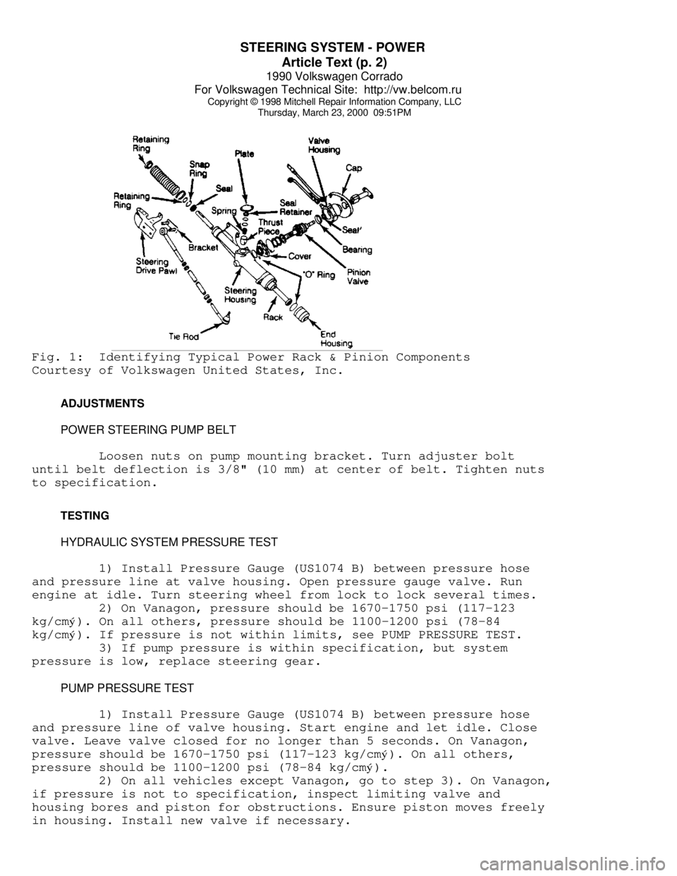
Thursday, March 23, 2000 09:51PMFig. 1: Identifying Typical Power Rack & Pinion Components
Courtesy of Volkswagen United States, Inc.
ADJUSTMENTS
POWER STEERING PUMP BELT
Loosen nuts on pump mounting bracket. Turn adjuster bolt
until belt deflection is 3/8" (10 mm) at center of belt. Tighten nuts
to specification.
TESTING
HYDRAULIC SYSTEM PRESSURE TEST
1) Install Pressure Gauge (US1074 B) between pressure hose
and pressure line at valve housing. Open pressure gauge valve. Run
engine at idle. Turn steering wheel from lock to lock several times.
2) On Vanagon, pressure should be 1670-1750 psi (117-123
kg/cmý). On all others, pressure should be 1100-1200 psi (78-84
kg/cm
ý). If pressure is not within limits, see PUMP PRESSURE TEST.
3) If pump pressure is within specification, but system
pressure is low, replace steering gear.
PUMP PRESSURE TEST
1) Install Pressure Gauge (US1074 B) between pressure hose
and pressure line of valve housing. Start engine and let idle. Close
valve. Leave valve closed for no longer than 5 seconds. On Vanagon,
pressure should be 1670-1750 psi (117-123 kg/cm
ý). On all others,
pressure should be 1100-1200 psi (78-84 kg/cm
ý).
2) On all vehicles except Vanagon, go to step 3). On Vanagon,
if pressure is not to specification, inspect limiting valve and
housing bores and piston for obstructions. Ensure piston moves freely
in housing. Install new valve if necessary.
Page 750 of 906
STEERING SYSTEM - POWER
Article Text (p. 3)
1990 Volkswagen Corrado
For Volkswagen Technical Site: http://vw.belcom.ru
Copyright © 1998 Mitchell Repair Information Company, LLC
Thursday, March 23, 2000 09:51PM
3) If pump pressure is not within specification, replace
pump.
STEERING WHEEL TURNING FORCE
Except Vanagon
Remove steering gear. See POWER RACK & PINION under REMOVAL &
INSTALLATION. Loosen lock nut. Turn adjuster bolt until pinion shaft
can be turned by hand without binding. Hold adjuster bolt in position
while tightening lock nut.
Vanagon
If steering effort is too high, check steering shaft,
steering linkage, "U" joints, and ball joints for binding. If all are
okay, replace steering gear.
REMOVAL & INSTALLATION
POWER STEERING PUMP
Removal
Remove alternator and pump belts. Disconnect hydraulic lines
from pump. Cap lines to prevent contamination. Remove bracket bolts.
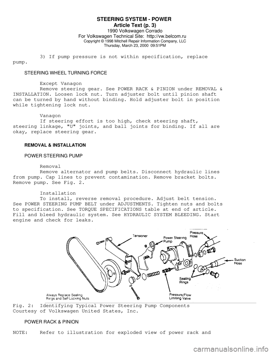
Remove pump. See Fig. 2.
Installation
To install, reverse removal procedure. Adjust belt tension.
See POWER STEERING PUMP BELT under ADJUSTMENTS. Tighten nuts and bolts
to specification. See TORQUE SPECIFICATIONS table at end of article.
Fill and bleed hydraulic system. See HYDRAULIC SYSTEM BLEEDING. Start
engine and check for leaks.Fig. 2: Identifying Typical Power Steering Pump Components
Courtesy of Volkswagen United States, Inc.
POWER RACK & PINION
NOTE: Refer to illustration for exploded view of power rack and
Page 751 of 906

STEERING SYSTEM - POWER
Article Text (p. 4)
1990 Volkswagen Corrado
For Volkswagen Technical Site: http://vw.belcom.ru
Copyright © 1998 Mitchell Repair Information Company, LLC
Thursday, March 23, 2000 09:51PM
pinion components. See Fig. 1.
Removal (Cabriolet)
1) Remove pressure line from pump. Drain fluid from pump and
line. Disconnect tie rod ends from steering knuckles. Remove
transmission mount and bracket. Remove exhaust manifold.
2) Remove hydraulic lines from steering gear. Plug openings.
Remove shift linkage from steering gear (if equipped). Remove ground
wire. Disconnect pinion shaft at "U" joint. Remove retaining bolts and
steering gear.
Removal (Corrado)
1) Disconnect return line from pump. Drain fluid from pump
and line. Disconnect tie rod ends from steering knuckles.
2) Remove lock bolt at "U" joint. Remove steering gear
retaining bolts. Disconnect hydraulic lines at steering gear. Plug
openings.
3) Support engine and transmission. Remove subframe bolts.
Remove steering gear.
Removal (Golf, GTI & Jetta)
1) Disconnect return line from pump. Drain fluid from pump
and line. Disconnect tie rod ends from steering knuckles.
2) Remove shift linkage from steering gear (if equipped).
Disconnect pinion shaft at "U" joint. Disconnect hydraulic lines from
steering gear. Plug openings. Remove retaining bolts.
3) Support engine and transmission with Engine Support (10-
222A). Remove left transmission mount bolts. Loosen right transmission
mount bolts. Remove steering gear.
Removal (Passat)
1) Disconnect return line from pump. Drain fluid from pump
and line. Disconnect tie rod ends from steering knuckles.
2) Support engine and transmission with Engine Support (10-
222A and 10-222A/1). Remove steering gear boot. Remove transmission
mount bolts. Lower engine/transmission sufficiently to separate
steering shaft halves.
3) Disconnect hydraulic lines from steering gear. Plug
openings. Remove retaining nuts and steering gear.
Removal (Vanagon)
1) Removal and installation information is not available from
manufacturer.
Installation (All Models)
Reverse removal procedure to install. Tighten nuts and bolts
to specification. See TORQUE SPECIFICATIONS table at end of article.
Fill and bleed hydraulic system. See HYDRAULIC SYSTEM BLEEDING. Check
wheel alignment. See appropriate WHEEL ALIGNMENT SPECIFICATIONS &
PROCEDURES article in the WHEEL ALIGNMENT section:
* WHEEL ALIGNMENT SPECIFICATIONS & PROCEDURES - (1990 - All
Page 752 of 906

STEERING SYSTEM - POWER
Article Text (p. 5)
1990 Volkswagen Corrado
For Volkswagen Technical Site: http://vw.belcom.ru
Copyright © 1998 Mitchell Repair Information Company, LLC
Thursday, March 23, 2000 09:51PM
models except Corrado & Passat)
* WHEEL ALIGNMENT SPECIFICATIONS & PROCEDURES - (1990 -
Corrado & Passat)
* WHEEL ALIGNMENT SPECIFICATIONS & PROCEDURES - 1991
* WHEEL ALIGNMENT SPECIFICATIONS & PROCEDURES - 1992
OVERHAUL
Manufacturer recommends that power steering pump and steering
gear be replaced, rather than be repaired.
TORQUE SPECIFICATIONS
TORQUE SPECIFICATIONS TABLEÄÄÄÄÄÄÄÄÄÄÄÄÄÄÄÄÄÄÄÄÄÄÄÄÄÄÄÄÄÄÄÄÄÄÄÄÄÄÄÄÄÄÄÄÄÄÄÄÄÄÄÄÄÄÄÄÄÄÄÄApplication Ft. Lbs. (N.m)
End Housing Bolt ................................. 37 (50)
Power Steering Pump Bolt ......................... 18 (25)
Pressure-Flow Limiting Valve Cap ................. 42 (57)
Pressure Line Fitting ............................ 29 (39)
Return Line Fitting
On Pump ........................................ 29 (39)
On Valve Housing ............................... 22 (30)
Steering Gear Adjuster Lock Nut ..................... (1)
Steering Gear Retaining Bolt ...................... 22 (30
Subframe Bolt
Long .......................................... 96 (130)
Short .......................................... 59 (80)
Tie Rod-to-Steering Arm .......................... 32 (44)
Valve Housing Bolt ............................... 15 (20)
(1) - Not specified by manufacturer.
ÄÄÄÄÄÄÄÄÄÄÄÄÄÄÄÄÄÄÄÄÄÄÄÄÄÄÄÄÄÄÄÄÄÄÄÄÄÄÄÄÄÄÄÄÄÄÄÄÄÄÄÄÄÄÄÄÄÄÄÄEND OF ARTICLE
Page 753 of 906
SUSPENSION - FRONT
Article Text
1990 Volkswagen Corrado
For Volkswagen Technical Site: http://vw.belcom.ru
Copyright © 1998 Mitchell Repair Information Company, LLC
Thursday, March 23, 2000 09:51PM
ARTICLE BEGINNING
1990-92 SUSPENSION
Volkswagen Front
1990-92 Passat
1991-92 Cabriolet, Corrado, Golf, GTI, Jetta
DESCRIPTION
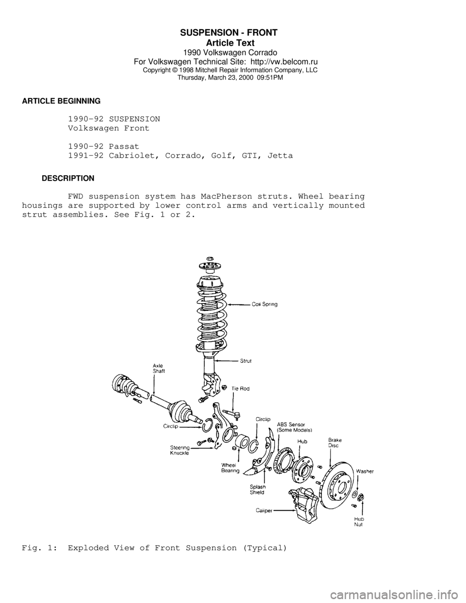
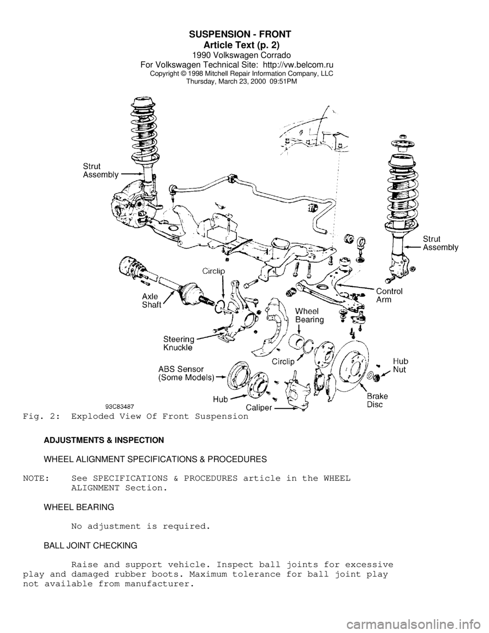
FWD suspension system has MacPherson struts. Wheel bearing
housings are supported by lower control arms and vertically mounted
strut assemblies. See Fig. 1 or 2.Fig. 1: Exploded View of Front Suspension (Typical)
Page 754 of 906
SUSPENSION - FRONT
Article Text (p. 2)
1990 Volkswagen Corrado
For Volkswagen Technical Site: http://vw.belcom.ru
Copyright © 1998 Mitchell Repair Information Company, LLC
Thursday, March 23, 2000 09:51PMFig. 2: Exploded View Of Front Suspension
ADJUSTMENTS & INSPECTION
WHEEL ALIGNMENT SPECIFICATIONS & PROCEDURES
NOTE: See SPECIFICATIONS & PROCEDURES article in the WHEEL
ALIGNMENT Section.
WHEEL BEARING
No adjustment is required.
BALL JOINT CHECKING
Raise and support vehicle. Inspect ball joints for excessive
play and damaged rubber boots. Maximum tolerance for ball joint play
not available from manufacturer.
Page 755 of 906
SUSPENSION - FRONT
Article Text (p. 3)
1990 Volkswagen Corrado
For Volkswagen Technical Site: http://vw.belcom.ru
Copyright © 1998 Mitchell Repair Information Company, LLC
Thursday, March 23, 2000 09:51PM
REMOVAL & INSTALLATION
HUB & KNUCKLE ASSEMBLY
Use exploded view illustration when removing or installing
hub and knuckle assembly. See Fig. 1 or 2.
LOWER CONTROL ARM & BALL JOINT
Removal
1) Raise and support vehicle. Remove bolt retaining ball
joint at wheel bearing housing. Force ball joint from of housing.
Leave control arm hanging in mounts at subframe.
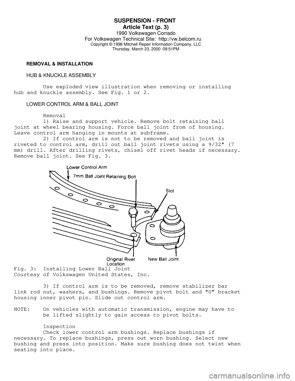
2) If control arm is not to be removed and ball joint is
riveted to control arm, drill out ball joint rivets using a 9/32" (7
mm) drill. After drilling rivets, chisel off rivet heads if necessary.
Remove ball joint. See Fig. 3.Fig. 3: Installing Lower Ball Joint
Courtesy of Volkswagen United States, Inc.
3) If control arm is to be removed, remove stabilizer bar
link rod nut, washers, and bushings. Remove pivot bolt and "U" bracket
housing inner pivot pin. Slide out control arm.
NOTE: On vehicles with automatic transmission, engine may have to
be lifted slightly to gain access to pivot bolts.
Inspection
Check lower control arm bushings. Replace bushings if
necessary. To replace bushings, press out worn bushing. Select new
bushing and press into position. Make sure bushing does not twist when
seating into place.
Page 756 of 906

SUSPENSION - FRONT
Article Text (p. 4)
1990 Volkswagen Corrado
For Volkswagen Technical Site: http://vw.belcom.ru
Copyright © 1998 Mitchell Repair Information Company, LLC
Thursday, March 23, 2000 09:51PM
Installation
Slide new ball joint into slot in control arm. Install and
tighten ball joint retaining bolts. Install lower control arm to
subframe. Install ball joint into wheel bearing housing. To complete
installation, reverse removal procedure. Tighten control arm bolts
with vehicle on ground. Tighten all bolts and nuts to specification.
See TORQUE SPECIFICATIONS TABLE at end of article. Check wheel
alignment. See SPECIFICATIONS & PROCEDURES article in the WHEEL
ALIGNMENT Section.
STRUT ASSEMBLY
Removal
1) Raise and support vehicle. Remove wheel assembly. Remove
and support caliper assembly out of work area. Remove bolts which
retain strut to wheel bearing housing. Note top bolt is used to adjust
front wheel camber.
2) Support front suspension arm and related components. Pry
suspension strut from wheel bearing housing. Working inside engine
compartment, remove upper strut retaining nuts. Remove strut.
Installation
To install, reverse removal procedure. Tighten bolts and nuts
to specification. See TORQUE SPECIFICATIONS TABLE at end of article.
Check wheel alignment. See SPECIFICATIONS & PROCEDURES article in the
WHEEL ALIGNMENT Section.
FRONT SUSPENSION ASSEMBLY
Removal
1) Raise vehicle and support at center with safety stands.
Disconnect brake line and plug openings. Leave flex line in place.
Remove stabilizer link rod nut, bushings and washers.
2) Remove tie rod nut. Separate tie rod from wheel bearing
housing. Remove bolts retaining inner portion of constant velocity
joint to transaxle drive flange.
3) Remove lower control arm front pivot bolt. Remove bolts
retaining "U" shaped bracket holding control arm rear pivot.
NOTE: On vehicles with automatic transmission, engine may have to
be lifted slightly to gain access to pivot bolts.
4) Support suspension assembly being removed. Remove upper
strut retaining nuts. Remove suspension assembly from vehicle.
Installation
To install, reverse removal procedure. Make sure convex side
of thrust washer faces pivot bolt head. Tighten bolts and nuts to
specification. Check wheel alignment.See SPECIFICATIONS & PROCEDURES
article in the WHEEL ALIGNMENT Section.
WHEEL BEARING