1990 VOLKSWAGEN CORRADO wheel bolt torque
[x] Cancel search: wheel bolt torquePage 419 of 906
ANTI-LOCK BRAKE SYSTEM
Article Text (p. 11)
1990 Volkswagen Corrado
For Volkswagen Technical Site: http://vw.belcom.ru
Copyright © 1998 Mitchell Repair Information Company, LLC
Thursday, March 23, 2000 09:42PM
REMOVAL & INSTALLATION
HYDRAULIC MODULATOR/PUMP
Removal & Installation
1) Depressurize brake system. See DEPRESSURIZING BRAKE
SYSTEM. Disconnect negative battery cable. Unplug all electrical
connectors from hydraulic modulator/pump. Identify and disconnect all
hydraulic lines from hydraulic modulator/pump. Plug all line openings.
2) From inside passenger compartment, remove push rod clevis
pin. Remove hydraulic modulator/pump retaining nuts. Remove hydraulic
modulator/pump. To install, reverse removal procedure. Tighten all
fittings to specification. See TORQUE SPECIFICATIONS TABLE at end of
article. Bleed brake system. See BLEEDING BRAKE SYSTEM.
WHEEL SPEED SENSORS
NOTE: To protect magnetic part of sensor, always leave new wheel
speed sensor in special packaging until ready for
installation.
Removal & Installation
Remove bolt retaining wheel speed sensor. Unplug connector.
Remove wheel speed sensor. To install, apply Lubricant (G-000-650) to
sensor. Install sensor, and tighten retaining bolt to 84 INCH lbs. (10
N.m).
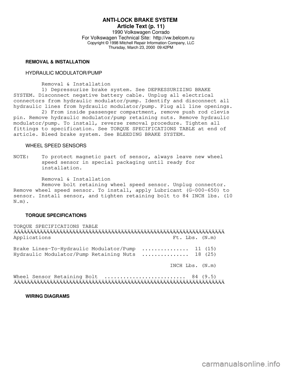
TORQUE SPECIFICATIONS
TORQUE SPECIFICATIONS TABLEÄÄÄÄÄÄÄÄÄÄÄÄÄÄÄÄÄÄÄÄÄÄÄÄÄÄÄÄÄÄÄÄÄÄÄÄÄÄÄÄÄÄÄÄÄÄÄÄÄÄÄÄÄÄÄÄÄÄÄÄÄÄÄÄÄApplications Ft. Lbs. (N.m)
Brake Lines-To-Hydraulic Modulator/Pump ............... 11 (15)
Hydraulic Modulator/Pump Retaining Nuts ............... 18 (25)
INCH Lbs. (N.m)
Wheel Sensor Retaining Bolt .......................... 84 (9.5)
ÄÄÄÄÄÄÄÄÄÄÄÄÄÄÄÄÄÄÄÄÄÄÄÄÄÄÄÄÄÄÄÄÄÄÄÄÄÄÄÄÄÄÄÄÄÄÄÄÄÄÄÄÄÄÄÄÄÄÄÄÄÄÄÄÄ WIRING DIAGRAMS
Page 739 of 906
STEERING COLUMN
Article Text (p. 5)
1990 Volkswagen Corrado
For Volkswagen Technical Site: http://vw.belcom.ru
Copyright © 1998 Mitchell Repair Information Company, LLC
Thursday, March 23, 2000 09:51PM
Check upper bracket for damage and upper bearing for smooth
rotation. Check shafts for signs of bending, damaged splines, or
damaged "U" joints. Check column tube for bending or other damage.
Repair or replace components as necessary.
Reassembly
Press in steering shaft and new bearings. DO NOT use more
than 200 lbs. (90 kg) force to press shaft and bearings into column
tube.
"U" JOINT SHAFT
Disassembly
1) Remove pinch bolt that connects lower end of "U" joint
shaft to steering gear pinion shaft. See Fig. 2. Separate manual
gearshift linkage from steering box. Remove steering gear retaining
nuts.
2) Pull box down to separate from lower "U" joint. Remove
rubber boot from lower "U" joint. Remove upper "U" joint pinch bolt.
Pull down joint and remove shaft with "U" joints.
Inspection
Inspect "U" joints for wear or excessive play. If abnormal
wear or play exists, replace as necessary.
Reassembly
1) Fit "U" joint to steering shaft. Align steering shaft
notch with lower "U" joint slot. Install boot and damping grommet. Fit
steering box to frame while guiding pinion shaft into lower "U" joint.
2) Hand-tighten steering gear retaining nuts. Place wheels in
straight-ahead position. Align pinion shaft and "U" joint. Tighten
pinch bolt. Tighten steering gear retaining nuts. Connect gearshift
linkage. Check linkage for smooth operation.
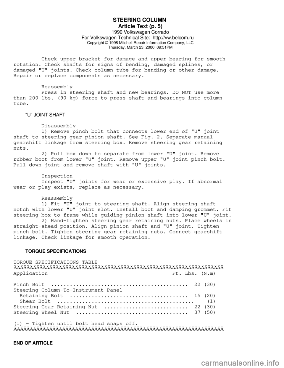
TORQUE SPECIFICATIONS
TORQUE SPECIFICATIONS TABLEÄÄÄÄÄÄÄÄÄÄÄÄÄÄÄÄÄÄÄÄÄÄÄÄÄÄÄÄÄÄÄÄÄÄÄÄÄÄÄÄÄÄÄÄÄÄÄÄÄÄÄÄÄÄÄÄÄÄÄÄÄÄÄÄÄApplication Ft. Lbs. (N.m)
Pinch Bolt ............................................ 22 (30)
Steering Column-To-Instrument Panel
Retaining Bolt ...................................... 15 (20)
Shear Bolt ............................................ (1)
Steering Gear Retaining Nut ........................... 22 (30)
Steering Wheel Nut .................................... 37 (50)
(1) - Tighten until bolt head snaps off.
ÄÄÄÄÄÄÄÄÄÄÄÄÄÄÄÄÄÄÄÄÄÄÄÄÄÄÄÄÄÄÄÄÄÄÄÄÄÄÄÄÄÄÄÄÄÄÄÄÄÄÄÄÄÄÄÄÄÄÄÄÄÄÄÄÄEND OF ARTICLE
Page 745 of 906
STEERING COLUMN SWITCHES
Article Text (p. 6)
1990 Volkswagen Corrado
For Volkswagen Technical Site: http://vw.belcom.ru
Copyright © 1998 Mitchell Repair Information Company, LLC
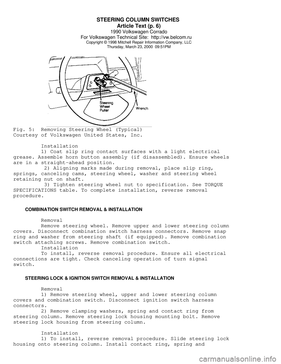
Thursday, March 23, 2000 09:51PMFig. 5: Removing Steering Wheel (Typical)
Courtesy of Volkswagen United States, Inc.
Installation
1) Coat slip ring contact surfaces with a light electrical
grease. Assemble horn button assembly (if disassembled). Ensure wheels
are in a straight-ahead position.
2) Aligning marks made during removal, place slip ring,
springs, canceling cams, steering wheel, washer and steering wheel
retaining nut on shaft.
3) Tighten steering wheel nut to specification. See TORQUE
SPECIFICATIONS table. To complete installation, reverse removal
procedure.
COMBINATION SWITCH REMOVAL & INSTALLATION
Removal
Remove steering wheel. Remove upper and lower steering column
covers. Disconnect combination switch harness connectors. Remove snap
ring and washer from steering shaft (if equipped). Remove combination
switch attaching screws. Remove combination switch.
Installation
To install, reverse removal procedure. Ensure all electrical
connections are tight. Check canceling operation of turn signal
switch.
STEERING LOCK & IGNITION SWITCH REMOVAL & INSTALLATION
Removal
1) Remove steering wheel, upper and lower steering column
covers and combination switch. Disconnect ignition switch harness
connectors.
2) Remove clamping washers, spring and contact ring from
steering column. Remove steering lock housing mounting bolt. Remove
steering lock housing from steering column.
Installation
1) To install, reverse removal procedure. Slide steering lock
housing onto steering column. Install contact ring, spring and
Page 750 of 906
STEERING SYSTEM - POWER
Article Text (p. 3)
1990 Volkswagen Corrado
For Volkswagen Technical Site: http://vw.belcom.ru
Copyright © 1998 Mitchell Repair Information Company, LLC
Thursday, March 23, 2000 09:51PM
3) If pump pressure is not within specification, replace
pump.
STEERING WHEEL TURNING FORCE
Except Vanagon
Remove steering gear. See POWER RACK & PINION under REMOVAL &
INSTALLATION. Loosen lock nut. Turn adjuster bolt until pinion shaft
can be turned by hand without binding. Hold adjuster bolt in position
while tightening lock nut.
Vanagon
If steering effort is too high, check steering shaft,
steering linkage, "U" joints, and ball joints for binding. If all are
okay, replace steering gear.
REMOVAL & INSTALLATION
POWER STEERING PUMP
Removal
Remove alternator and pump belts. Disconnect hydraulic lines
from pump. Cap lines to prevent contamination. Remove bracket bolts.
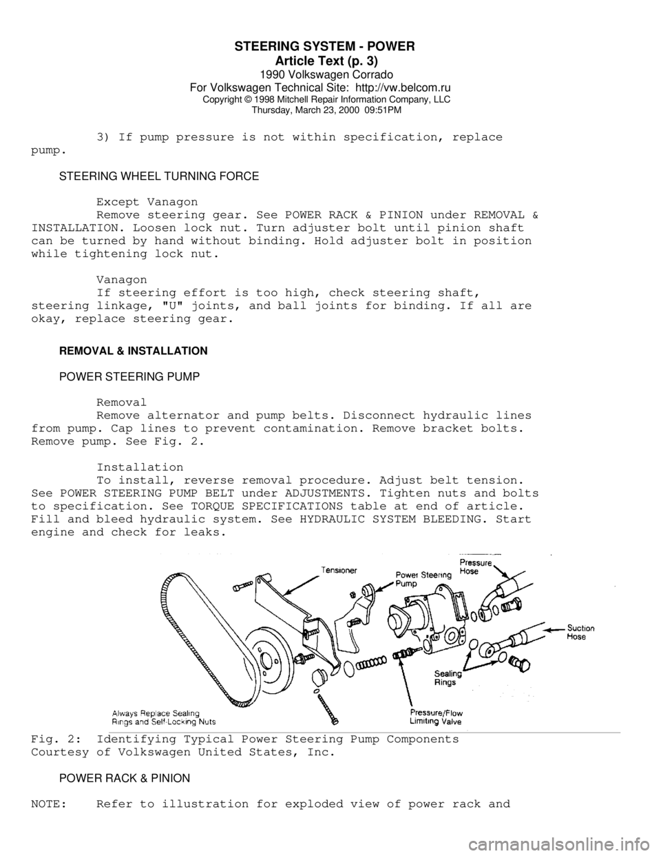
Remove pump. See Fig. 2.
Installation
To install, reverse removal procedure. Adjust belt tension.
See POWER STEERING PUMP BELT under ADJUSTMENTS. Tighten nuts and bolts
to specification. See TORQUE SPECIFICATIONS table at end of article.
Fill and bleed hydraulic system. See HYDRAULIC SYSTEM BLEEDING. Start
engine and check for leaks.Fig. 2: Identifying Typical Power Steering Pump Components
Courtesy of Volkswagen United States, Inc.
POWER RACK & PINION
NOTE: Refer to illustration for exploded view of power rack and
Page 751 of 906
STEERING SYSTEM - POWER
Article Text (p. 4)
1990 Volkswagen Corrado
For Volkswagen Technical Site: http://vw.belcom.ru
Copyright © 1998 Mitchell Repair Information Company, LLC
Thursday, March 23, 2000 09:51PM
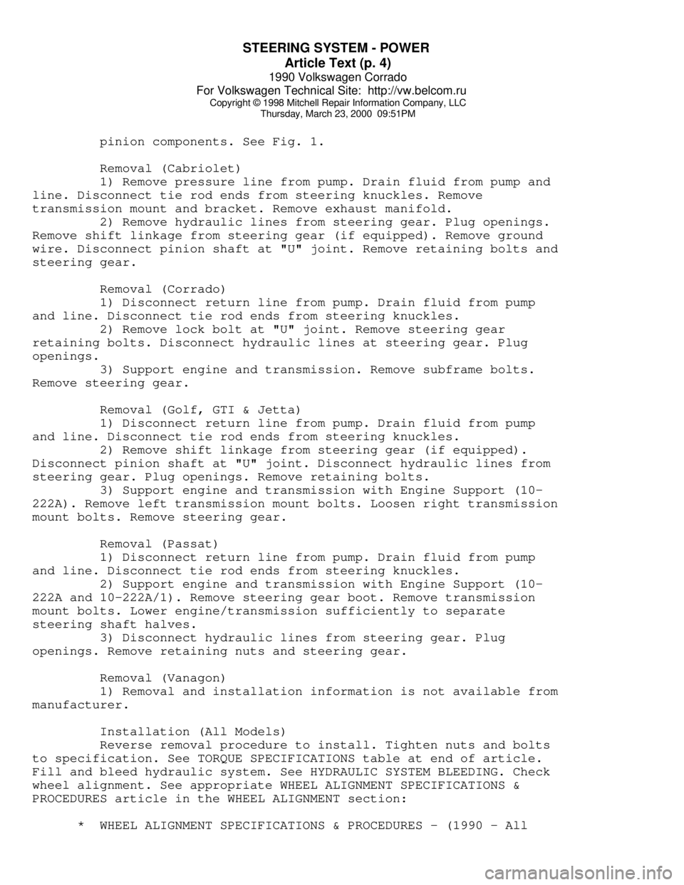
pinion components. See Fig. 1.
Removal (Cabriolet)
1) Remove pressure line from pump. Drain fluid from pump and
line. Disconnect tie rod ends from steering knuckles. Remove
transmission mount and bracket. Remove exhaust manifold.
2) Remove hydraulic lines from steering gear. Plug openings.
Remove shift linkage from steering gear (if equipped). Remove ground
wire. Disconnect pinion shaft at "U" joint. Remove retaining bolts and
steering gear.
Removal (Corrado)
1) Disconnect return line from pump. Drain fluid from pump
and line. Disconnect tie rod ends from steering knuckles.
2) Remove lock bolt at "U" joint. Remove steering gear
retaining bolts. Disconnect hydraulic lines at steering gear. Plug
openings.
3) Support engine and transmission. Remove subframe bolts.
Remove steering gear.
Removal (Golf, GTI & Jetta)
1) Disconnect return line from pump. Drain fluid from pump
and line. Disconnect tie rod ends from steering knuckles.
2) Remove shift linkage from steering gear (if equipped).
Disconnect pinion shaft at "U" joint. Disconnect hydraulic lines from
steering gear. Plug openings. Remove retaining bolts.
3) Support engine and transmission with Engine Support (10-
222A). Remove left transmission mount bolts. Loosen right transmission
mount bolts. Remove steering gear.
Removal (Passat)
1) Disconnect return line from pump. Drain fluid from pump
and line. Disconnect tie rod ends from steering knuckles.
2) Support engine and transmission with Engine Support (10-
222A and 10-222A/1). Remove steering gear boot. Remove transmission
mount bolts. Lower engine/transmission sufficiently to separate
steering shaft halves.
3) Disconnect hydraulic lines from steering gear. Plug
openings. Remove retaining nuts and steering gear.
Removal (Vanagon)
1) Removal and installation information is not available from
manufacturer.
Installation (All Models)
Reverse removal procedure to install. Tighten nuts and bolts
to specification. See TORQUE SPECIFICATIONS table at end of article.
Fill and bleed hydraulic system. See HYDRAULIC SYSTEM BLEEDING. Check
wheel alignment. See appropriate WHEEL ALIGNMENT SPECIFICATIONS &
PROCEDURES article in the WHEEL ALIGNMENT section:
* WHEEL ALIGNMENT SPECIFICATIONS & PROCEDURES - (1990 - All
Page 752 of 906
STEERING SYSTEM - POWER
Article Text (p. 5)
1990 Volkswagen Corrado
For Volkswagen Technical Site: http://vw.belcom.ru
Copyright © 1998 Mitchell Repair Information Company, LLC
Thursday, March 23, 2000 09:51PM
models except Corrado & Passat)
* WHEEL ALIGNMENT SPECIFICATIONS & PROCEDURES - (1990 -
Corrado & Passat)
* WHEEL ALIGNMENT SPECIFICATIONS & PROCEDURES - 1991
* WHEEL ALIGNMENT SPECIFICATIONS & PROCEDURES - 1992
OVERHAUL
Manufacturer recommends that power steering pump and steering
gear be replaced, rather than be repaired.
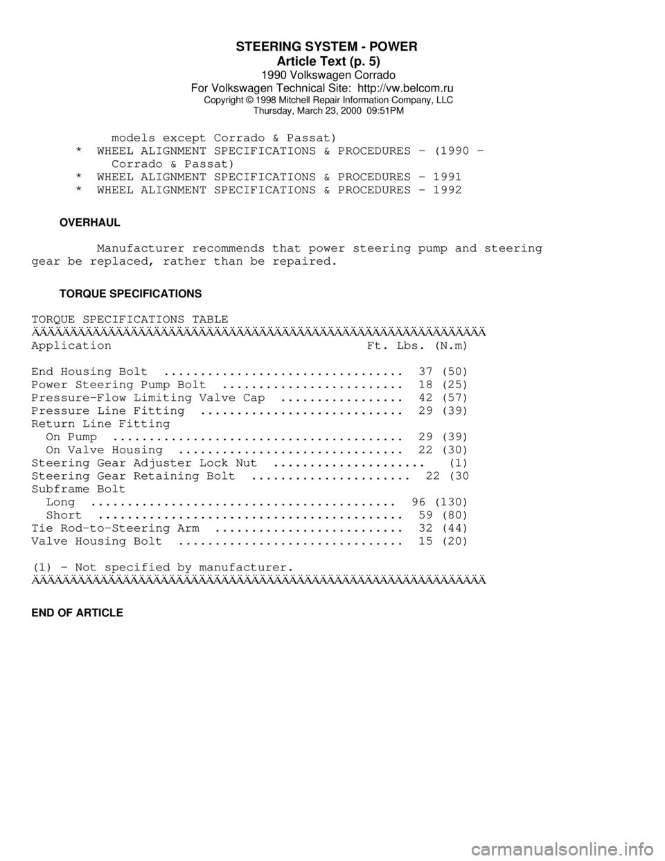
TORQUE SPECIFICATIONS
TORQUE SPECIFICATIONS TABLEÄÄÄÄÄÄÄÄÄÄÄÄÄÄÄÄÄÄÄÄÄÄÄÄÄÄÄÄÄÄÄÄÄÄÄÄÄÄÄÄÄÄÄÄÄÄÄÄÄÄÄÄÄÄÄÄÄÄÄÄApplication Ft. Lbs. (N.m)
End Housing Bolt ................................. 37 (50)
Power Steering Pump Bolt ......................... 18 (25)
Pressure-Flow Limiting Valve Cap ................. 42 (57)
Pressure Line Fitting ............................ 29 (39)
Return Line Fitting
On Pump ........................................ 29 (39)
On Valve Housing ............................... 22 (30)
Steering Gear Adjuster Lock Nut ..................... (1)
Steering Gear Retaining Bolt ...................... 22 (30
Subframe Bolt
Long .......................................... 96 (130)
Short .......................................... 59 (80)
Tie Rod-to-Steering Arm .......................... 32 (44)
Valve Housing Bolt ............................... 15 (20)
(1) - Not specified by manufacturer.
ÄÄÄÄÄÄÄÄÄÄÄÄÄÄÄÄÄÄÄÄÄÄÄÄÄÄÄÄÄÄÄÄÄÄÄÄÄÄÄÄÄÄÄÄÄÄÄÄÄÄÄÄÄÄÄÄÄÄÄÄEND OF ARTICLE
Page 756 of 906
SUSPENSION - FRONT
Article Text (p. 4)
1990 Volkswagen Corrado
For Volkswagen Technical Site: http://vw.belcom.ru
Copyright © 1998 Mitchell Repair Information Company, LLC
Thursday, March 23, 2000 09:51PM
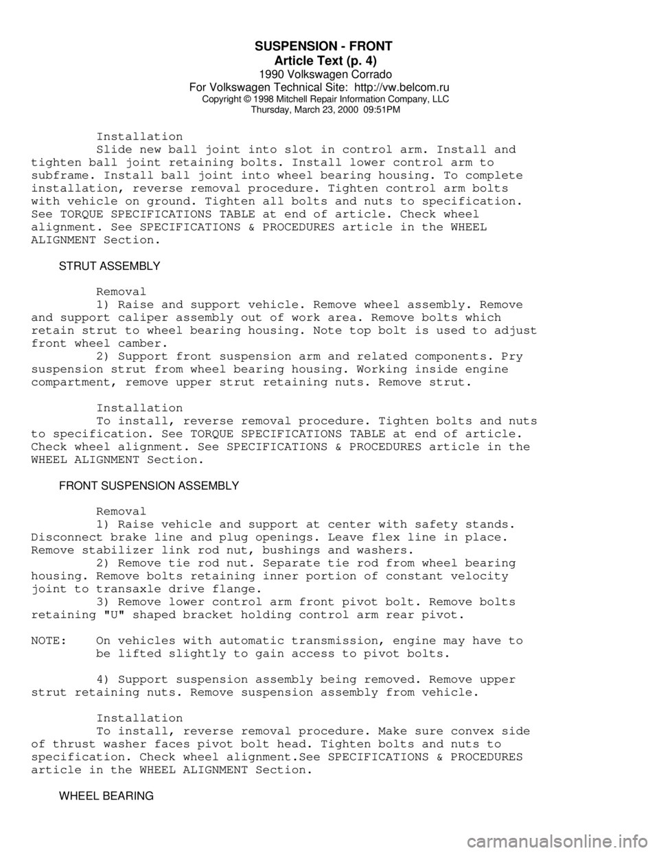
Installation
Slide new ball joint into slot in control arm. Install and
tighten ball joint retaining bolts. Install lower control arm to
subframe. Install ball joint into wheel bearing housing. To complete
installation, reverse removal procedure. Tighten control arm bolts
with vehicle on ground. Tighten all bolts and nuts to specification.
See TORQUE SPECIFICATIONS TABLE at end of article. Check wheel
alignment. See SPECIFICATIONS & PROCEDURES article in the WHEEL
ALIGNMENT Section.
STRUT ASSEMBLY
Removal
1) Raise and support vehicle. Remove wheel assembly. Remove
and support caliper assembly out of work area. Remove bolts which
retain strut to wheel bearing housing. Note top bolt is used to adjust
front wheel camber.
2) Support front suspension arm and related components. Pry
suspension strut from wheel bearing housing. Working inside engine
compartment, remove upper strut retaining nuts. Remove strut.
Installation
To install, reverse removal procedure. Tighten bolts and nuts
to specification. See TORQUE SPECIFICATIONS TABLE at end of article.
Check wheel alignment. See SPECIFICATIONS & PROCEDURES article in the
WHEEL ALIGNMENT Section.
FRONT SUSPENSION ASSEMBLY
Removal
1) Raise vehicle and support at center with safety stands.
Disconnect brake line and plug openings. Leave flex line in place.
Remove stabilizer link rod nut, bushings and washers.
2) Remove tie rod nut. Separate tie rod from wheel bearing
housing. Remove bolts retaining inner portion of constant velocity
joint to transaxle drive flange.
3) Remove lower control arm front pivot bolt. Remove bolts
retaining "U" shaped bracket holding control arm rear pivot.
NOTE: On vehicles with automatic transmission, engine may have to
be lifted slightly to gain access to pivot bolts.
4) Support suspension assembly being removed. Remove upper
strut retaining nuts. Remove suspension assembly from vehicle.
Installation
To install, reverse removal procedure. Make sure convex side
of thrust washer faces pivot bolt head. Tighten bolts and nuts to
specification. Check wheel alignment.See SPECIFICATIONS & PROCEDURES
article in the WHEEL ALIGNMENT Section.
WHEEL BEARING
Page 757 of 906
SUSPENSION - FRONT
Article Text (p. 5)
1990 Volkswagen Corrado
For Volkswagen Technical Site: http://vw.belcom.ru
Copyright © 1998 Mitchell Repair Information Company, LLC
Thursday, March 23, 2000 09:51PM
NOTE: Wheel bearing is destroyed when pressed out of housing. When
either wheel hub or bearing has been removed from housing, a
new bearing must be installed.
Removal
1) Remove axle shaft nut. Raise and support vehicle with
safety stands. Allow suspension to hang free. Remove wheel assembly.
Remove brake caliper attaching bolts. Remove caliper and hang out of
work area. Remove brake disc retaining screw and remove disc.
2) Remove tie rod ball joint from wheel bearing housing.
Remove nut and clamp bolt from control arm ball joint. Remove control
arm ball joint from wheel bearing housing and remove housing.
3) Remove 2 circlips retaining bearing in hub. Using Hub
Remover (VW 295a), press wheel hub from bearing housing. Using a
bearing puller, remove wheel bearing inner race from hub assembly.
Using Bearing Remover (VW 433), press wheel bearing from outboard end
of bearing housing.
Installation
1) Press new bearing race onto hub. Using Bearing & Hub
Installer (VW 472/1), press new bearing into bearing housing from
outboard side. Using same adapter, press wheel hub into bearing
housing. Apply a small bead of locking compound to axle splines before
installing into hub.
2) To complete installation, reverse removal procedure.
Always replace self-locking axle shaft nut. Tighten bolts and nuts to
specification. See TORQUE SPECIFICATIONS TABLE at end of article.
Check wheel alignment. See SPECIFICATIONS & PROCEDURES article in the
WHEEL ALIGNMENT Section.
NOTE: When installing hub, ensure press adapter contacts inner
bearing race only.
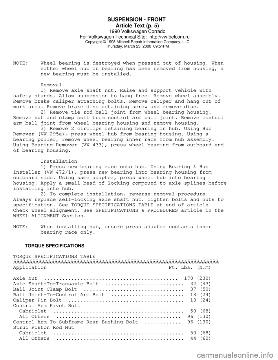
TORQUE SPECIFICATIONS
TORQUE SPECIFICATIONS TABLEÄÄÄÄÄÄÄÄÄÄÄÄÄÄÄÄÄÄÄÄÄÄÄÄÄÄÄÄÄÄÄÄÄÄÄÄÄÄÄÄÄÄÄÄÄÄÄÄÄÄÄÄÄÄÄÄÄÄÄÄÄÄÄÄÄApplication Ft. Lbs. (N.m)
Axle Nut ............................................ 170 (230)
Axle Shaft-To-Transaxle Bolt .......................... 32 (43)
Ball Joint Clamp Bolt ................................. 37 (50)
Ball Joint-To-Control Arm Bolt ........................ 18 (24)
Caliper Pin Bolt ...................................... 18 (24)
Control Arm Pivot Bolt
Cabriolet ........................................... 50 (68)
All Others ......................................... 96 (130)
Control Arm-To-Subframe Rear Bushing Bolt ............ 96 (130)
Strut Piston Rod Nut
Cabriolet ........................................... 50 (68)
All Others .......................................... 44 (60)