1990 MITSUBISHI ECLIPSE brake
[x] Cancel search: brakePage 269 of 391

‘4) Once the operation is step (2) is completed, the
hydraulic control device functions by hydraulic
pressure force to change the state of the
clutches and brakes to accomplish the gear
shifting. To minimize the shock that would
otherwise be produced during gear shifting,
hydraulic pressure is controlled during the gear
shifting period by the “duty control” of the
pressure control solenoid valve. The duty control
is explained later.
‘HYDRAULIC PRESSURE CONTROL DURING
SHFIING(1) The hydraulic pressure that functions during
gear shifting to engage the clutches and apply
the brakes is regulated by the pressure control
valve, The hydraulic pressure that works on the
pressure control valve is further regulated by the
pressure control solenoid valve which functions
under the control of the transaxle control unit.
The transaxle control unit controls the solenoid
valve through the duty control, thus providing
appropriate regulation of the hydraulic pressure.
(2)
(3)
(4)The transaxle control unit decides the timing of
the gear shifting period (during which ‘it per-
forms hydraulic pressure control for gear shift-
ing) according to the change in the kickdown
drum rotating speed that it detects. The unit
identifies the time just before the kickdown
brake is applied and uses that as the timing for
initiating control of the hydraulic pressure which
is to be applied to the kickdown brake.
When the transaxle is cold, the fluid viscosity is
high, causing slower oil pressure response. in
such conditions, the transaxle control unit pro-
vides a correction for the oil pressure by
changing the control duty of the pressure control
solenoid valve.
This control is performed when the fluid temper-
atures as indicated by the oil temperature
sensor is lower than
60°C (140°F).After the engine has been started and the
vehicle is inmotion, the transaxle
continues torefine its performance
est possiblegear shifting.control unit
for smooth-
tHFigure B
- Duty(%)
17500661750067
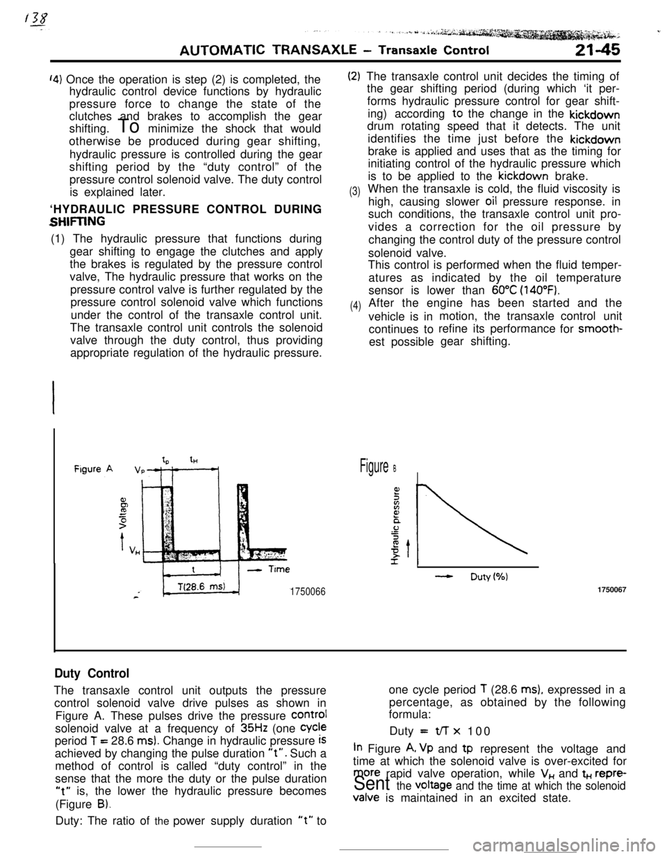
Duty ControlThe transaxle control unit outputs the pressureone cycle period
T (28.6 ms), expressed in a
control solenoid valve drive pulses as shown inpercentage, as obtained by the following
formula:
Figure A. These pulses drive the pressure
COrmIsolenoid valve at a frequency of
35Hz (one Cycleperiod
T = 28.6 ms). Change in hydraulic pressure iSDuty =t/-r x 100
achieved by changing the pulse duration
“t”. Such aIn Figure A, Vp and tp represent the voltage and
method of control is called “duty control” in thetime at which the solenoid valve is over-excited for
sense that the more the duty or the pulse duration
more rapid valve operation, while V,, and t+., repre-
“t” is, the lower the hydraulic pressure becomesSent the v,oltage and the time at which the solenoid(Figure
B).Valve is maintained in an excited state.
Duty: The ratio of the power supply duration
“t” to
Page 270 of 391

---21-46AUTOMATIC TRANSAXLE
- Transaxle Control
Figure A
IICITime (sec.)f
IiFigureB ,
II
cGear Shift Operation
(3rd to 4th)While the vehicle is being drive in
3rd gear, the gear ratio is I :1; that is, the torque converter turbine rotating speed, i.e. the
input shaft rotating speed
(NT), the kickdown drum rotating
speed
(No) and the transfer drive gear rotating speed (No) are
all the same.
Let us explain the
3rd to 4th gear shift at this point, as it is easy
to understand.
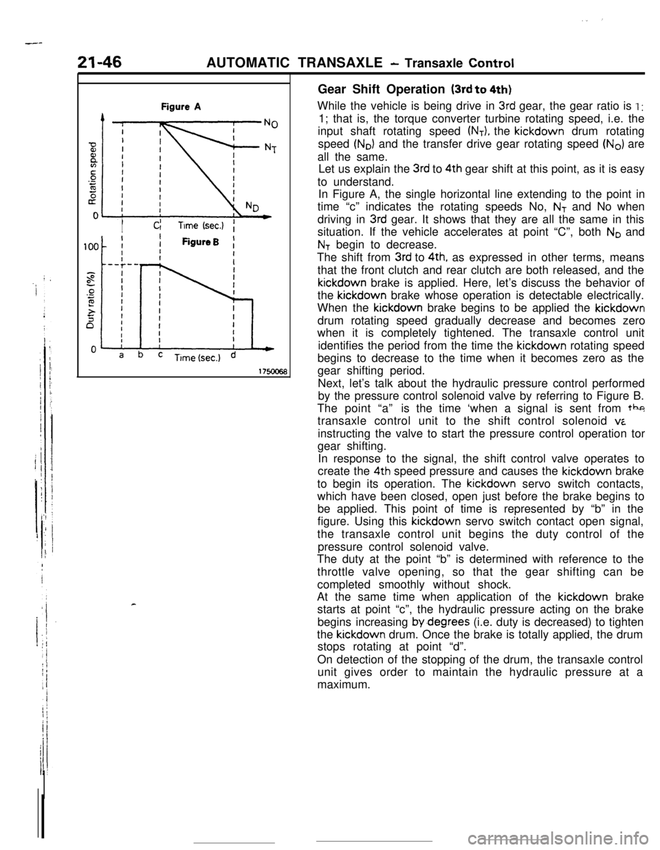
In Figure A, the single horizontal line extending to the point in
time “c” indicates the rotating speeds No,
NT and No when
driving in
3rd gear. It shows that they are all the same in this
situation. If the vehicle accelerates at point “C”, both
No and
NT begin to decrease.
The shift from
3rd to 4th, as expressed in other terms, means
that the front clutch and rear clutch are both released, and thekickdown brake is applied. Here, let’s discuss the behavior of
the kickdown brake whose operation is detectable electrically.
When the kickdown brake begins to be applied the kickdown
drum rotating speed gradually decrease and becomes zero
when it is completely tightened. The transaxle control unit
identifies the period from the time the kickdown rotating speed
begins to decrease to the time when it becomes zero as the
gear shifting period.
Next, let’s talk about the hydraulic pressure control performed
by the pressure control solenoid valve by referring to Figure B.
The point “a”is the time ‘when a signal is sent from tbg
transaxle control unit to the shift control solenoid
viinstructing the valve to start the pressure control operation tor
gear shifting.
In response to the signal, the shift control valve operates to
create the 4th speed pressure and causes the kickdown brake
to begin its operation. The kickdown servo switch contacts,
which have been closed, open just before the brake begins to
be applied. This point of time is represented by “b” in the
figure. Using this kickdown servo switch contact open signal,
the transaxle control unit begins the duty control of the
pressure control solenoid valve.
The duty at the point “b” is determined with reference to the
throttle valve opening, so that the gear shifting can be
completed smoothly without shock.
At the same time when application of the kickdown brake
starts at point “c”, the hydraulic pressure acting on the brake
begins increasing by.degrees (i.e. duty is decreased) to tighten
the kickdown drum. Once the brake is totally applied, the drum
stops rotating at point “d”.
On detection of the stopping of the drum, the transaxle control
unit gives order to maintain the hydraulic pressure at a
maximum.
Page 273 of 391

.-AUTOMATIC TRANSAXLE
- Transaxle Control21-49
Transaxlecontrol unit
Eel
6017!au72
THROmE POSITION SENSOR
The throttle position
SenSOr is installed on the throttle body.
The throttle position sensor Of variable resistor type
senses thethrottle valve
opening.
As the throttle shaft turns, the resistance i.e. output voltage of
throttle position sensor changes. This throttle position sensor
output voltage is input to the transaxle control unit to compute
the throttle opening.
The throttle position sensor output voltage can be adjusted by
turning the throttle position sensor body.
Throttle position sensor output characteristics
5
1
0’ ’10 20 30 40 50 60 70 80 82Totally Throttle valve opening (degrees) Totally
closedopened7FUO75control switchKICKDOWN SERVO SWITCH
The adjust sleeve and the retainer constitute the contacts of
the kickdown servo switch. The switch detects the position of
the kickdown piston just before the kickdown brake is applied,
and sends the signal to the transaxle control unit.
When the kickdown servo is not in operation, the switch
contacts are kept closed.
When the hydraulic pressure is applied to the kickdown servo
and the piston is operated,
the’adjust sleeve separates from
the retainer, turning off the. switch.
Using the kickdown servo switch OFF signal as its standard,
thetransaxle control unit controls the 2nd pressure before, and
during application of the brake by actuating the pressure
control solenoid valve.
OVERDRIVE CONTROL SWITCH
When the overdrive control switch is ON, operation is as a
O-speed automatic transaxle.
When the overdrive control switch is OFF, the indicator light
(within the combination meter) is illuminated, and operation
isas a
3-speed automatic transaxle.
Page 275 of 391

AUTOMATIC TRANSAXLE - Transaxle Control21-51
F”“.-SAFE SYSTEM7,
_ transaxle control unit has a fail-safe function
that provides control to achieve maximum vehicle
safety in the event of an electronic circuit failure or
malfunction, or error caused by the driver. The
control and construction are as described below.
(1) The circuit that supplies hydraulic pressure to
the function elements that don’t couple simul-
taneously is composed of a switching valve
device that cannot supply hydraulic pressure
simultaneouslv so that there IS no ‘internal
locking of the gear train.
(2) Even if there is an attempted shift to
Fi (reverse)while the vehicle is moving forward at a speed
of 7 km/h (4.3 mph) or higher, the hydraulic
pressure to the low-reverse brake is electrically
interrupted
SO that the shift cannot be made. Asa result, there is, unlike previously, no damage
to the transaxle and no engine stall.
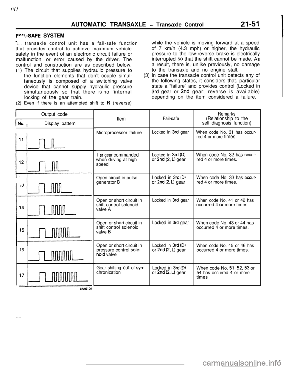
(3) In case the transaxle control unit detects any of
the following states, it considers that. particular
state a “failure” and provides control (Locked in
3rd gear or 2nd gear; reverse is available)
depending on the item considered a failure.
IOutput code
r- INo.Display pattern
16
ItemFail-safeRemarks(Relationship to the
self diagnosis function)Microprocessor failure
Locked in 3rd gear
When code No. 31 has occur-
red 4 or more
times.
1 st gear commandedwhen driving at high
speedLocked in 3rd (D)or 2nd (2, L) gearWhen code No. 32 has occur-red 4 or more times.
Open circuit in pulse
generator
BLocked in 3rd (D)or 2nd (2, L) gearWhen code No. 33 has occur-red 4 or more times.
Open or short circuit in
shift control solenoid
valve A
Locked in 3rd gear
When code No. 41 or 42 hasoccurred 4 or more times.
Open or short circuit in
shift control solenoid
valve
B
Locked in 3rd gearWhen code No. 43 or 44 has
occurred 4 or more times.
Open or short circuit in
pressure control
sole-noid valve
Locked in 3rd (DIor 2nd (2, L) gearWhen code No. 45 or 46 hasoccurred 4 or more times.
Gear shifting out of syn-Locked in 3rd (D)When code No. 51,52,53 or
chronization
or 2nd (2, L) gear54 has occurred 4 or moretimes
12Ao104
-
Page 285 of 391

AUTOMATIC TRANSAXLE - Transaxle Control
.-i:...
21-63To front clutch
Ex ExManual valve
To low/reverse brake
Pressure controlsolenoid valve
1750089
t ‘The hydraulic control system incorporates a “fail1
1safe feature” which prevents the gear shift from
irthe reverse range while driving. This function is
:5activated when the vehicle is running at a speed of 7km/h (4.3 mph) or higher.
;If the selector lever is shifted into the “R” position.
*the transaxle control unit activates the pressure
:control solenoid valve to release the reducing
! ,-pressure. Once the reducing pressure drops, the.-a.rr./ -. jF! ;;1 ;I~N-R control valve is moved toward the right by the
spring force. This closes the No.9 port and causes
the pressure in passage 16 to be released. When
the pressure in passage 16 is released. the check
ball is forced against the right-hand port opening,
thus shutting off the line pressure. As a result, the
low-reverse brake is released. Although the front
clutch is engaged in this situation, the transaxle
cannot transmit the reverse driving power unless
the low-reverse brake is applied. Therefore, when
the transaxle is placed under the abovementioned
condition, it is the same as when it is in neutral.
c
Page 291 of 391

/gi--__ .--.-9
Reducingvalve
To kickdown
servo via 1 - 2
shift valveLine pressureAUTOMATIC TRANSAXLE
- Transaxle Control21-69
PRESSURE CONTROL VALVE, SOLENOID
-_ VALVE AND N-R CONTROL VALVE
: Pressure Control Valve
: This valve regulates the pressure supplied to each
clutch under the control of the pressure control
j.. solenoid<,A ,valve to eliminate shock at the time ofPressure Control Solenoid Valve
This valve has its duty controlled by the transaxlecontrol unit command. It changes an electric com-
mand to corresponding hydraulic pressure.
N-R Control Valve
This valve prevents shock from occurring when the
select lever is shifted from “N” to
“R” (or from “P”
to
“R”) by controlling the oil pressure applied to the
low-reverse brake..Stopping (Selector lever in
“D” or “2”)
‘r) obtain adequate creep force when stopping, the
is kept in
2nd gear by directing the
to the rear clutch and the kickdown brake.
purpose, the pressure acting on the
=nnm is adjusted by the following method
- .--v.._ _ _ __ --Tan that it would be when driving in
..d gear.
he nrennurecontrol solenoid valve is duty control-
..s,. ..Jtransaxle control unit so that the No.231..a
pressure will be lower than the No.23
fine
bressure (reducing pressure). As a result, the
level lower ttlpressure control valve moves to the left under the
line pressure which acts on the difference in area
between the pressure control valve
# 1 and #2lands and the reducing pressure which acts on the
difference in area between the
#2 and #3 lands,
thus closing the No. 5 port by its
#2 land. This
reduces the No. 10 port pressure and the pressure
control valve is moved to the right by the spring
force. Through the No.5 port thus opened, the line
pressure is directed to the kickdown servo. The
pressure applied to the kickdown servo is adjusted
by the above-mentioned sequence.
-
Page 292 of 391

. : j21-70AUTOMATIC TRANSAXLE
- Transaxle Control1st Gear (Selector Lever in “D” or
“2”)
Reducingvalve
D
1
Ex
4Line
’pressureTo low/reverse
brake via 1 - 2shift valveLine pressure
Ext 1
Reducing0 pressure
1 1 ExPressure control 1 b--,N-R control, ,
\ON (Chty 100%)
17soo96On command from the
transaxle control unit, the
duty of the pressure control solenoid valve is set at
100 percent (solenoid is constantly energized). This
reduces the No.23b line pressure to the minimum
level. As
4 result, the pressure control valve is
forced to
ihe left and the No. 5 port is closed, whichprevents pressure from being directed to . the
low-reverse brake via the
l-2 shift valve.
In very low vehicle speeds, however, the duty is set
to zero percent for the maximum pressure, which is
most practical for the control purpose.
Page 293 of 391

AUTOMATIC TRANSAXLE - Transaxle Control21-71
‘ift (Selector Lever in “D” or “2”)
ReducingLine
ipressureTo kickdown servo
or from clutch
via3H
l-r
I
1 - 2 shift valve
Line pressure
Ext 1II ”i1
Reducingpressure
N-R control,,
II& Pressure control
solenoid valve
b-l
To ensure a smooth gear change when upshifting
:from 1st to 2nd, 2nd to 3rd. etc., the transaxle
lcontrol unit controls the duty of the pressure control
z$olenoid valve in order to regulate the control‘pressure established in the
#23b line which gov-
‘ems the operationof the pressure control valve. The
Jlne pressure that flows from the No.5 port to the
No. 10 port is regulated in this way.
-
i& all upshifts are controlied in a similar manner. the
icontrol for the upshift from 1st to 2nd gear will be
explained as an example.
The state of the hydraulic line in the
1st gear
condition is as mentioned on the previous page.
Ifthe transaxle control unit gives order that an upshift
from the
1st to the 2nd gear be initiated and the
duty of the pressure control solenoid valve
is‘usted accordingly, the No.23b line Pressure
is
-.dught higher than it is. in 1st gear. Then. the
pressure control valve moves to the right, opening
the No.5 port. Through the
No.5 port thus opened.
the line pressure from the No. 10 port is directed to
the kickdown servo via the l-2 shift valve. When
the line pressure is applied between the
# 1 and # 2
lands. of the rxessure control valve, the pressureDuty control
+OFF
1750097
effectively acts on an area equivalent to the differ-
ence in area between these two lands, and pushes
the valve to the left; the No. 5 port is closed by the
#2 land.
When the No. 5 port is closed, the No. 10 port
pressure decreases and, as a result, the valve
moves to the right. opening the No.5 port. Through
the No.5 port thus opened, line pressure is intro-
duced. By this sequence, the pressure directed to
the kickdown servo through the No. 10 port is
controlled. The No. 10 pressure is controlled by the
duty of the pressure control solenoid valve. That is.
if the duty is increased, the No.23b line pressure
which pushes the pressure control valve to the right
decreases and this causes a reduced No. 10 port
pressure.When the
1st to 2nd upshift is completed. the
pressure control solenoid valve is deactivated. In
this state, the No.23b line pressure level is equiva-
lent to that of the No.23 line and, therefore, the
pressure control valve is held pushed all the way to
the right. allowing the No.5 port line pressure to be
applied directly to the kickdown servo through the
No. 10 port and thus the kickdown brake is applied.