Page 280 of 391

-
!-I
I!I
21-56AUTOMATIC TRANSAXLE - Transaxle Control~-REGULATOR VALVE
To torque convener
control valve
t
Toshift control valve,
pressure control valve
and N-D control valve(in “D”. ”2” or “L” range)
“D”.“2” or “L” range)
Oil filter
I1
To N-R control valve(in “R” range)Line relief valve
Oil pan
l
1750076
! To torque convener
IL‘I:control valve
Line pressure Pump
Li Ae(from oil pump) suctionprest$$)7,This
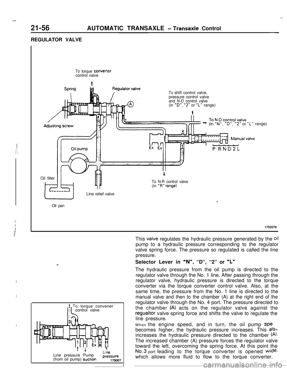
valve regulates the hydraulic pressure generated by the oilpump to a hydraulic pressure corresponding to the regulator
valve spring force. The pressure so regulated is called the line
pressure.Selector Lever in
‘N”, “D”, “2” or “L”The hydraulic pressure from the oil pump is directed to the
regulator valve through the No. 1 line. After passing through the
regulator valve, hydraulic pressure is directed to the torque
converter via the torque converter control valve. Also, at the
same time, the pressure from the No. 1 line is directed to the
manual valve and then to the chamber (A) at the right end of theregulator valve through the No. 4 port. The pressure directed to
the chamber
(A) acts on the regulator valve against theregualtor valve spring force and shifts the valve to regulate the
line pressure.
When the engine speed, and in turn, the oil pump spe
becomes higher, the hydraulic pressure increases. This
aI%increases the hydraulic pressure directed to the chamber
(A).The increased chamber (A) pressure forces the regulator valve
toward the left, overcoming the spring force. At this point theNo.3 port leading to the torque converter is opened
wide+which allows more fluid to flow to the torque converter.
Page 335 of 391

23-18BODY -Body Color Code / Body Color Code Interpretation / Solid
izsiii
Noofl -ENGINE -TNANS I
coLm %F
-T-iI/IBody color code0010163BODY COLOR CODE
The body color code is imprinted on the vehicle information
code plate, which is mounted on the front deck.
BODY COLOR CODE INTERPRETATION
The information contained in the body color code is explained inthe body color parts.
BODY COLOR
Check the vehicle’s body color code, and then use this body color chart to determine the refinishing paint ___
supplier from which the color can be purchased.(M): Metallic paint
(P): Pearl tone paint
B”%d:‘orBody colorColor numberBody color nameEngine compartment and
lug-gage compartment color
Color numberColor name
,814
H18
Rll
R33
w12 _c
BLUE (MI
UGRAY (Mvt)
RED
RED (MI
WHITE
AC10814
AC10818
AC1081 1
AC10833
AC10812Bright Blue
(MI
LT. Mynx
Diamond Star (MI
Flash Red
Raspberry Red (MI
Bright White
BLACKAC10813Black
n R16
T81
T93
D/RED (PIAC10916
D/BLUE (Ml
AC1 0881
TURQUOISE (MIAC 10893
SOLID
i
Common solid,Solid on this vehicleISolid on this vehicle has one more layer of a clear coat on the
Itop coating to increase depth and luster.
IAs for coating operation, this solid is applied by the samf
-”procedure as metallic coat.
I Pre-treatmentElectrodeposition coating
Page 371 of 391
-.-- ----_-
24-8HEATERS AND AIR CONDITIONING - Compressor
COMPRESSORR24GbCOMPRESSOR CONTROL
When both the blower switch and air conditioner
switch are ON, ON-OFF control of the magnetic
clutch is accomplished by the auto compressorcontrol unit. dual pressure switch, engine coolant
temperature switch and
MPI control unit.
Sub fusible
link
Dedicatedfuse
Air conditioner
compressor relayrOFfCompressor
magnetic clutch
q l
Fusible link
lgnitionsyhWqb 1Auto compressor control unit
ITT1 I
0 bIAirAir
inlettherm0
4sensorsensor
Engine coolanttemperature switch
Enginecontrol unit13A0167
Page 372 of 391
19/---..-_HEATERS AND AIR CONDITIONING
- Idle Speed Control24-9
Ii” E SPEED CONTROL
1.increasing idle speed to withstand air condition-
er load
When the compressor is placed in the ON state
with the engine at idle, the idling speed of the
engine will be increased by approx. 150 rpm to
prevent generation of vibration and also to
prevent the engine from stalling.-
2.The stepper motor types of actuators is used for
increasing the idle speed.
IDLE SOPEED CONTROL CIRCUITFusible link
Dedicatedfuse
Air
condi-tioner
compressor relay
I-gcfc
Lll
Compre:Ignition
switch
Sub fusible
linkswitch
Auto compressor
As
mlef kr Ihemo
Ax;,: engine control unit
Idle speed control
Y *e:Q
1
$4.1111.Pk+F)rmagneticIJ
clutchEngine controlunit13AO167
Page 374 of 391

25-2EMISSION CONTROL SYSTEMS - General Information
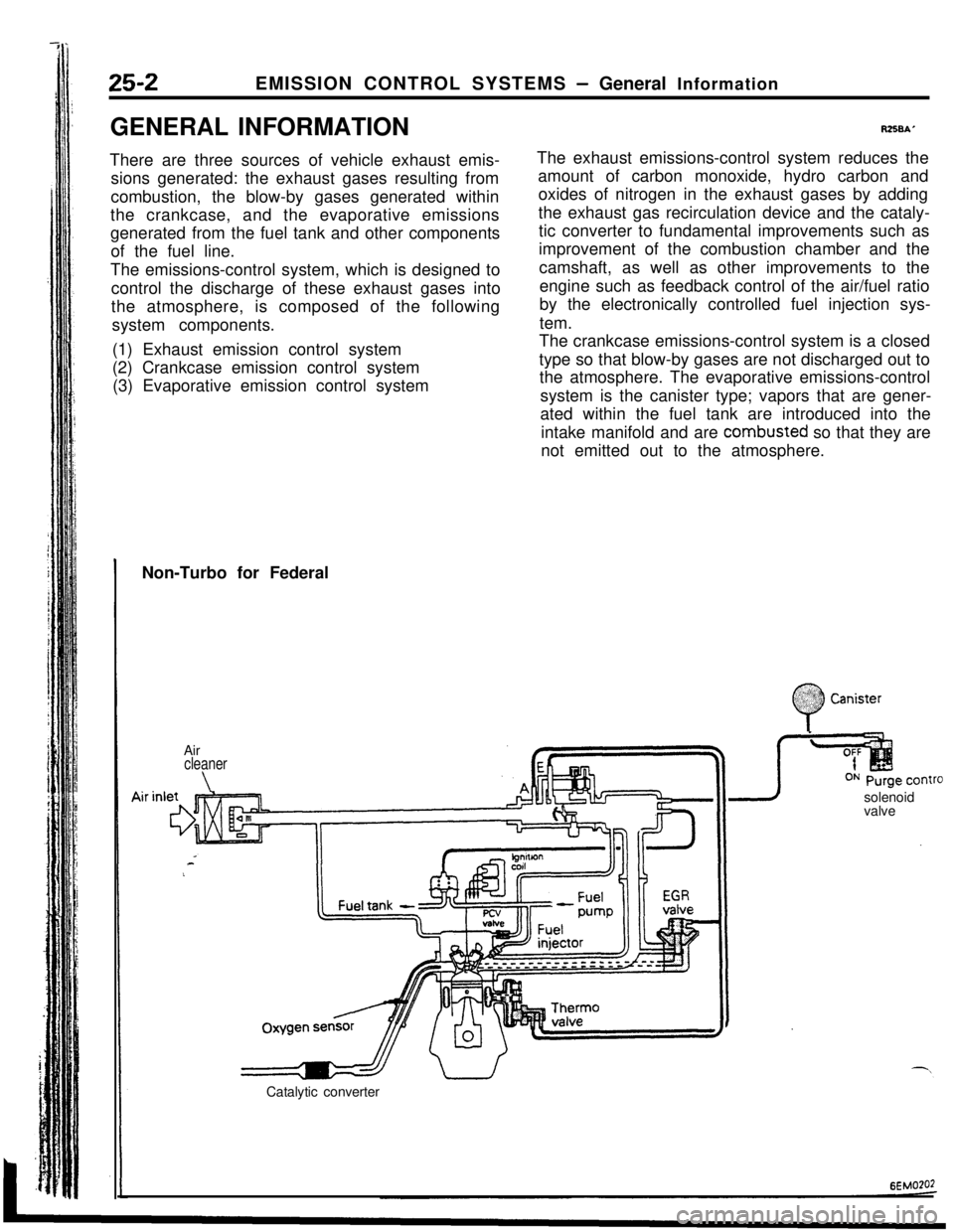
GENERAL INFORMATION
There are three sources of vehicle exhaust emis-
sions generated: the exhaust gases resulting from
combustion, the blow-by gases generated within
the crankcase, and the evaporative emissions
generated from the fuel tank and other components
of the fuel line.
The emissions-control system, which is designed to
control the discharge of these exhaust gases into
the atmosphere, is composed of the following
system components.
(1) Exhaust emission control system
(2) Crankcase emission control system
(3) Evaporative emission control system
R258A’The exhaust emissions-control system reduces the
amount of carbon monoxide, hydro carbon and
oxides of nitrogen in the exhaust gases by adding
the exhaust gas recirculation device and the cataly-
tic converter to fundamental improvements such as
improvement of the combustion chamber and the
camshaft, as well as other improvements to the
engine such as feedback control of the air/fuel ratio
by the electronically controlled fuel injection sys-
tem.
The crankcase emissions-control system is a closed
type so that blow-by gases are not discharged out to
the atmosphere. The evaporative emissions-control
system is the canister type; vapors that are gener-
ated within the fuel tank are introduced into the
intake manifold and are combusted so that they are
not emitted out to the atmosphere.
Non-Turbo for Federal
Air
cleaner
\solenoid
valve
Catalytic converter
:
0
$2:) Canister:.:
Page 376 of 391

--.
25-2EMISSION CONTROL SYSTEMS - General Information
GENERAL INFORMATION
There are three sources of vehicle exhaust emis-
sions generated: the exhaust gases resulting from
combustion, the blow-by gases generated within
the crankcase, and the evaporative emissions
generated from the fuel tank and other components
of the fuel line.
The emissions-control system, which is designed to
control the discharge of these exhaust gases into
the atmosphere,is composed of the following
system components.
(1) Exhaust emission control system
(2) Crankcase emission control system
(3) Evaporative emission control system
RZSBAThe exhaust emissions-control system reduces the
amount of carbon monoxide, hydro carbon and
oxides of nitrogen in the exhaust gases by adding
the exhaust gas recirculation device and the cataly-
tic converter to fundamental improvements such as
improvement of the combustion chamber and the
camshaft, as well as other improvements to the
engine such as feedback control of the air/fuel ratio
by the electronically controlled fuel injection sys-
tem.
The crankcase emissions-control system is a closed
type so that blow-by gases are not discharged out to
the atmosphere. The evaporative emissions-control
system is the canister type; vapors that are gener-
ated within the fuel tank are introduced into the
intake manifold and are combusted so that they are
not emitted out to the atmosphere.
Non-Turbo for Federal
.;. :
0
.%??? CanisterAir
cleaner
\valveOxygenFuel tank
-a I”’ ,T
sensr’
Catalytic converter
6EMO?O2
Page 379 of 391
‘Sv’_ -EMISSION CONTROL SYSTEMS
-Exhaust Gas Recirculation (EGR) System25-5
FYHAUST GAS RECIRCULATION
\ ,GR) SYSTEM
RZSCAAB
EGR system is designed to reduce oxides of
nitrogen in exhaust emissions. In this system, the
exhaust gas is partially recirculated from the
ex-haust manifold into the intake manifold while EGR
flow is controlled by the
EGR control valve.
OPERATION
The amount of
EGR flow is reaulated bv the throttlevacuum is low during engine idling, or during
wide-open throttle operation, the EGR control valve
is closed by the force.of the spring, with the result
that there is no flow of EGR gas.
If the temperature of the engine coolant is below
65°C (149”F), the therm0 valve opens and the “E”
port vacuum is leaked to the throttle body “A” port,
with the result that the
EGR valve does not function.
l ’E”Portvacuum. &cause the “E” port
Therm0 valve
NOTE-This figure shows Non-Turbo.6EM0136
Page 380 of 391

-.-
25-6EMISSION CONTROL SYSTEMS- Exhaust Gas Recirculation (EGR) System
OPERATION
The engine control unit functions to calculate the
engine load, based upon the intake air volume
signals (from the air-flow sensor) and the rpm
signals (from the crank-angle sensor), and the
EGRcontrol solenoid valve is activated according to the
engine load. The
EGR amount is then regulated
according to the engine load calculated in this way.maintaining driveability during cold.
When, as a result of clogging of the
EGR cant’valve or as a result of an operational
malfunctio,.,the
EGR flow volume decreases, the EGR gas
temperature downstream. from the
EGR control
valve decreases. The engine control unit functions
to detect the
operation conditions of the EGRLoad
a Intake air volume/Engine rpmsystem by this characteristic.
If, however, the engine coolant temperature is low,
the actuation duty is attenuated, the
EGR control
valve activation negative pressure (vacuum) is
leaked from the throttle body A port, thus reducing
or interrupting the
EGR flow volume and therebyThe temperature of the
EGR gas is detected by the
EGR gas temperature sensor which is equipped at
the
EGR control valve; when the temperature
decreases to a low level, the engine warning light
(malfunction indicator light) illuminates in order to
advise the driver that a malfunction has occurred in
the
EGR system.
EGR
contcEGR control
solenoid valve
/Control
relay
1Engine control unit
Enginewarning
light