Page 539 of 1164

TRANSAXLE Jl
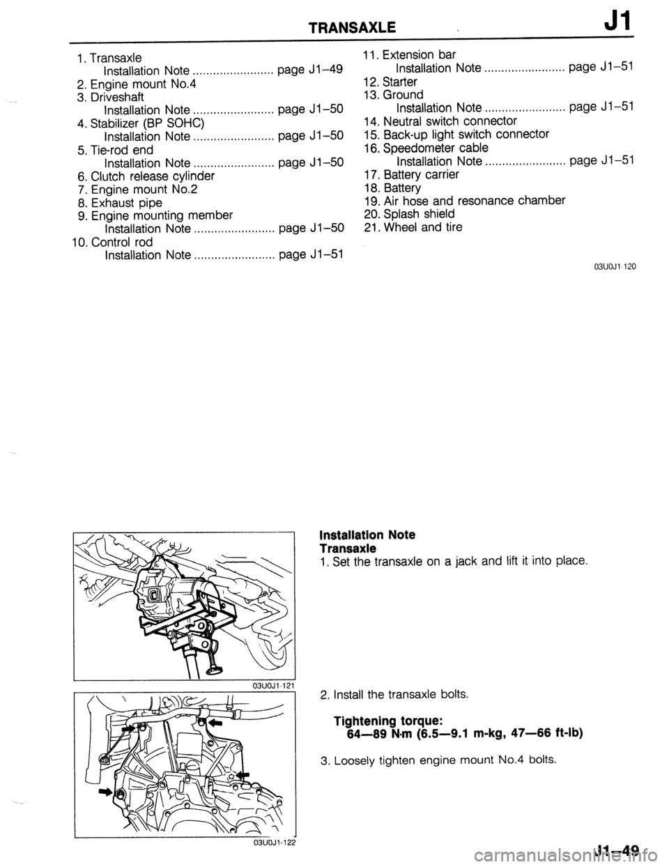
1. Transaxle
Installation Note ..,......,.............. page Jl-49
2. Engine mount No.4
3. Driveshaft
Installation Note . . . . . . . . . . . . . . . . . . . . . . . . page Jl-50
4. Stabilizer (BP SOHC)
Installation Note . . . . . . . . . . . . . . . . . . . . . . . . page Jl-50
5. Tie-rod end
Installation Note ,........,..,........... page Jl-50
6. Clutch release cylinder
7. Engine mount No.2
8. Exhaust pipe
9. Engine mounting member
Installation Note . . . . . . . . . . . . . . . . . . . . . . . .
page Jl-50
10. Control rod
Installation Note . . . . . . . . . . . . . . . . . . . . . . . . page Jl-51 11. Extension bar
Installation Note . . . . . . . . . . . . . . . . . . . . . . . . page Jl-51
1 12. Starter
13. Ground
Installation Note .,..,...,......,........ page Jl-5
14. Neutral switch connector
15. Back-up light switch connector
16. Speedometer cable
Installation Note . . . . . . . . . . . . . . . . . . . . . . . .
page Jl-5
17. Battery carrier
18. Battery
19. Air hose and resonance chamber
20. Splash shield
21. Wheel and tire 1
Installation Note
Transaxle
1. Set the transaxle on a jack and lift it into place.
Install tne transaxle oorts.
Tightening torque:
64-69 N*rn (6.5-9.1 m-kg, 47-66 ft-lb)
Loosely tighten engine mount No.4 bolts.
Jl-49
Page 690 of 1164

CONVENTIONAL BRAKE SYSTEM
Installation note
Manual adjustment gear
1. Turn the manual adjustment gear clockwise until the brake
pads just touch the disc pIaTe.
2. Return the manual adjustment gear l/3-turn
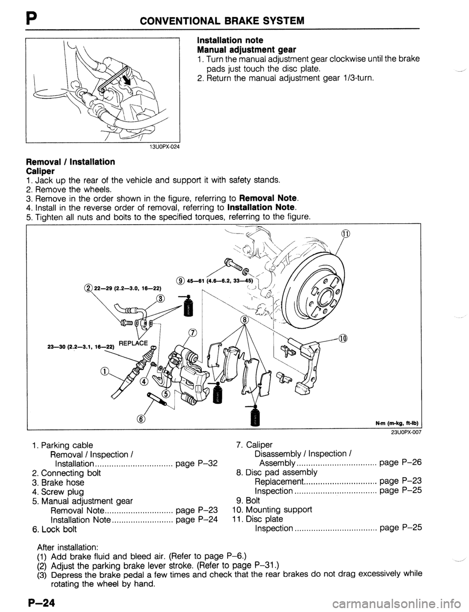
Removal / Installation
Caliper
1. Jack up the rear of the vehicle and support it with safety stands.
2. Remove the wheels.
3. Remove in the order shown in the figure, referring to
Removal Note.
4. Install in the reverse order of removal, referring to Installation Note.
5. Tighten all nuts and bolts to the specified torques, referring to the figure.
@ 22-29 (2.2-3.0, 16-22)
23-30 (2.2-3.1, 16-
N.m (m-kg, R-lb)
23UOPX-00
1. Parking cable 7. Caliper
Removal I Inspection / Disassembly / Inspection /
Installation . . . . . . . . . . . . . . . . . . . . . . ,.,........ page P-32 Assembly ,.....*........................... page P-26
2. Connecting bolt 8. Disc pad assembly
3. Brake hose Replacement ,...,.,.,.,........*........... page P-23
4. Screw plug Inspection . . . . . . . ..*......................... page P-25
5. Manual adjustment gear 9. Bolt
Removal Note . . . . . . . . . . . . . . . ,,..,.,....... page P-23 10. Mounting support
Installation Note ,....,.,..,.,...,., ,...,., page P-24 11, Disc plate
6. Lock bolt Inspection .,...........*..................... page P-25
After installation:
(1) Add brake fluid and bleed air. (Refer to page P-6.)
(2) Adjust the parking brake lever stroke. (Refer to page P-31 .)
(3) Depress the brake pedal a few times and check that the rear brakes do not drag excessively while
rotating the wheel by hand.
P-24
Page 717 of 1164
R
FRONTSHOCKABSORBERANDSPRING
Removal / Installation
1. Jack up the front of the vehicle and support it with safety stands.
2. Remove the wheels.
3. Remove in the order shown in the figure.
4. Install in the reverse order of removal, referring to Installation Note.
5. After installation, measure the front wheel alignment, and adjust it if necessary.
Caution
l Retighten the shock absorber lower bolts to the specified torque after lowering the vehicle
(unladen condition).
1. Clip
2. Nut
3. Bolt
4. Nut 5. Shock absorber and spring
N.m (m-kg, R-lb
23UORX-0‘
- .^
Disassembly ............................... page H-l Z
Inspection ................................... page R-l 3
Assembly.. .................................. page R-14
Installation Note.. ........................ page R-12
R-l 1
Page 722 of 1164

FRONT SUSPENSION (STRUT)
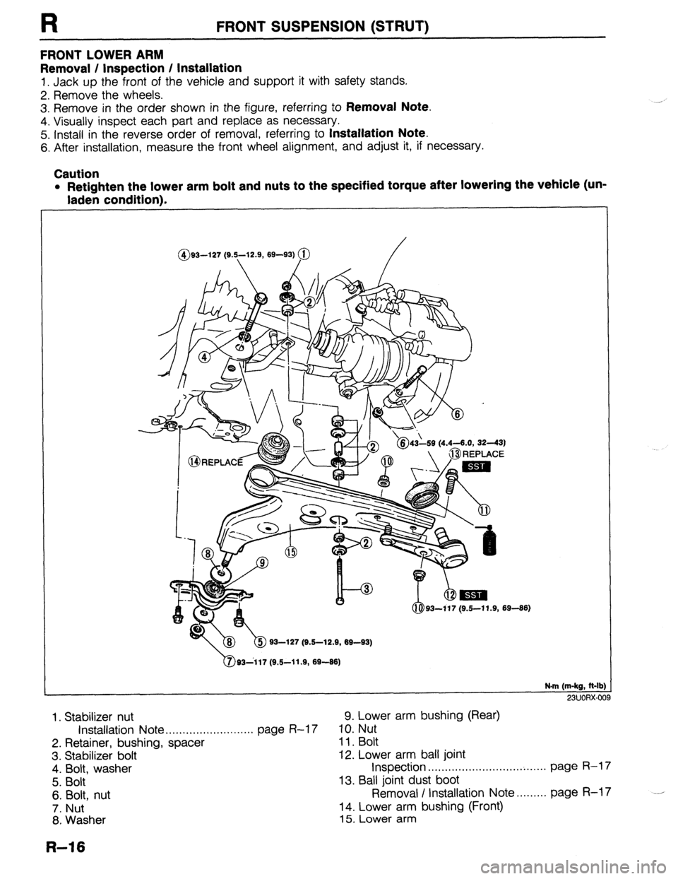
FRONT LOWER ARM
Removal / Inspection / Installation
1. Jack up the front of the vehicle and support it with safety stands.
2. Remove the wheels.
3. Remove in the order shown in the figure, referring to
Removal Note.
4. Visually inspect each part and replace as necessary.
5. Install in the reverse order of removal, referring to
Installation Note.
6. After installation, measure the front wheel alignment, and adjust it, if necessary.
Caution
l Retighten the lower arm bolt and nuts to the specified torque after lowering the vehicle (un-
laden condition).
@G-l27 (SE,-12.9, M-93) @
I ‘&43h (4.4-6.0, 32-43)
b 93-127 (9.6-12.9, W-93)
N-m (m-kg, It-lb:
23UORX-O(
1. Stabilizer nut 9. Lower arm bushing (Rear)
Installation Note . . . . . . . . . . ..I............. page R-17 10. Nut
2. Retainer, bushing, spacer 11. Bolt
3. Stabilizer bolt 12. Lower arm ball joint
4. Bolt, washer Inspection . . . . . . . . . . . . . . . . . . ..*..*..........* page R-17
5. Bolt 13. Ball joint dust boot
6. Bolt, nut Removal I Installation Note......... page R-17 .--
7. Nut 14. Lower arm bushing (Front)
8. Washer 15. Lower arm
R-16
Page 724 of 1164
R FRONT SUSPENSION (STRUT)
FRONT STABILIZER
Removal / Inspection / Installation
1. Jack up the front of the vehicle and support it with safety stands.
2. Remove the wheels.
3. Remove the undercover.
4. Remove in the order shown in the figure, referring to
Removal Note.
5. Visually inspect each part and replace as necessary.
6. Install in the reverse order of removal, referring to
Installation Note.
Caution
l Retighten the stabilizer bracket bolts to the specified torque after lowering the vehicle (un-
laden condition).
@ 37-52 (3.8-5.3, 27-38)
N.m (m-kg, R-lb:
23UORX-0’
1. Stabilizer nut 5. Stabilizer bracket
Installation Note . . . . . . . . . . . . . . . . . ..*...... page R-19 6. Stabilizer bushing
2. Retainer, washer,
spacer
3. Stabilizer bolt
4. Bolt installation Note .,.....,..,...,........... page 11-19
7. Stabilizer bar
Removal / installation Note . . . . . . . . . page R-l 9
R-l 8
Page 727 of 1164
REAR SUSPENSION (STRUT)
REAR SHOCK ABSORBER AND SPRING
Removal / Installation
R
1. Jack up the rear of the vehicle and support it with safety stands.
2. Remove the wheels.
3. Remove in the order shown in the figure.
4. Install in the reverse order of removal.
5. After installation, measure the rear wheel alignment, if necessary.
Caution
l Retighten the shock absorber lower bolts to the specified torque after lowering the vehicle
(unladen condition).
.
/
2940 (3.0-4.1, 22-30)
‘I I L 93-127 (9.5-12.9, 69-93)
/
N-m (m-kg, R-lb)
23UORX-01’
1. Clip
5. Shock absorber and spring
2. Nut Disassembly . . . . . . . . . . . . . . . . . . . . . . . . . . . . . . . page R-22
3. Bolt Inspection ..__._.._ page R-23
4.
Nut Assembly.. . , . , . , , . , . . . . . . . . . . . . . . . . . . . . . . . . . page R-24
R-21
Page 732 of 1164
R REAR SUSPENSION (STRUT)
LATERAL LINK AND TRAILING LINK
Removal / Inspection / Installation
1. Jack up the rear of the vehicle and support it with safety stands.
2. Remove the wheels.
3. Remove in the order shown in the figure.
4. Visually inspect each part and replace as necessary.
5. Install in the reverse order of removal, referring to
Installation Note.
6. After installation, measure the rear wheel alignment, and adjust it if necessary.
Caution
0 Retighten the lateral link and trailing link mounting bolts and nuts to the specified torque af-
ter lowering the vehicle (unladen condition). -
63-93 (6.4
65-l 17 (6.7-l
93-127 (9.5-12.9, 69-93)
N-m (m-kg, R-lb
-^. .^-.. ^
1. Stabilizer nut 4. Cap
Installation Note 5. Nut
. . . . . . . . . . . . . . . . ...‘... page R-27 6. Washer
2. Retainer, bushing, spacer 7. Bolt
3. Stabilizer bolt 8. Retainer 9. Lateral link (front)
10. Lateral link (rear)
11. Bolt, washer
12. Trailing link
x?AJuux-u
R-26
Page 733 of 1164

REAR SUSPENSION (STRUT) R
Installation note
Stabilizer nut
Tighten the stabilizer nuts so that the specified thread is ex,
posed at the end of the bolt.
Specification: 16.2-18.2mm (0.84-0.72 in)
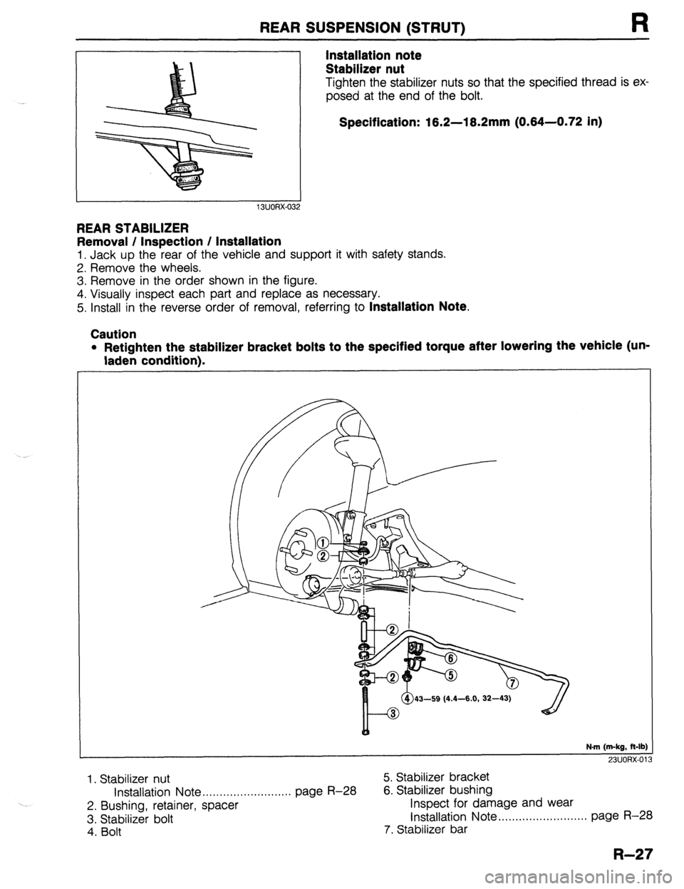
REAR STABILIZER
Removal / Inspection / Installation
1. Jack up the rear of the vehicle and support it with safety stands.
2. Remove the wheels.
3. Remove in the order shown in the figure.
4. Visually inspect each part and replace as necessary.
5. Install in the reverse order of removal, referring to
Installation Note.
Caution
l Retighten the stabilizer bracket bolts to the specified torque after lowering the vehicle (un-
laden condition).
43-59 (4.4-6.0, 32-4
N-m (m-kg, ft-lb)
731KmX.01
---_
1. Stabilizer nut 5. Stabilizer bracket
Installation Note . . . . . . . . . . . . . . . . . . . . . . . . . . page R-28 6. Stabilizer bushing
2. Bushing, retainer, spacer Inspect for damage and wear
3. Stabilizer bolt Installation Note .,,,,,.................... page R-28
4. Bolt 7. Stabilizer bar
R-27