1989 FORD FIESTA warning light
[x] Cancel search: warning lightPage 206 of 296
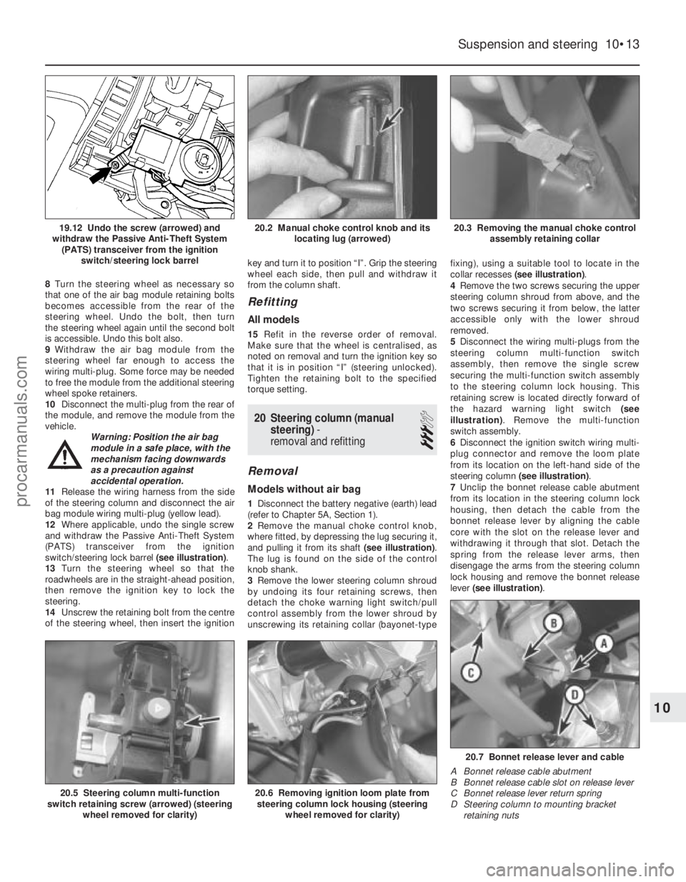
8Turn the steering wheel as necessary so
that one of the air bag module retaining bolts
becomes accessible from the rear of the
steering wheel. Undo the bolt, then turn
the steering wheel again until the second bolt
is accessible. Undo this bolt also.
9 Withdraw the air bag module from the
steering wheel far enough to access the
wiring multi-plug. Some force may be needed
to free the module from the additional steering
wheel spoke retainers.
10 Disconnect the multi-plug from the rear of
the module, and remove the module from the
vehicle. Warning: Position the air bag
module in a safe place, with the
mechanism facing downwards
as a precaution against
accidental operation.
11 Release the wiring harness from the side
of the steering column and disconnect the air
bag module wiring multi-plug (yellow lead).
12 Where applicable, undo the single screw
and withdraw the Passive Anti-Theft System
(PATS) transceiver from the ignition
switch/steering lock barrel (see illustration).
13 Turn the steering wheel so that the
roadwheels are in the straight-ahead position,
then remove the ignition key to lock the
steering.
14 Unscrew the retaining bolt from the centre
of the steering wheel, then insert the ignition key and turn it to position “I”. Grip the steering
wheel each side, then pull and withdraw it
from the column shaft.
Refitting
All models
15
Refit in the reverse order of removal.
Make sure that the wheel is centralised, as
noted on removal and turn the ignition key so
that it is in position “I” (steering unlocked).
Tighten the retaining bolt to the specified
torque setting.
20 Steering column (manual steering) -
removal and refitting
3
Removal
Models without air bag
1 Disconnect the battery negative (earth) lead
(refer to Chapter 5A, Section 1).
2 Remove the manual choke control knob,
where fitted, by depressing the lug securing it,
and pulling it from its shaft (see illustration).
The lug is found on the side of the control
knob shank.
3 Remove the lower steering column shroud
by undoing its four retaining screws, then
detach the choke warning light switch/pull
control assembly from the lower shroud by
unscrewing its retaining collar (bayonet-type fixing), using a suitable tool to locate in the
collar recesses
(see illustration) .
4 Remove the two screws securing the upper
steering column shroud from above, and the
two screws securing it from below, the latter
accessible only with the lower shroud
removed.
5 Disconnect the wiring multi-plugs from the
steering column multi-function switch
assembly, then remove the single screw
securing the multi-function switch assembly
to the steering column lock housing. This
retaining screw is located directly forward of
the hazard warning light switch (see
illustration) . Remove the multi-function
switch assembly.
6 Disconnect the ignition switch wiring multi-
plug connector and remove the loom plate
from its location on the left-hand side of the
steering column (see illustration) .
7 Unclip the bonnet release cable abutment
from its location in the steering column lock
housing, then detach the cable from the
bonnet release lever by aligning the cable
core with the slot on the release lever and
withdrawing it through that slot. Detach the
spring from the release lever arms, then
disengage the arms from the steering column
lock housing and remove the bonnet release
lever (see illustration) .
Suspension and steering 10•13
20.3 Removing the manual choke control
assembly retaining collar20.2 Manual choke control knob and its locating lug (arrowed)19.12 Undo the screw (arrowed) and
withdraw the Passive Anti-Theft System (PATS) transceiver from the ignition switch/steering lock barrel
20.7 Bonnet release lever and cable
A Bonnet release cable abutment
B Bonnet release cable slot on release lever
C Bonnet release lever return spring
D Steering column to mounting bracket retaining nuts
20.6 Removing ignition loom plate fromsteering column lock housing (steering
wheel removed for clarity)20.5 Steering column multi-function
switch retaining screw (arrowed) (steering
wheel removed for clarity)
10
1595Ford Fiesta Remakeprocarmanuals.com
http://vnx.su
Page 213 of 296
1 General information
The bodyshell and underframe on all
models is of all-steel welded construction,
incorporating progressive crumple zones at
the front and rear, and a rigid centre safety
cell. The body styles available include three-
door, five-door, Van and Courier
configurations. A multi-stage anti-corrosion process is
applied to all new vehicles. This includes zinc
phosphating on some panels, the injection of
wax into boxed sections, and a wax and PVC
coating applied to the underbody for its
protection. Inertia reel seat belts are fitted to all
models, and from the 1994 model year
onwards, the front seat belt stalks are
mounted on automatic mechanical tensioners
(also known as “grabbers”). In the event of a
serious front impact, a spring mass sensor
releases a coil spring which pulls the stalk
buckle downwards and tensions the seat belt.
It is not possible to reset the tensioner once
fired, and it must therefore be renewed. Central locking is a standard or optional
fitment on all models. Where double-locking is
also fitted, the lock mechanism is
disconnected (when the system is in use) from
the interior door handles, making it impossible
to open any of the doors or the tailgate from
inside the vehicle. This means that, even if a
thief should break a side window, it will not be
possible to open the door using the interior
handle.
2 Maintenance -
bodywork and underframe
1
The general condition of a vehicle’s
bodywork is the one thing that significantly
affects its value. Maintenance is easy, but
needs to be regular. Neglect, particularly after
minor damage, can lead quickly to further
deterioration and costly repair bills. It is
important also to keep watch on those parts
of the vehicle not immediately visible, for
instance the underside, inside all the wheel
arches, and the lower part of the engine
compartment. The basic maintenance routine for the
bodywork is washing - preferably with a lot of
water, from a hose. This will remove all the
loose solids which may have stuck to the
vehicle. It is important to flush these off in
such a way as to prevent grit from scratching
the finish. The wheel arches and underframe
need washing in the same way, to remove any
accumulated mud, which will retain moisture
and tend to encourage rust. Oddly enough,
the best time to clean the underframe and
wheel arches is in wet weather, when the mud
is thoroughly wet and soft. In very wet weather, the underframe is usually cleaned of
large accumulations automatically, and this is
a good time for inspection.
Periodically, except on vehicles with a wax-
based underbody protective coating, it is a
good idea to have the whole of the
underframe of the vehicle steam-cleaned,
engine compartment included, so that a
thorough inspection can be carried out to see
what minor repairs and renovations are
necessary. Steam-cleaning is available at
many garages, and is necessary for the
removal of the accumulation of oily grime,
which sometimes is allowed to become thick
in certain areas. If steam-cleaning facilities are
not available, there are some excellent grease
solvents available which can be brush-
applied; the dirt can then be simply hosed off.
Note that these methods should not be used
on vehicles with wax-based underbody
protective coating, or the coating will be
removed. Such vehicles should be inspected
annually, preferably just prior to Winter, when
the underbody should be washed down, and
any damage to the wax coating repaired.
Ideally, a completely fresh coat should be
applied. It would also be worth considering
the use of such wax-based protection for
injection into door panels, sills, box sections,
etc, as an additional safeguard against rust
damage, where such protection is not
provided by the vehicle manufacturer. After washing paintwork, wipe off with a
chamois leather to give an unspotted clear
finish. A coat of clear protective wax polish
will give added protection against chemical
pollutants in the air. If the paintwork sheen
has dulled or oxidised, use a cleaner/polisher
combination to restore the brilliance of the
shine. This requires a little effort, but such
dulling is usually caused because regular
washing has been neglected. Care needs to
be taken with metallic paintwork, as special
non-abrasive cleaner/polisher is required to
avoid damage to the finish. Always check that
the door and ventilator opening drain holes
and pipes are completely clear, so that water
can be drained out .Brightwork should be
treated in the same way as paintwork.
Windscreens and windows can be kept clear
of the smeary film which often appears, by the
use of proprietary glass cleaner. Never use
any form of wax or other body or chromium
polish on glass.
3 Maintenance -
upholstery and carpets
1
Mats and carpets should be brushed or
vacuum-cleaned regularly, to keep them free
of grit. If they are badly stained, remove them
from the vehicle for scrubbing or sponging,
and make quite sure they are dry before
refitting. Seats and interior trim panels can be
kept clean by wiping with a damp cloth. If they
do become stained (which can be more apparent on light-coloured upholstery), use a
little liquid detergent and a soft nail brush to
scour the grime out of the grain of the
material. Do not forget to keep the headlining
clean in the same way as the upholstery.
When using liquid cleaners inside the vehicle,
do not over-wet the surfaces being cleaned.
Excessive damp could get into the seams and
padded interior, causing stains, offensive
odours or even rot.
Note
:
If the inside of the vehicle gets wet
accidentally, it is worthwhile taking some
trouble to dry it out properly, particularly
where carpets are involved .
Warning: Do not leave oil or
electric heaters inside the
vehicle for this purpose.
4 Minor body damage-
repair
3
Repairs of minor scratches in
bodywork
If the scratch is very superficial, and does
not penetrate to the metal of the bodywork,
repair is very simple. Lightly rub the area of
the scratch with a paintwork renovator, or a
very fine cutting paste, to remove loose paint
from the scratch, and to clear the surrounding
bodywork of wax polish. Rinse the area with
clean water. Apply touch-up paint to the scratch using a
fine paint brush; continue to apply fine layers
of paint until the surface of the paint in the
scratch is level with the surrounding
paintwork. Allow the new paint at least two
weeks to harden, then blend it into the
surrounding paintwork by rubbing the scratch
area with a paintwork renovator or a very fine
cutting paste. Finally, apply wax polish. Where the scratch has penetrated right
through to the metal of the bodywork, causing
the metal to rust, a different repair technique
is required. Remove any loose rust from the
bottom of the scratch with a penknife, then
apply rust-inhibiting paint to prevent the
formation of rust in the future. Using a rubber
or nylon applicator, fill the scratch with
bodystopper paste. If required, this paste can
be mixed with cellulose thinners to provide a
very thin paste which is ideal for filling narrow
scratches. Before the stopper-paste in the
scratch hardens, wrap a piece of smooth
cotton rag around the top of a finger. Dip the
finger in cellulose thinners, and quickly sweep
it across the surface of the stopper-paste in
the scratch; this will ensure that the surface
of the stopper-paste is slightly hollowed. The
scratch can now be painted over as described
earlier in this Section.
Repairs of dents in bodywork
When deep denting of the vehicle’s
bodywork has taken place, the first task is to
pull the dent out, until the affected bodywork
11•2 Bodywork and fittings
1595Ford Fiesta Remakeprocarmanuals.com
http://vnx.su
Page 215 of 296
7.3a Removing the bonnet release latch
15 minutes after spraying on the final coat of
paint.Allow the new paint at least two weeks to
harden, then, using a paintwork renovator, or
a very fine cutting paste, blend the edges of
the paint into the existing paintwork. Finally,
apply wax polish.
Plastic components
With the use of more and more plastic body
components by the vehicle manufacturers (eg
bumpers. spoilers, and in some cases major
body panels), rectification of more serious
damage to such items has become a matter
of either entrusting repair work to a specialist
in this field, or renewing complete
components. Repair of such damage by the
DIY owner is not really feasible, owing to the
cost of the equipment and materials required
for effecting such repairs. The basic technique
involves making a groove along the line of the
crack in the plastic, using a rotary burr in a
power drill. The damaged part is then welded
back together, using a hot-air gun to heat up
and fuse a plastic filler rod into the groove.
Any excess plastic is then removed, and the
area rubbed down to a smooth finish. It is
important that a filler rod of the correct plastic
is used, as body components can be made of
a variety of different types (eg polycarbonate,
ABS, polypropylene). Damage of a less serious nature (abrasions,
minor cracks etc) can be repaired by the DIY
owner using a two-part epoxy filler repair
material. Once mixed in equal proportions,
this is used in similar fashion to the bodywork
filler used on metal panels. The filler is usually
cured in twenty to thirty minutes, ready for
sanding and painting. If the owner is renewing a complete
component himself, or if he has repaired it
with epoxy filler, he will be left with the
problem of finding a suitable paint for finishing
which is compatible with the type of plastic
used. At one time, the use of a universal paint
was not possible, owing to the complex range
of plastics encountered in body component
applications. Standard paints, generally
speaking, will not bond to plastic or rubber
satisfactorily. However, it is now possible to
obtain a plastic body parts finishing kit which
consists of a pre-primer treatment, a primer and coloured top coat. Full instructions are
normally supplied with a kit, but basically, the
method of use is to first apply the pre-primer
to the component concerned, and allow it to
dry for up to 30 minutes. Then the primer is
applied, and left to dry for about an hour
before finally applying the special-coloured
top coat. The result is a correctly-coloured
component, where the paint will flex with the
plastic or rubber, a property that standard
paint does not normally possess.
5 Major body damage
-
repair
5
Where serious damage has occurred, or
large areas need renewal due to neglect, it
means that complete new panels will need
welding-in, and this is best left to
professionals. If the damage is due to impact,
it will also be necessary to check completely
the alignment of the bodyshell, and this can
only be carried out accurately by a Ford
dealer, using special jigs. If the body is left
misaligned, it is primarily dangerous, as the
car will not handle properly; secondly, uneven
stresses will be imposed on the steering,
suspension and possibly transmission,
causing abnormal wear, or complete failure,
particularly to such items as the tyres.
6 Bonnet - removal,
refitting and adjustment
1
Removal
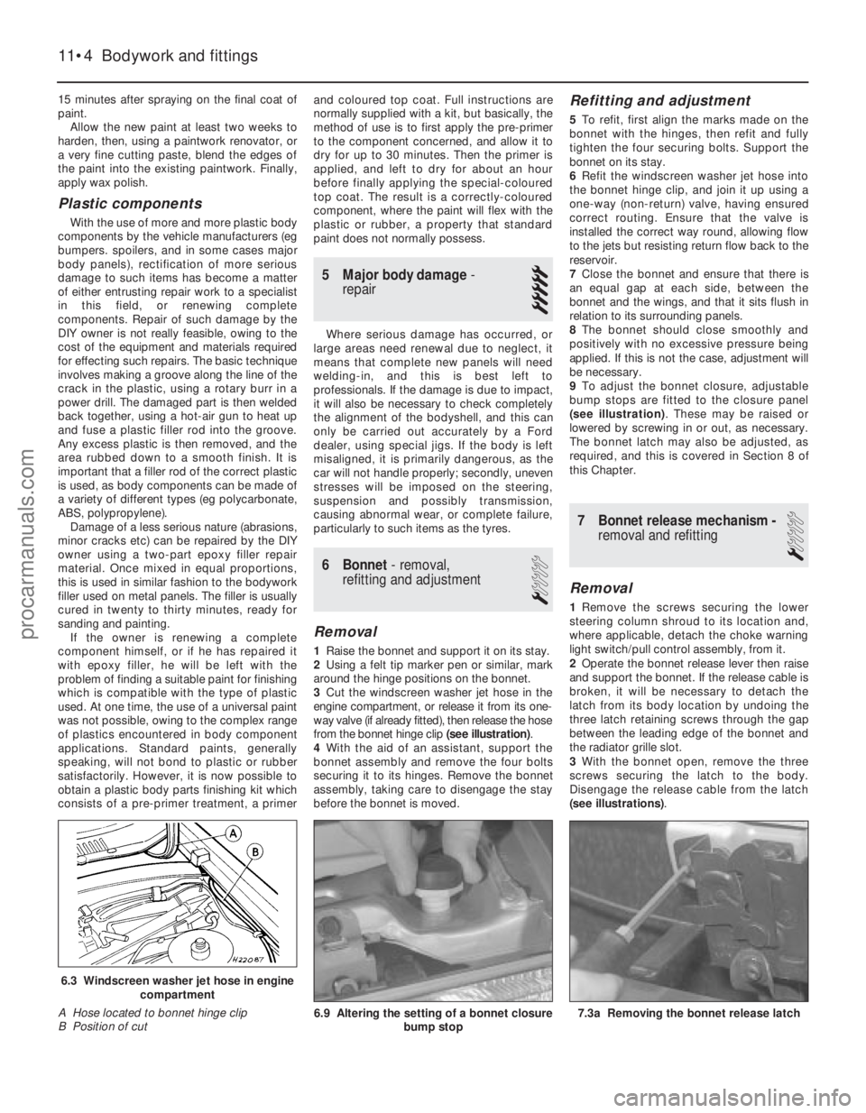
1 Raise the bonnet and support it on its stay.
2 Using a felt tip marker pen or similar, mark
around the hinge positions on the bonnet.
3 Cut the windscreen washer jet hose in the
engine compartment, or release it from its one-
way valve (if already fitted), then release the hose
from the bonnet hinge clip (see illustration).
4 With the aid of an assistant, support the
bonnet assembly and remove the four bolts
securing it to its hinges. Remove the bonnet
assembly, taking care to disengage the stay
before the bonnet is moved.
Refitting and adjustment
5 To refit, first align the marks made on the
bonnet with the hinges, then refit and fully
tighten the four securing bolts. Support the
bonnet on its stay.
6 Refit the windscreen washer jet hose into
the bonnet hinge clip, and join it up using a
one-way (non-return) valve, having ensured
correct routing. Ensure that the valve is
installed the correct way round, allowing flow
to the jets but resisting return flow back to the
reservoir.
7 Close the bonnet and ensure that there is
an equal gap at each side, between the
bonnet and the wings, and that it sits flush in
relation to its surrounding panels.
8 The bonnet should close smoothly and
positively with no excessive pressure being
applied. If this is not the case, adjustment will
be necessary.
9 To adjust the bonnet closure, adjustable
bump stops are fitted to the closure panel
(see illustration) . These may be raised or
lowered by screwing in or out, as necessary.
The bonnet latch may also be adjusted, as
required, and this is covered in Section 8 of
this Chapter.
7 Bonnet release mechanism - removal and refitting
1
Removal
1Remove the screws securing the lower
steering column shroud to its location and,
where applicable, detach the choke warning
light switch/pull control assembly, from it.
2 Operate the bonnet release lever then raise
and support the bonnet. If the release cable is
broken, it will be necessary to detach the
latch from its body location by undoing the
three latch retaining screws through the gap
between the leading edge of the bonnet and
the radiator grille slot.
3 With the bonnet open, remove the three
screws securing the latch to the body.
Disengage the release cable from the latch
(see illustrations) .
11•4 Bodywork and fittings
6.9 Altering the setting of a bonnet closure
bump stop
6.3 Windscreen washer jet hose in enginecompartment
A Hose located to bonnet hinge clip
B Position of cut
1595Ford Fiesta Remakeprocarmanuals.com
http://vnx.su
Page 216 of 296
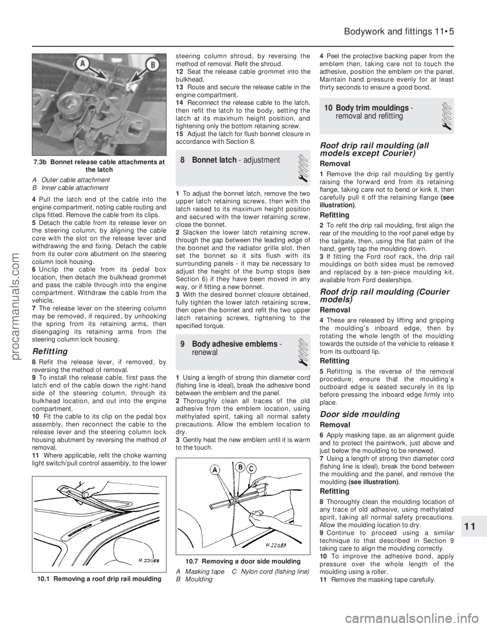
4Pull the latch end of the cable into the
engine compartment, noting cable routing and
clips fitted. Remove the cable from its clips.
5 Detach the cable from its release lever on
the steering column, by aligning the cable
core with the slot on the release lever and
withdrawing the end fixing. Detach the cable
from its outer core abutment on the steering
column lock housing.
6 Unclip the cable from its pedal box
location, then detach the bulkhead grommet
and pass the cable through into the engine
compartment. Withdraw the cable from the
vehicle.
7 The release lever on the steering column
may be removed, if required, by unhooking
the spring from its retaining arms, then
disengaging its retaining arms from the
steering column lock housing.
Refitting
8 Refit the release lever, if removed, by
reversing the method of removal.
9 To install the release cable, first pass the
latch end of the cable down the right-hand
side of the steering column, through its
bulkhead location, and out into the engine
compartment.
10 Fit the cable to its clip on the pedal box
assembly, then reconnect the cable to the
release lever and the steering column lock
housing abutment by reversing the method of
removal.
11 Where applicable, refit the choke warning
light switch/pull control assembly, to the lower steering column shroud, by reversing the
method of removal. Refit the shroud.
12
Seat the release cable grommet into the
bulkhead.
13 Route and secure the release cable in the
engine compartment.
14 Reconnect the release cable to the latch,
then refit the latch to the body, setting the
latch at its maximum height position, and
tightening only the bottom retaining screw.
15 Adjust the latch for flush bonnet closure in
accordance with Section 8.
8 Bonnet latch - adjustment
1
1To adjust the bonnet latch, remove the two
upper latch retaining screws, then with the
latch raised to its maximum height position
and secured with the lower retaining screw,
close the bonnet.
2 Slacken the lower latch retaining screw,
through the gap between the leading edge of
the bonnet and the radiator grille slot, then
set the bonnet so it sits flush with its
surrounding panels - it may be necessary to
adjust the height of the bump stops (see
Section 6) if they have been moved in any
way, or if fitting a new bonnet.
3 With the desired bonnet closure obtained,
fully tighten the lower latch retaining screw,
then open the bonnet and refit the two upper
latch retaining screws, tightening to the
specified torque.
9 Body adhesive emblems -
renewal
1
1 Using a length of strong thin diameter cord
(fishing line is ideal), break the adhesive bond
between the emblem and the panel.
2 Thoroughly clean all traces of the old
adhesive from the emblem location, using
methylated spirit, taking all normal safety
precautions. Allow the emblem location to
dry.
3 Gently heat the new emblem until it is warm
to the touch. 4
Peel the protective backing paper from the
emblem then, taking care not to touch the
adhesive, position the emblem on the panel.
Maintain hand pressure evenly for at least
thirty seconds to ensure a good bond.
10 Body trim mouldings -
removal and refitting
1
Roof drip rail moulding (all
models except Courier)
Removal
1 Remove the drip rail moulding by gently
raising the forward end from its retaining
flange, taking care not to bend or kink it, then
carefully pull it off the retaining flange (see
illustration) .
Refitting
2To refit the drip rail moulding, first align the
rear of the moulding to the roof panel edge by
the tailgate, then, using the flat palm of the
hand, gently tap the moulding down.
3 If fitting the Ford roof rack, the drip rail
mouldings on both sides must be removed
and replaced by a ten-piece moulding kit,
available from Ford dealerships.
Roof drip rail moulding (Courier
models)
Removal
4 These are released by lifting and gripping
the moulding’s inboard edge, then by
rotating the whole length of the moulding
towards the outside of the vehicle to release it
from its outboard lip.
Refitting
5 Refitting is the reverse of the removal
procedure; ensure that the moulding’s
outboard edge is seated securely in its lip
before pressing the inboard edge firmly into
place.
Door side moulding
Removal
6 Apply masking tape, as an alignment guide
and to protect the paintwork, just above and
just below the moulding to be renewed.
7 Using a length of strong thin diameter cord
(fishing line is ideal), break the bond between
the moulding and the panel, and remove the
moulding (see illustration) .
Refitting
8Thoroughly clean the moulding location of
any trace of old adhesive, using methylated
spirit, taking all normal safety precautions.
Allow the moulding location to dry.
9 Continue to proceed using a similar
technique to that described in Section 9
taking care to align the moulding correctly.
10 To improve the adhesive bond, apply
pressure over the whole length of the
moulding using a roller.
11 Remove the masking tape carefully.
Bodywork and fittings 11•5
7.3b Bonnet release cable attachments at
the latch
A Outer cable attachment
B Inner cable attachment
10.7 Removing a door side moulding
A Masking tape C Nylon cord (fishing line)
B Moulding
10.1 Removing a roof drip rail moulding
11
1595Ford Fiesta Remakeprocarmanuals.com
http://vnx.su
Page 231 of 296
31Remove the seat belt upper anchor bolt
cover and undo the bolt.
32 Carefully prise up the seat belt guide from
its trim panel location, and remove it from the
seat belt. Allow the seat belt to retract through
the trim panel, clamping a clothes peg, or
similar item, onto its end to prevent it being
fully wound into the retractor.
33 Manoeuvre the trim panel out from under
the scuff plate, slackening or removing the
rearward scuff plate retaining screws if
necessary.
Refitting
34 Engage the trim panel under the scuff
plate, and refit and tighten the scuff plate
retaining screws as necessary.
35 Pull the seat belt through the trim panel,
refit the guide and press the panel onto the
body to re-engage the trim clips.
36 Refit the upper seat belt anchor,
tightening the bolt to the specified torque, and
refit its cover. Ensure that the anchor is free to
rotate.
37 Refit the plastic stud and the screw to the
lower and upper rear corners of the trim,
respectively.
38 Refit the seat belt to the slide bar, then
refit the slide bar by reversing the method of
removal. Ensure that the seat belt is not
twisted as it is located on the slide bar, and
that the bolt is tightened to the specified
torque.
39 Refit the rear seat cushion by reversing
the method of removal.
40 Press the door aperture weatherstrip back
into position.
Load compartment trim panels
(Courier models)
Removal
41 Using either a trim clip releasing tool or a
screwdriver with a broad flat blade, and
protecting the paintwork and trim with a layer
of rag, extract the clips securing the panel and
withdraw it.
Refitting
42 Refitting is the reverse of the removal
procedure.
43 Parcel shelf support/
loudspeaker housing -
removal and refitting
3
Removal
1 Remove the rear seat belt and retractor unit
from the appropriate side of the vehicle, as
described in Section 41.
2 Disconnect the luggage compartment
(courtesy) light, where fitted, by prising the
light assembly from its location using a thin
flat-bladed screwdriver, then twist the
bulbholder anti-clockwise to remove.
3 Detach the loudspeaker, where fitted, by
removing its retaining screws, disengaging its
locating tags and disconnecting its multi-plug. 4
Fold the seat backrest forward. Remove the
parcel shelf support/rear loudspeaker housing
retaining screws, then manoeuvre it out from
under the quarter panel trim as necessary, to
clear the seat backrest catch striker pin.
Refitting
5 Refitting is a reversal of the removal
procedure.
44 Passenger grab handle -
removal and refitting
1
Removal
1 Carefully prise up the trim flaps on either
end of the handle to expose the two mounting
screws.
2 Undo the mounting screws and remove the
grab handle.
Refitting
3 Refitting is the reverse procedure to
removal.
45 Centre console -
removal and refitting
1
Removal
1 Disconnect the battery negative (earth) lead
(refer to Chapter 5A, Section 1).
2 Carefully prise up the console switches, as
necessary, using a flat-bladed screwdriver,
then disconnect their multi-plugs.
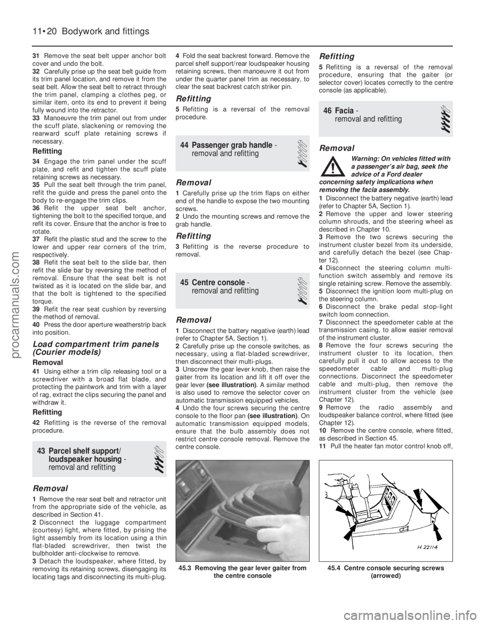
3 Unscrew the gear lever knob, then raise the
gaiter from its location and lift it off over the
gear lever (see illustration) . A similar method
is also used to remove the selector cover on
automatic transmission equipped vehicles.
4 Undo the four screws securing the centre
console to the floor pan (see illustration). On
automatic transmission equipped models,
ensure that the bulb assembly does not
restrict centre console removal. Remove the
centre console.
Refitting
5 Refitting is a reversal of the removal
procedure, ensuring that the gaiter (or
selector cover) locates correctly to the centre
console (as applicable).
46 Facia - removal and refitting
4
Removal
Warning: On vehicles fitted with
a passenger’s air bag, seek the
advice of a Ford dealer
concerning safety implications when
removing the facia assembly.
1 Disconnect the battery negative (earth) lead
(refer to Chapter 5A, Section 1).
2 Remove the upper and lower steering
column shrouds, and the steering wheel as
described in Chapter 10.
3 Remove the two screws securing the
instrument cluster bezel from its underside,
and carefully detach the bezel (see Chap-
ter 12).
4 Disconnect the steering column multi-
function switch assembly and remove its
single retaining screw. Remove the assembly.
5 Disconnect the ignition loom multi-plug on
the steering column.
6 Disconnect the brake pedal stop-light
switch loom connection.
7 Disconnect the speedometer cable at the
transmission casing, to allow easier removal
of the instrument cluster.
8 Remove the four screws securing the
instrument cluster to its location, then
carefully pull it out to allow access to the
speedometer cable and multi-plug
connections. Disconnect the speedometer
cable and multi-plug, then remove the
instrument cluster from the vehicle (see
Chapter 12).
9 Remove the radio assembly and
loudspeaker balance control, where fitted (see
Chapter 12).
10 Remove the centre console, where fitted,
as described in Section 45.
11 Pull the heater fan motor control knob off,
11•20 Bodywork and fittings
45.4 Centre console securing screws
(arrowed)45.3 Removing the gear lever gaiter fromthe centre console
1595Ford Fiesta Remakeprocarmanuals.com
http://vnx.su
Page 234 of 296
 Circuit(s) protected
1 3 . . . . . . . . . . . . . . . . . . . . . . . . . . . . . . . . . . . .\
. . . . . . . .")
12
1595Ford Fiesta Remake
Fuses - pre-1992 models
Main fuse board:
No Rating (amps) Circuit(s) protected
1 3 . . . . . . . . . . . . . . . . . . . . . . . . . . . . . . . . . . . .\
. . . . . . . . . . . . . Electronic engine control system
2 15 . . . . . . . . . . . . . . . . . . . . . . . . . . . . . . . . . . . .\
. . . . . . . . . . . . Interior light, cigarette lighter, clock and radio memory
3 20 . . . . . . . . . . . . . . . . . . . . . . . . . . . . . . . . . . . .\
. . . . . . . . . . . . Central locking system
4 30 . . . . . . . . . . . . . . . . . . . . . . . . . . . . . . . . . . . .\
. . . . . . . . . . . . Heated rear window element
5 10 . . . . . . . . . . . . . . . . . . . . . . . . . . . . . . . . . . . .\
. . . . . . . . . . . . Dim-dip lighting
6 10 . . . . . . . . . . . . . . . . . . . . . . . . . . . . . . . . . . . .\
. . . . . . . . . . . . Left-hand side lights and rear fog light
7 10 . . . . . . . . . . . . . . . . . . . . . . . . . . . . . . . . . . . .\
. . . . . . . . . . . . Right-hand side lights
8 10 . . . . . . . . . . . . . . . . . . . . . . . . . . . . . . . . . . . .\
. . . . . . . . . . . . Left-hand dipped beam
9 10 . . . . . . . . . . . . . . . . . . . . . . . . . . . . . . . . . . . .\
. . . . . . . . . . . . Right-hand dipped beam
10 15 . . . . . . . . . . . . . . . . . . . . . . . . . . . . . . . . . . . .\
. . . . . . . . . . . . Left-hand main beam and right-hand auxiliary driving light
11 15 . . . . . . . . . . . . . . . . . . . . . . . . . . . . . . . . . . . .\
. . . . . . . . . . . . Right-hand main beam and left-hand auxiliary driving light
12 20 . . . . . . . . . . . . . . . . . . . . . . . . . . . . . . . . . . . .\
. . . . . . . . . . . . Heater fan motor and reversing light
13 30 . . . . . . . . . . . . . . . . . . . . . . . . . . . . . . . . . . . .\
. . . . . . . . . . . . Radiator cooling fan motor
14 15 . . . . . . . . . . . . . . . . . . . . . . . . . . . . . . . . . . . .\
. . . . . . . . . . . . Front foglights (XR2i only)
15 15 . . . . . . . . . . . . . . . . . . . . . . . . . . . . . . . . . . . .\
. . . . . . . . . . . . Horn
16 20 . . . . . . . . . . . . . . . . . . . . . . . . . . . . . . . . . . . .\
. . . . . . . . . . . . Wiper motor and windscreen/tailgate washer pump
17 10 . . . . . . . . . . . . . . . . . . . . . . . . . . . . . . . . . . . .\
. . . . . . . . . . . . Brake stop lights, instrument illumination and instrument warning
18 30 . . . . . . . . . . . . . . . . . . . . . . . . . . . . . . . . . . . .\
. . . . . . . . . . . . Electrically operated windows
19 20 . . . . . . . . . . . . . . . . . . . . . . . . . . . . . . . . . . . .\
. . . . . . . . . . . . Electric fuel pump
20 10 . . . . . . . . . . . . . . . . . . . . . . . . . . . . . . . . . . . .\
. . . . . . . . . . . . Oxygen sensor (vehicles with catalytic converter)
21 10 . . . . . . . . . . . . . . . . . . . . . . . . . . . . . . . . . . . .\
. . . . . . . . . . . . Left-hand direction indicators
22 10 . . . . . . . . . . . . . . . . . . . . . . . . . . . . . . . . . . . .\
. . . . . . . . . . . . Right-hand direction indicators
Chapter 12
Body electrical systems
Air bag (driver’s side) - removal and refitting . . . . . . . . . . . . . . . . . . 28
Air bag (passenger’s side) - removal and refitting . . . . . . . . \
. . . . . . . 29
Air bag clock spring - removal and refitting . . . . . . . . . . . . . . . . . . . 31
Air bag control module - removal and refitting . . . . . . . . . . . . . . . . . 30
Anti-theft systems - general information . . . . . . . . . . . . . . . . . . . . . . 27
Battery, bulbs and fuses . . . . . . . . . . . . . . . . . . . .See
“Weekly checks”
Bulbs (exterior lights) - renewal . . . . . . . . . . . . . . . . . . . . . . . . . . . . . 5
Bulbs (interior lights) - renewal . . . . . . . . . . . . . . . . . . . . . . . . . . . . . 6
Cigarette lighter - removal and refitting . . . . . . . . . . . . . . . . . . . . . . 12
Clock - removal and refitting . . . . . . . . . . . . . . . . . . . . . . . . . . . . . . . 13
Electric window regulator motor - removal and refitting . . . . . . . . . . 20
Electrical fault-finding - general information . . . . . . . . . . . . . . . . . . . 2
Exterior light units - removal and refitting . . . . . . . . . . . . . . . . . . . . . 7
Fuses and relays - general information . . . . . . . . . . . . . . . . . . . . . . . 3
General information and precautions . . . . . . . . . . . . . . . . . . . . . . . . 1
Headlight and auxiliary light beam alignment - checking and
adjustment . . . . . . . . . . . . . . . . . . . . . . . . . . . . . . . . . . . .\
. . . . . . . 8
Horn - removal and refitting . . . . . . . . . . . . . . . . . . . . . . . . . . . . . . . 14 Instrument panel - removal and refitting . . . . . . . . . . . . . . . . . . . . . . 9
Instrument panel components - removal and refitting . . . . . . . . . . . 10
“Lights-on” warning module - removal and refitting . . . . . . . . . . . . . 26
Radio aerial - removal and refitting . . . . . . . . . . . . . . . . . . . . . . . . . . 25
Radio/cassette player - removal and refitting . . . . . . . . . . . . . . . . . . 22
Screen washer fluid level check . . . . . . . . . . . . . .See
“Weekly checks”
Speaker balance control joystick - removal and refitting . . . . . . . . . 24
Speakers - removal and refitting . . . . . . . . . . . . . . . . . . . . . . . . . . . . 23
Speedometer cable - removal and refitting . . . . . . . . . . . . . . . . . . . . 11
Switches - removal and refitting . . . . . . . . . . . . . . . . . . . . . . . . . . . . 4
Tailgate remote release motor - removal and refitting . . . . . . . . . . . 21
Tailgate wiper motor assembly - removal and refitting . . . . . . . . . . . 18
Windscreen wiper motor and linkage - removal and refitting . . . . . . 16
Windscreen wiper pivot shaft - removal and refitting . . . . . . . . . . . . 17
Windscreen/tailgate washer system components - removal and refitting . . . . . . . . . . . . . . . . . . . . . . . . . . . . . . . . . . . .\
. . . . . . . . . . 19
Wiper arms - removal and refitting . . . . . . . . . . . . . . . . . . . . . . . . . . 15
Wiper blade check . . . . . . . . . . . . . . . . . . . . . . . .See “Weekly checks”
12•1
Specifications Contents
Easy,suitable for
novice with little
experience Fairly easy,
suitable
for beginner with
some experience Fairly difficult,
suitable for competent
DIY mechanic
Difficult,
suitable for
experienced DIY
mechanic Very difficult,
suitable for expert DIY
or professional
Degrees of difficulty
54321
procarmanuals.com
http://vnx.su
Page 235 of 296
 Circuit(s) protected
23 - . . . . . . . . . . . . . . . . . . . . . . . . . . . . . . . . . . . .\
. . . . . . . . . . . . . Unused
24/25 10")
Additional fuses behind main fuse board:
NoRating (amps) Circuit(s) protected
23 - . . . . . . . . . . . . . . . . . . . . . . . . . . . . . . . . . . . .\
. . . . . . . . . . . . . Unused
24/25 10 . . . . . . . . . . . . . . . . . . . . . . . . . . . . . . . . . . . .\
. . . . . . . . . . . . Rear fog lights
26 15 . . . . . . . . . . . . . . . . . . . . . . . . . . . . . . . . . . . .\
. . . . . . . . . . . . Tailgate remote release
27/28 30 . . . . . . . . . . . . . . . . . . . . . . . . . . . . . . . . . . . .\
. . . . . . . . . . . . Heated windscreen
Fuses - 1992 models onward
Main fuse board:
Fuses 1 to 22 . . . . . . . . . . . . . . . . . . . . . . . . . . . . . . . . . . . .\
. . . . . . . . . Unchanged from pre-1992 models
Additional fuses behind main fuse board:
No Rating (amps) Circuit(s) protected
23* - . . . . . . . . . . . . . . . . . . . . . . . . . . . . . . . . . . . .\
. . . . . . . . . . . . . . Unused
23** 10 . . . . . . . . . . . . . . . . . . . . . . . . . . . . . . . . . . . .\
. . . . . . . . . . . . Rear fog lights
24* - . . . . . . . . . . . . . . . . . . . . . . . . . . . . . . . . . . . .\
. . . . . . . . . . . . . . Unused 24** 10 . . . . . . . . . . . . . . . . . . . . . . . . . . . . . . . . . . . .\
. . . . . . . . . . . . Rear fog lights
25 15 . . . . . . . . . . . . . . . . . . . . . . . . . . . . . . . . . . . .\
. . . . . . . . . . . . Tailgate remote release, anti-theft warning system
26 30 . . . . . . . . . . . . . . . . . . . . . . . . . . . . . . . . . . . .\
. . . . . . . . . . . . Heated windscreen
27 30 . . . . . . . . . . . . . . . . . . . . . . . . . . . . . . . . . . . .\
. . . . . . . . . . . . Heated windscreen
28* 20 . . . . . . . . . . . . . . . . . . . . . . . . . . . . . . . . . . . .\
. . . . . . . . . . . . Full-length sunroof
28** 30 . . . . . . . . . . . . . . . . . . . . . . . . . . . . . . . . . . . .\
. . . . . . . . . . . . Automatic transmission starter inhibitor
29 10 . . . . . . . . . . . . . . . . . . . . . . . . . . . . . . . . . . . .\
. . . . . . . . . . . . Air bag
* Pre-1994 models
** 1994 models onward
Relays (pre-1992 models)
Note: Relay locations and circuits controlled are liable to change from year t\
o year. Consult a Ford dealer, for specific information.
No Circuit(s) controlled
I . . . . . . . . . . . . . . . . . . . . . . . . . . . . . . . . . . . .\
. . . . . . . . . . . . . . Heated rear window
II . . . . . . . . . . . . . . . . . . . . . . . . . . . . . . . . . . . .\
. . . . . . . . . . . . . . Windscreen wiper delay
III . . . . . . . . . . . . . . . . . . . . . . . . . . . . . . . . . . . .\
. . . . . . . . . . . . . . CFi (fuel injection) delay relay
IV . . . . . . . . . . . . . . . . . . . . . . . . . . . . . . . . . . . .\
. . . . . . . . . . . . . . Not used on UK models
V . . . . . . . . . . . . . . . . . . . . . . . . . . . . . . . . . . . .\
. . . . . . . . . . . . . . Ignition switch
VI . . . . . . . . . . . . . . . . . . . . . . . . . . . . . . . . . . . .\
. . . . . . . . . . . . . . Automatic transmission starter inhibitor/electric fuel pump (bridge fitted to carburettor engines without automatic transmission)
VII . . . . . . . . . . . . . . . . . . . . . . . . . . . . . . . . . . . .\
. . . . . . . . . . . . . . Headlight main beam
VIII . . . . . . . . . . . . . . . . . . . . . . . . . . . . . . . . . . . .\
. . . . . . . . . . . . . . Dim-dip lighting
IX . . . . . . . . . . . . . . . . . . . . . . . . . . . . . . . . . . . .\
. . . . . . . . . . . . . . Not used on UK models
X . . . . . . . . . . . . . . . . . . . . . . . . . . . . . . . . . . . .\
. . . . . . . . . . . . . . Not used on UK models
XI . . . . . . . . . . . . . . . . . . . . . . . . . . . . . . . . . . . .\
. . . . . . . . . . . . . . Heated windscreen
XII . . . . . . . . . . . . . . . . . . . . . . . . . . . . . . . . . . . .\
. . . . . . . . . . . . . . Anti-lock braking system
A . . . . . . . . . . . . . . . . . . . . . . . . . . . . . . . . . . . .\
. . . . . . . . . . . . . . Idle speed control (automatic transmission) two-tone horn (where fitt\
ed)
B . . . . . . . . . . . . . . . . . . . . . . . . . . . . . . . . . . . .\
. . . . . . . . . . . . . . Not used on UK models
C . . . . . . . . . . . . . . . . . . . . . . . . . . . . . . . . . . . .\
. . . . . . . . . . . . . . Front foglights (XR2i)
D . . . . . . . . . . . . . . . . . . . . . . . . . . . . . . . . . . . .\
. . . . . . . . . . . . . . Headlight dipped beam
E . . . . . . . . . . . . . . . . . . . . . . . . . . . . . . . . . . . .\
. . . . . . . . . . . . . . Dim-dip lighting
Relays (1992 models onward)
Note: Relay locations and circuits controlled are liable to change from year t\
o year. Consult a Ford dealer, for specific information.
No Circuit(s) controlled
I . . . . . . . . . . . . . . . . . . . . . . . . . . . . . . . . . . . .\
. . . . . . . . . . . . . . Heated rear window
II . . . . . . . . . . . . . . . . . . . . . . . . . . . . . . . . . . . .\
. . . . . . . . . . . . . . Windscreen wiper delay
III . . . . . . . . . . . . . . . . . . . . . . . . . . . . . . . . . . . .\
. . . . . . . . . . . . . . CFi delay relay or EFi supply relay (fuel injection)
IV . . . . . . . . . . . . . . . . . . . . . . . . . . . . . . . . . . . .\
. . . . . . . . . . . . . . Not used on UK models
V . . . . . . . . . . . . . . . . . . . . . . . . . . . . . . . . . . . .\
. . . . . . . . . . . . . . Ignition switch
VI . . . . . . . . . . . . . . . . . . . . . . . . . . . . . . . . . . . .\
. . . . . . . . . . . . . . Automatic transmission starter inhibitor, anti-theft warning system
VII . . . . . . . . . . . . . . . . . . . . . . . . . . . . . . . . . . . .\
. . . . . . . . . . . . . . Headlight main beam
VIII . . . . . . . . . . . . . . . . . . . . . . . . . . . . . . . . . . . .\
. . . . . . . . . . . . . . Anti-lock braking system and/or dim-dip lighting
IX . . . . . . . . . . . . . . . . . . . . . . . . . . . . . . . . . . . .\
. . . . . . . . . . . . . . Not used on UK models
X . . . . . . . . . . . . . . . . . . . . . . . . . . . . . . . . . . . .\
. . . . . . . . . . . . . . Not used on UK models
XI . . . . . . . . . . . . . . . . . . . . . . . . . . . . . . . . . . . .\
. . . . . . . . . . . . . . Heated windscreen
XII . . . . . . . . . . . . . . . . . . . . . . . . . . . . . . . . . . . .\
. . . . . . . . . . . . . . Anti-lock braking system
A . . . . . . . . . . . . . . . . . . . . . . . . . . . . . . . . . . . .\
. . . . . . . . . . . . . . Idle speed control (automatic transmission) or two-tone horn (where f\
itted)
B . . . . . . . . . . . . . . . . . . . . . . . . . . . . . . . . . . . .\
. . . . . . . . . . . . . . Fuel pump
C . . . . . . . . . . . . . . . . . . . . . . . . . . . . . . . . . . . .\
. . . . . . . . . . . . . . Front foglights (XR2i, RS Turbo and RS 1800)
D . . . . . . . . . . . . . . . . . . . . . . . . . . . . . . . . . . . .\
. . . . . . . . . . . . . . Headlight dipped beam
E . . . . . . . . . . . . . . . . . . . . . . . . . . . . . . . . . . . .\
. . . . . . . . . . . . . . Dim-dip lighting
F . . . . . . . . . . . . . . . . . . . . . . . . . . . . . . . . . . . .\
. . . . . . . . . . . . . . Not used on UK models
12•2 Body electrical systems
1595Ford Fiesta Remakeprocarmanuals.com
http://vnx.su
Page 236 of 296
 . . . . . . . . . . . . . . . . . . . . . . . . . . . . . . . . . . . .\
. . . . . H4, 60/55
Sidelight (front) . . . . . . . . . . . . . . . . . . . . . . . . . . .")
BulbsWattage
Headlight (halogen) . . . . . . . . . . . . . . . . . . . . . . . . . . . . . . . . . . . .\
. . . . . H4, 60/55
Sidelight (front) . . . . . . . . . . . . . . . . . . . . . . . . . . . . . . . . . . . .\
. . . . . . . . 5
Direction indicators (main) . . . . . . . . . . . . . . . . . . . . . . . . . . . . . . . . . . . 21
Side direction indicator repeaters . . . . . . . . . . . . . . . . . . . . . . . . . . . . . . 5
Auxiliary driving and foglights (S and XR2i) . . . . . . . . . . . . . . . . . . . . . . H3, 55
Stop/tail light . . . . . . . . . . . . . . . . . . . . . . . . . . . . . . . . . . . .\
. . . . . . . . . . 21/5
Rear foglight . . . . . . . . . . . . . . . . . . . . . . . . . . . . . . . . . . . .\
. . . . . . . . . . 21
Reversing light . . . . . . . . . . . . . . . . . . . . . . . . . . . . . . . . . . . .\
. . . . . . . . 21
Number plate light . . . . . . . . . . . . . . . . . . . . . . . . . . . . . . . . . . . .\
. . . . . 10
Interior light . . . . . . . . . . . . . . . . . . . . . . . . . . . . . . . . . . . .\
. . . . . . . . . . . 10
Luggage compartment light . . . . . . . . . . . . . . . . . . . . . . . . . . . . . . . . . . 5
Instrument warning lights . . . . . . . . . . . . . . . . . . . . . . . . . . . . . . . . . . . .\
1.3 or 2.6
Panel illumination . . . . . . . . . . . . . . . . . . . . . . . . . . . . . . . . . . . .\
. . . . . . 1.3 or 2.6
Cigarette lighter illumination . . . . . . . . . . . . . . . . . . . . . . . . . . . . . . . . . . 1.4
Automatic transmission selector illumination . . . . . . . . . . . . . . . . . . . . . 2
Lubricants
Grease for windscreen wiper linkage and pivots . . . . . . . . . . . . . . . . . . To Ford specification SAM-1C-911-A
Torque wrench settingsNm lbf ft
Wiper motor to bracket . . . . . . . . . . . . . . . . . . . . . . . . . . . . . . . . . . . .\
. . 8 to 9 6 to 7
Wiper motor bracket to bulkhead/tailgate . . . . . . . . . . . . . . . . . . . . . . . 6 to 8 4 to 6
Windscreen wiper crank to driving shaft nut . . . . . . . . . . . . . . . . . . . . . 22 to 24 16 to 18
Windscreen/tailgate wiper arm retaining nut . . . . . . . . . . . . . . . . . . . . . 17 to 18 12 to 13
Windscreen wiper pivot shaft nut . . . . . . . . . . . . . . . . . . . . . . . . . . . . . . 9 to 12 7 to 9
Windscreen/tailgate washer reservoir securing bolts . . . . . . . . . . . . . . . 2.5 to 3.5 2 to 3
Headlight retaining bolt . . . . . . . . . . . . . . . . . . . . . . . . . . . . . . . . . . . .\
. 5.4 to 7.0 4 to 5
Tail light securing nuts . . . . . . . . . . . . . . . . . . . . . . . . . . . . . . . . . . . .\
. . 1.5 to 2.5 1 to 2
Auxiliary light retaining nut (S models) . . . . . . . . . . . . . . . . . . . . . . . . . . 6.8 to 9.2 5 to 7
Horn bracket retaining bolt . . . . . . . . . . . . . . . . . . . . . . . . . . . . . . . . . . . 24 to 33 18 to 24
Starter inhibitor switch . . . . . . . . . . . . . . . . . . . . . . . . . . . . . . . . . . . .\
. . 9 to 14 7 to 10
Body electrical systems 12•3
12
1595Ford Fiesta Remake
1 General information and
precautions
General information
The electrical system is of 12-volt negative
earth type. Power for the lights and all
electrical accessories is supplied by a
lead/acid battery, which is charged by the
engine-driven alternator.
This Chapter covers repair and service
procedures for the various electrical
components not associated with the engine.
Information on the battery, ignition system,
alternator, and starter motor can be found in
Chapter 5A and B.
All models from 1994 onwards are fitted
with a driver’s air bag, which is designed to
prevent serious chest and head injuries to the
driver during an accident. A similar bag for the
front seat passenger is also available. The
combined sensor and electronics for the air
bag is located next to the steering column
inside the vehicle, and contains a back-up
capacitor, crash sensor, decelerometer,
safety sensor, integrated circuit and
microprocessor. The air bag is inflated by a
gas generator, which forces the bag out of the module cover in the centre of the steering
wheel. A “clock spring” ensures that a good
electrical connection is maintained with the air
bag at all times - as the steering wheel is
turned in each direction, the spring winds and
unwinds.
An anti-theft alarm system is available on
later models, and is triggered if the vehicle is
broken into through the doors, bonnet, or
tailgate. The alarm will also be triggered if the
ignition or audio equipment is tampered with.
Additionally, from the 1994 model year
onwards, a Passive Anti-Theft System (PATS)
is fitted. This system, (which works
independently of the standard alarm) prevents
the engine from being started unless a
specific code, programmed into the ignition
key, is recognised by the PATS transceiver.
Precautions
Warning: Before carrying out
any work on the electrical
system, read through the
precautions given in “Safety
first!” at the beginning of this manual and
in Chapter 5A, Section 1.
Caution: Prior to working on any
component in the electrical system, the
battery negative lead should first be
disconnected, to prevent the possibility of electrical short-circuits and/or fires. If a
radio/cassette player with anti-theft
security code is fitted, refer to the
information given in the reference sections
of this manual before disconnecting the
battery.
2 Electrical fault-finding
-
general information
2
Note: Refer to the precautions given in
“Safety first!” and in Section 1 of this Chapter
before starting work. The following tests relate
to testing of the main electrical circuits, and
should not be used to test delicate electronic
circuits (such as engine management
systems), particularly where an electronic
control unit is used. Also refer to the
precautions given in Chapter 5A, Section 1.
General
1 A typical electrical circuit consists of an
electrical component, any switches, relays,
motors, fuses, fusible links or circuit breakers
related to that component, and the wiring and
connectors which link the component to both
the battery and the chassis. To help to
pinpoint a problem in an electrical circuit,
procarmanuals.com
http://vnx.su