1988 PONTIAC FIERO throttle adjustment
[x] Cancel search: throttle adjustmentPage 835 of 1825
6E3-A-32 5.OL (VIN F) & 5.7L (VIN 8) DRIVEABILITY AND EMISSIONS
FRONT VIEW TO MAT AND OF CONNECTOR COOLANT
SENSORS
452 BLK - D2 .
416 GUY - C14
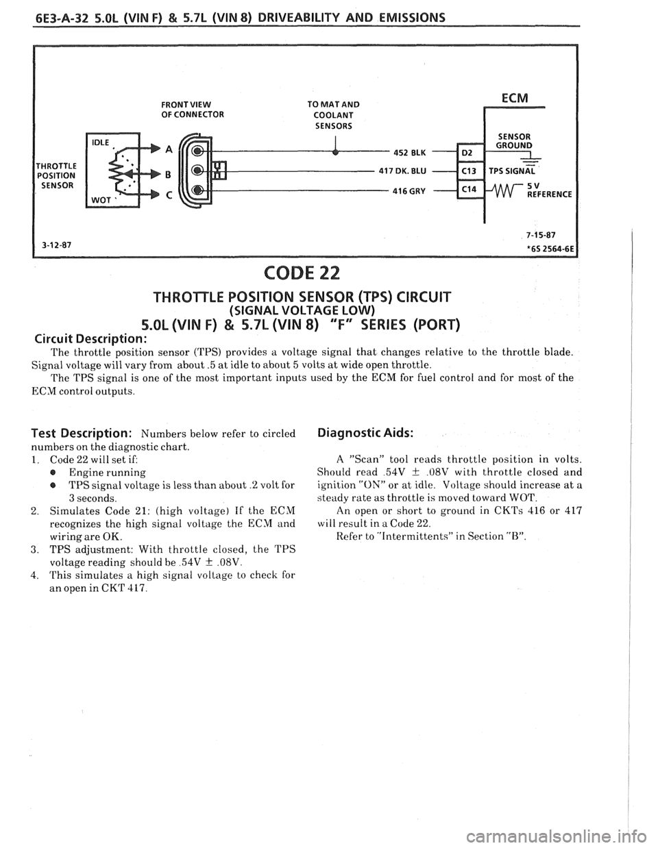
CODE 22
THROTLE POSITION SENSOR (WS) CIRCUIT
(SIGNAL VOLTAGE LOW)
5.OL (VIN F) & 5.7L (VIN 8) "F'YSERIES (PORT)
Circuit Description:
The throttle position sensor (TPS) provides a voltage signal that changes relative to the throttle blade.
Signal voltage will vary from about
.5 at idle to about 5 volts at wide open throttle.
The TPS signal is one of the most important inputs used by the
ECM for fuel control and for most of the
ECM control outputs.
Test Description: Numbers below refer to circled
numbers on the diagnostic chart.
1. Code22willsetiE
@ Engine running
TPS signal voltage is less than about
.% volt for
3 seconds.
2. Simulates
Code
21: (high voltage) If the ECM
recognizes the high signal voltage the ECM and
wiring are
OK.
3. TPS adjustment: With throttle closed, the TPS
voltage reading should be
54V f .08V.
4. This simulates a high signal voltage to check for
an open in CKT
417.
Diagnostic Aids:
A "Scan" tool reads throttle position in volts.
Should read
54V + .08V with throttle closed and
ignition
"ON" or at idle. Voltage should increase at a
steady rate as throttle is moved toward WOT.
An open or short to ground in
CKTs 416 or 417
will result in a Code 22.
Refer to "Intermittents" in Section
"B".
Page 871 of 1825
6E3-B-6 5.OL (VIN F) & 5.7L (VIN 8) DRIVEABILITY AND EMISSIONS
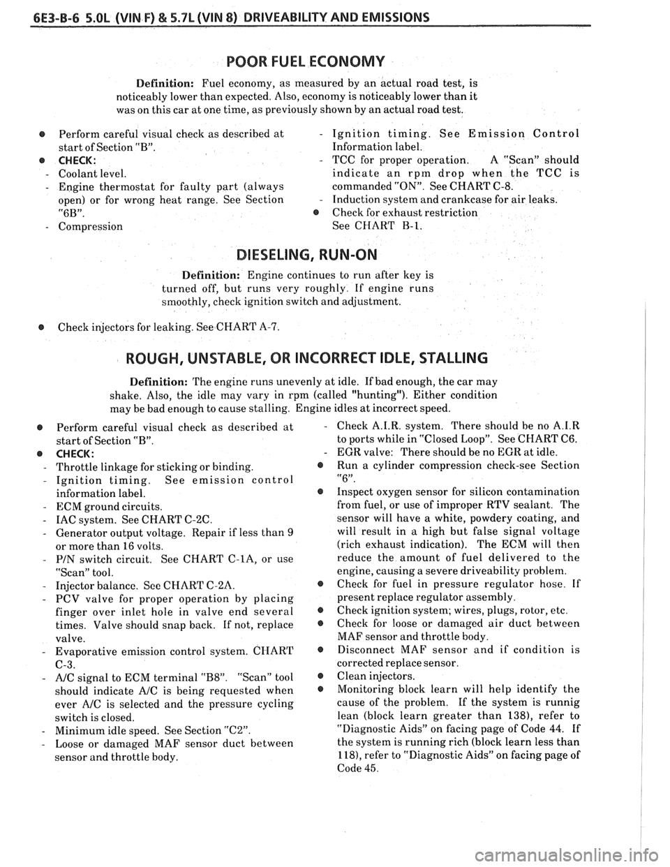
POOR FUEL ECONOMY
Definition: Fuel economy, as measured by an actual road test, is
noticeably lower than expected. Also, economy is noticeably lower than it
was on this car at one time, as previously shown by an actual road test.
@ Perform careful visual check as described at
start of Section "B".
@ CHECK:
- Coolant level.
- Engine thermostat for faulty part (always
open) or for wrong heat range. See Section
"6B".
- Compression
- Ignition timing. See Emission Control
Information label.
- TCC for proper operation. A "Scan" should
indicate an rpm drop when the TCC
is
commanded "ON". See CHART C-8.
- Induction system and crankcase for air leaks.
@ Check for exhaust restriction
See CHART
B-1.
DIESELING, RUN-ON
Definition: Engine continues to run after key is
turned off, but runs very roughly. If engine runs
smoothly, check ignition switch and adjustment.
@ Check injectors for leaking. See CHART A-7.
ROUGH, UNSTABLE, OR INCORRECT IDLE, STALLING
Definition: The engine runs unevenly at idle. If bad enough, the car may
shake. Also, the idle may vary in rpm (called "hunting"). Either condition
may be bad enough to cause stalling. Engine idles at incorrect speed.
@ Perform careful visual check as described at
start of Section "B".
e CHECK:
- Throttle linkage for sticking or binding.
- Ignition timing. See emission control
information label.
- ECM ground circuits.
- IAC system. See CHART C-2C.
- Generator output voltage. Repair if less than 9
or more than 16 volts.
- PIN switch circuit. See CHART C-lA, or use
"Scan" tool.
- Injector balance. See CHART C-2A.
- PCV valve for proper operation by placing
finger over inlet hole in valve end several
times. Valve should snap back. If not, replace
valve.
- Evaporative emission control system. CHART
C-3.
- A/C signal to ECM terminal "B8". "Scan" tool
should indicate
AIC is being requested when
ever
A/C is selected and the pressure cycling
switch is closed.
- Minimum idle speed. See Section "C2".
- Loose or damaged MAF sensor duct between
sensor and throttle body. Check
A.I.R. system. There should be no
A.1.R
to ports while in "Closed Loop". See CHART C6.
EGR valve: There should be no EGR at idle.
Run
a cylinder compression check-see Section
"6".
Inspect oxygen sensor for silicon contamination
from fuel, or use of improper RTV sealant. The
sensor will have a white, powdery coating, and
will result in a high but false signal voltage
(rich exhaust indication). The ECM will then
reduce the amount of fuel delivered to the
engine, causing a severe driveability problem.
Check for fuel in pressure regulator hose. If
present replace regulator assembly.
Check ignition system; wires, plugs, rotor, etc.
Check for loose or damaged air duct between
MAF sensor and throttle body.
Disconnect MAF sensor and if condition is
corrected replace sensor.
Clean injectors.
Monitoring block learn will help identify the
cause of the problem. If the system is runnig
lean (block learn greater than 1381, refer to
"Diagnostic Aids" on facing page of Code
44. If
the system is running rich (block learn less than
1 181, refer to "Diagnostic Aids" on facing page of
Code
45.
Page 878 of 1825
DRIVEABILITY AND EMISSIONS 5.OL (VIN F) & 5.7L (VIN 8) 6E3-C1-3
The MAT sensor signal is used by the ECM to
delay
EGR until the manifold air temperature reaches
about 5°C
(40°F).
A failure in the MAT sensor circuit should set
either a Code
23 or Code 25.
Oxygen (02) Sensor
(Figure
€3-4)
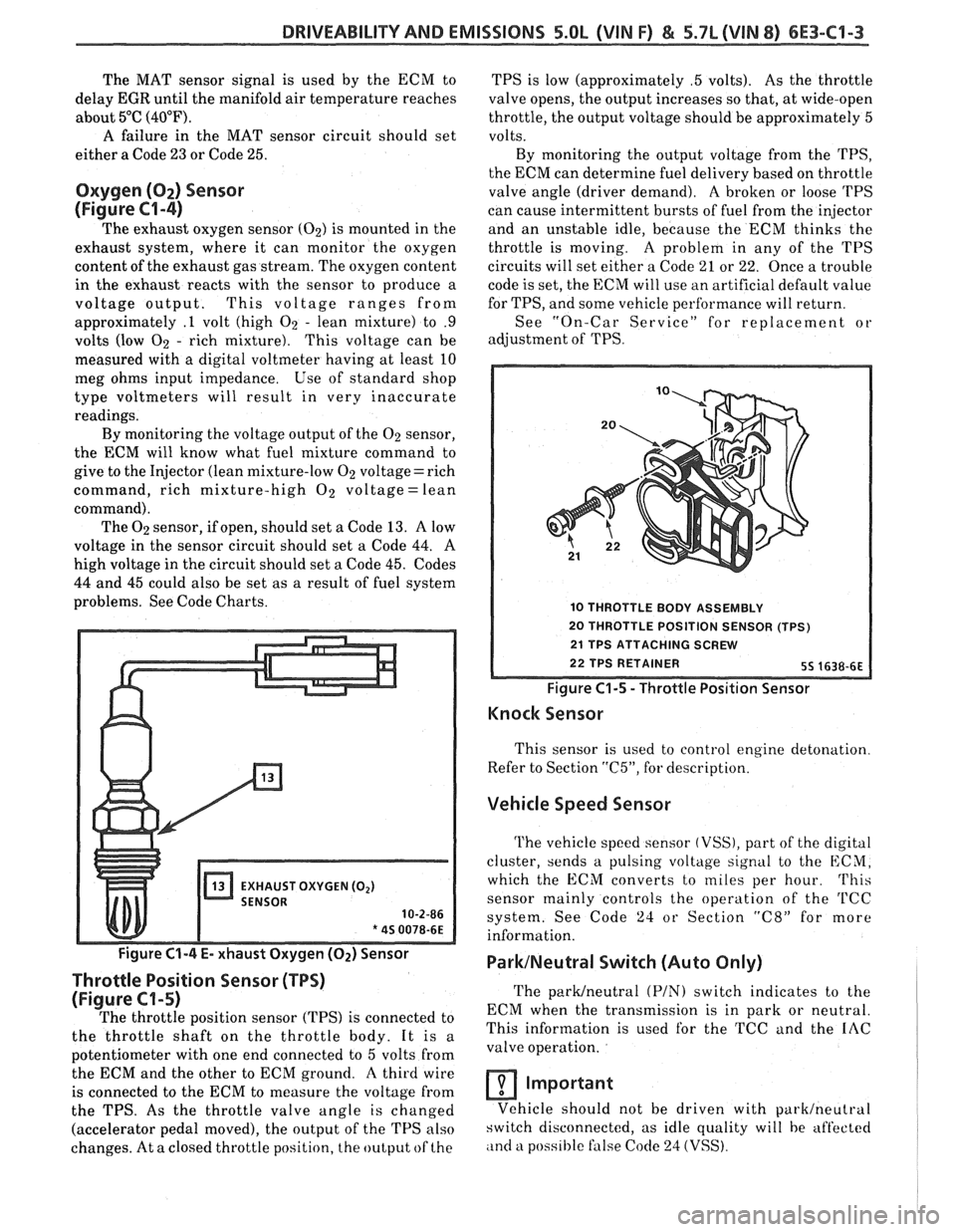
The exhaust oxygen sensor (02) is mounted in the
exhaust system, where it can monitor the oxygen
content of the exhaust gas stream. The oxygen content
in the exhaust reacts with the sensor to produce a
voltage output. This voltage ranges from
approximately
.l volt (high 02 - lean mixture) to .9
volts (low 02 - rich mixture). This voltage can be
measured with a digital voltmeter having at least 10
meg ohms input impedance. Use of standard shop
type voltmeters will result in very inaccurate
readings.
By monitoring the voltage output of the 02 sensor,
the ECM will know what fuel mixture command to
give to the Injector (lean mixture-low
02 voltage= rich
command, rich mixture-high
O2 voltage = lean
command). The
02 sensor, if open, should set a Code 13. A low
voltage in the sensor circuit should set a Code
44. A
high voltage in the circuit should set a Code 45. Codes
44 and 45 could also be set as a result of fuel system
problems. See Code Charts.
EXHAUST OXYGEN (02)
10-2-86
* 45 0078-6E
Figure C1-4 E- xhaust Oxygen (Oz) Sensor
Throttle Position Sensor (TPS)
(Figure C1-5)
The throttle position sensor (TPS) is connected to
the throttle shaft on the throttle body. It is a
potentiometer with one end connected to
5 volts from
the ECM and the other to ECM ground.
A third wire
is connected to the ECM to measure the voltage from
the TPS. As the throttle valve angle is changed
(accelerator pedal moved), the output of the TPS also
changes. At a closed throttle position, the output of the TPS
is low (approximately
.5 volts). As the throttle
valve opens, the output increases so that, at wide-open
throttle, the output voltage should be approximately
5
volts.
By monitoring the output voltage from the
TPS,
the ECM can determine fuel delivery based on throttle
valve angle (driver demand).
A broken or loose 'I'PS
can cause intermittent bursts of fuel from the injector
and an unstable idle, because the ECM thinks the
throttle is moving.
A problem in any of the TPS
circuits will set either a Code
21 or 22. Once a trouble
code is set, the ECM will use an artificial default value
for TPS, and some vehicle perfhrmance will return.
See "On-Car Service" for replacement or
adjustment of
TPS.
10 THROTTLE BODY ASSEMBLY
20 THROTTLE POSITION SENSOR (TPS)
Figure
C1-5 - Throttle Position Sensor
Knock Sensor
This sensor is used to control engine detonation
Refer to Section
"C5", for description.
Vehicle Speed Sensor
The vehicle speed sensor (VSS), part of the digital
cluster, sends a pulsing voltage signal to the ECM,
which the ECM converts to miles per hour.
This
sensor mainly controls the operation of the 'I'CC
system. See Code 24 or Section "C8" for more
information.
ParklNeutral Switch (Auto Only)
The parWneutra1 (PIN) switch indicates to the
ECM when the transmission is in park or neutral.
This information is used for the TCC and the
IAC
valve operation.
Important
Vehicle should not be driven with parklneutral
switch disconnected, as idle quality will be aft'ected
,ind a poss~hle false Code 24 (VSS).
Page 884 of 1825
DRIVEABILITY AND EMISSIONS 5.OL (VIN F) & 5.7L (WIN 8) 6E3-C1-9
Adjust
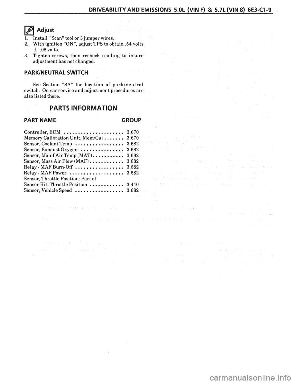
1. Install "Scan" tool or 3 jumper wires.
2. With ignition "ON", adjust TPS to obtain .54 volts
+ .08 volts.
3. Tighten screws, then recheck reading to insure
adjustment has not changed.
PARKINEUTRAL SWITCH
See Section "8A" for location of parklneutral
switch. On-car service and adjustment procedures are
also listed there.
PARTS INFORMATION
PART NAME CROUP
Controller, ECM ..................... 3.670
Memory Calibration Unit, MemICal ....... 3.670
Sensor, Coolant Temp ................. 3.682
Sensor, Exhaust Oxygen ............... 3.682
Sensor, Manif Air Temp (MAT). .......... 3.682
Sensor, Mass Air Flow (MAF) ............ 3.682
Relay - MAF Burn-Off ................. 3.682
Relay - MAF Power ................... 3.682
Sensor, Throttle Position: Part of
Sensor Kit, Throttle Position
............ 3.440
Sensor, Vehicle Speed ................. 3.682
Page 888 of 1825
DRIVEABILITY AND EMISSIONS 5.OL (VIN F) & 5.7L (VIN 8) 6E3-C2-1
SECTION C2
FUEL CONTROL SYSEENI
CONTENTS
GENERAL DESCRIPTION . . . . . . . . . . . . . . . . C2-1
PURPOSE ........................ C2-1
MODES OF OPERATION . . . . . . . . . . . . . . C2-2
Starting Mode . . . . . . . . . . . . . . . . . . . C2-2
Clear Flood Mode.. . . . . . . . . . . . . . . . C2-2
Run Mode.. . . . . . . . . . . . . . . . . . . . . . C2-2
Acceleration Mode.. . . . . . . . . . . . . . . C2-2
Deceleration Mode . . . . . . . . . . . . . . . C2-3
Battery Voltage Correction Mode . . . . . C2-3
Fuel Cutoff Mode . , . . . . . . . . . . . . . . . C2-3
FUEL CONTROL SYSTEM . . . . . . . . . . . . . . C2-3
Basic System Operation . . . . . . . . . . . . C2-3
Throttle Body Unit . . . . . . . . . . . . . . . . C2-3
Fuel Rail . . . . . . . . . . . . . . . . . . . . . . . C2-3
Fuel Injectors . . . . . . . . . . . . . . . . . . . . C2-3
Pressure Regulator . . . . . . . . . . . . . . . C2-4
IAC Valve . . . . . . . . . . . . . . . . . . . . . . . C2-4
Fuel Pump Electrical Circuit . . . . . . . . , C2-5
DIAGNOSIS
......................... C2-5
FUEL CONTROL SYSTEM . . . . . . . . . . . . . . C2-5
IDLE AIR CONTROL VALVE . . . .. 0.. . a. C2-5
FUEL SYSTEM PRESSURE TEST . .. . . . . . . C2-5
ON-CAR SERVICE
. . . . . . . . . . . . . . . . . . . . . C2-5
PORT FUEL INJECTION COMPONENTS . . . . C2-5
FUEL PRESSURE RELIEF PROCEDURE . . . . . C2-5
Plenum ........................ C2-5
FUEL RAlL ASSEMBLY . . . . . . . . . . . . . . . . C2-6
FUEL
RAlL SERVICE . . . . . . . . . . . . . . . . . . . C2-7
IDENTIFICATION . . . . . . . . . . . . . . . . . . . C2-7
UNlT SERVICE PROCEDURES .. . . . . . . . .. C2-7
COLD START TUBE & VALVE ASSEMBLY.. . C2-7
PARTS INFORMATION
. . . . . . . . . . . . . . . C2-9
FUEL PRESSURE CONNECTION ASSY. . . . . C2-10
FUEL INJECTORS (Rail Removed) . . . . . . . . C2-10
PRESSURE REGULATOR (Rail Removed) . . . C2-10
COLD START FUEL INJECTION SWITCH . . . C2-11
THROTTLEBODY ................... C2-11
THROTTLE BODY SERVICE IDENTIFICATION
. C2-12
UNlT REPAIR PROCEDURES . . . . . . . . . . . . C2-12
TPS Adjustment .............. C2-12
MINIMUM IDLE SPEED CHECK . . . . . . . . . . . C2-12
PARTSINFORMATION ................. C2-15
IDLE AIR C'NT' L VALVE ASSY & GASKET . . C2-15
CLEAN AIR COVER &GASKET . . . . . . . . . . C2-15
IDLE AIR CONTROUCOOLANT CVR. ASSY . C2-15
Throttle Body Removed From Engine . . C2-15
FUEL PUMP RELAY . . . . . . . . . . . . . .,. . . . C2-16
OIL PRESSURE SWITCH . . . . . . . . . . . . . . . C2-16
PARTS INFORMATION . . . . . . . . . . . . . . . . . C2-16
GENERAL DESCRIPTION
PURPOSE
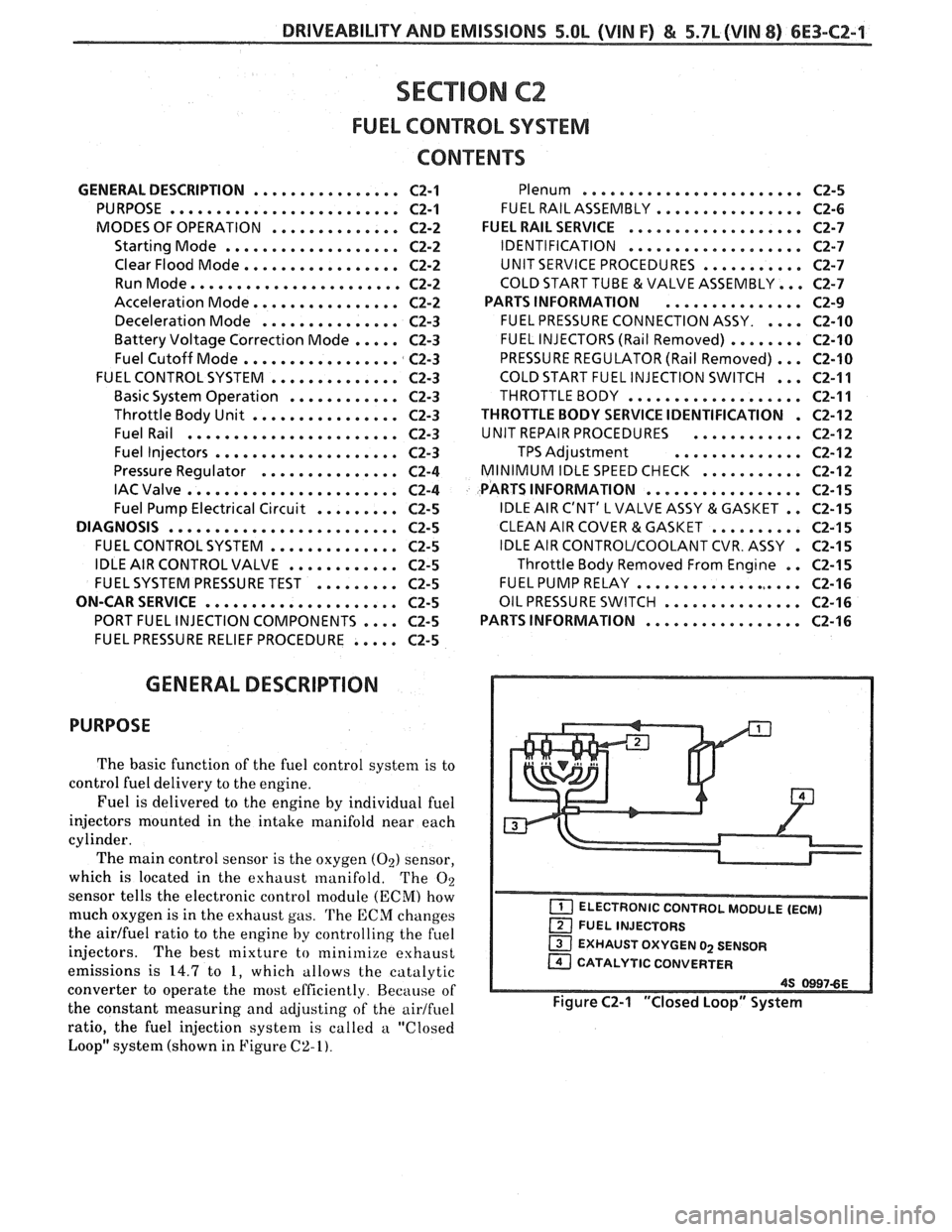
The basic function of the fuel control system is to
control fuel delivery to the engine.
Fuel is delivered to the engine by individual fuel
injectors mounted in the intake manifold near each
cylinder.
The main control sensor is the oxygen
(02) sensor,
which is located in the exhaust manifold. The
O2
sensor tells the electronic control module (ECM) how
much oxygen is in the exhaust gas.
The ECM changes
the
airlfuel ratio to the engine by controlling the fuel
injectors.
The best mixture to minimize exhaust
emissions is
14.7 to 1, which allows the catalytic
converter to operate the most efficiently. Because of
the constant measuring and adjusting of the
airlfuel
ratio, the fuel injection system is called a "Closed
Loop" system (shown in Figure
C2-I).
EXHAUST OXYGEN 02 SENSOR
CATALYTIC CONVERTER
Figure C2-1 "Closed Loop" System
Page 899 of 1825
6E3-C2-12 5.OL (VIN F) & 5.7L (VIN 8) DRIVEABILITY AND EMISSIONS
UNIT REPAIR PROCEDURES
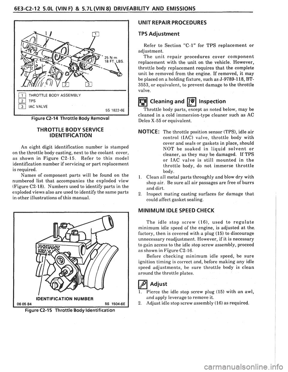
Figure C2-14 Throttle Body Removal
THROTTLE BODY SERVICE
IDENTIFICATION
An eight digit identification number is stamped
on the throttle body casting, next to the coolant cover,
as shown in Figure C2-15. Refer to this model
identification number if servicing or part replacement
is required.
Names of component parts will be found on the
numbered list that accompanies the exploded view
(Figure
C2-18). Numbers used to identify parts in the
exploded views also are used to identify the same parts
in other illustrations of this manual.
IDENTIFICATION NUMBER
Figure C2-15 Throttle Body Identification
TPS Adjustment
Refer to Section "C-1" for TPS replacement or
adjustment. The unit repair procedures cover component
replacement with the unit on the vehicle. However,
throttle body replacement requires that the complete
unit be removed from the engine. If removed, it may
be placed on a holding fixture, such as
5-9789-118, BT-
3553, or equivalent, to prevent damage to the throttle
valve.
Cleaning and a Inspection
Throttle body parts, except as noted below, may be
cleaned in a cold-immersion-type cleaner such
a; AC
Delco X-55 or equivalent.
NOTICE: The throttle position sensor (TPS), idle air
control
(IAC) valve, throttle body with
cover and seals or gaskets in place, should
NOT be soaked in liquid solvent or
cleaner, as they may be damaged. If TPS
or IAC valve is still mounted in the
throttle body, do not immerse throttle
body.
I. Clean all metal parts throughly and blow dry with
shop air. Be sure all air passages are free of burrs
and dirt.
2. Inspect mating casting surfaces for damage that
could affect gasket sealing.
MINIMUM IDLE SPEED CHECK
The idle stop screw (161, used to regulate
minimum idle speed of the engine, is adjusted at the.
factory, then is covered with a plug (15) to discourage
unnecessary readjustment. However, if it is necessary
to gain access to the idle stop screw assembly, proceed
as shown in Figure C2-16.
Before checking minimum idle speed, be sure
ignition timing is correct and, before making any idle
speed adjustments, be sure throttle body is clean
around the throttle plates.
Adjust
1. Pierce
the idle stop screw plug (15) with an awl,
and apply leverage to remove it.
2. Adjust idle stop screw assembly
(16) as required.
Page 902 of 1825
DRIVEABILITY AND EMISSIONS 5.OL (WIN F) & 5.7L (WIN 8) 6E3-C2-15
Important
No physical adjustment is made to the IAC
assembly after installation. IAC
valve resetting
occurs after reinstallation on the vehicle, and is
reset after the engine is started and then the
ignition turned "OFF".
THROTTLE BODY
PARTS INFORMATION
FIGURE CZ-18
PART NAME PART #
. Gasket Flange ......................... 1
Throttle Body Assembly .................. 10
Plug . Idle Stop Screw .................... 15
Screw Assembly - Idle Stop. ................ 16
Spring
- Idle Stop Screw ................... 17
Sensor - Throttle Position (TPS) ............. 20
Screw Assembly
- TPS Attaching ............ 21
Retainer
- TPS Attaching Screw ............. 22
Cover-CleanAir........................ 41
Screw Assembly
- Clean Air Cover
Attaching...
.......................... 42
Gasket
- Clean Air Cover .................. 43
IACVICoolant Cover Assembly ............. 61
Screw Assembly
- IACV Cover
Assembly to Throttle Body
................ 62
Gasket
- IACVICoolant Cover to
Throttle Body..
........................ 63
Valve Assembly
- ldle Air Control
(IAC) ................................ 70
Gasket
- IAC Valve Assembly .............. 71
CLEAN AIR COVER AND GASKET
ORemove or Disconnect
1. Clean
air cover attaching screw assemblies (42)
2. Clean air cover (41).
3. Clean air cover gasket (43).
@ Cover mounting surface to ensure a good seal.
Install and Connect
1. New clean air cover gasket (43) on throttle body
assembly
(10).
2. Clean air cover (41).
3. Clean air cover attaching screw assemblies (42).
61 IACVICOOLANT COVER ASSV 62 SCREW ASSY . IACV COVER ASSY TO THROrRE BODV 63 GASKET. IACV COOLANT COVER TO THROTTLE BODY 70 VALVE ASSV -IDLE AIR CONTROL 71 GASKET - IDLE AIR COHTROLVALVE
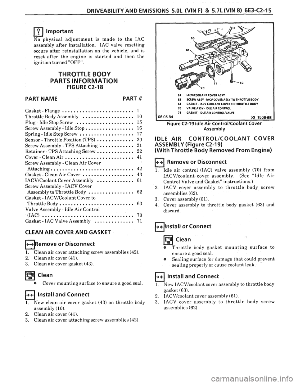
Figure C2-19 ldle Air Control/Coolant Cover
Assembly
IDLE AIR CONTRBLICOOLANT COVER
ASSEMBLY (Figure
CZ-19)
(With Throttle Body Removed From Engine)
a Remove or Disconnect
1. Idle
air control (IAC) valve assembly (70) from
IACVIcoolant cover assembly. (See "Idle Air
Control Valve and Gasket" instructions.)
2. IACV
cover assembly to throttle body screw
assemblies
(62).
3. Cover assembly (61).
4. Cover
assembly to throttle body gasket (63) and
discard.
alnstall or Connect
Clean
e Throttle body gasket mounting surface to
ensure a good seal.
e Sealing surface for damage that could prevent
sealing properly or
cause coolant leak.
a Install and Connect
1. New IACVIcoolant cover
assembly to throttle body
gasket
(63).
2. IACV/coolant cover assembly (61).
3. IACV
cover assembly to throttle body screw
assemblies
(62).
Page 960 of 1825
INDEX
SECTION
PAGE
MEM -Cal
General Description ................. C1-I
Diagnosis ......................... C1-4
A-60
Service
........................... C1-6
Functional Check
................... C1-7
Minimum
Idle Speed Adjustment ......... C2-12
Misses ............................. 8-5
Negative Backpressure Valve ............ C7-2
No ALDL Data
....................... A- 12
No "Service Engine Soon" Light
.......... A-10
.................... Oil Pressure Switch C2-16
Oxygen Sensor
General Description
.................. C1-3
......................... Diagnosis C1-5
A.24.54. 56
........................... Service C1-8
Park Neutral Switch
General Description
................. C1-3
Diagnosis
.......................... C1-10
C1-5
Service
........................... C1-9
Poor Fuel Economy
.................... B.6.
C5-4
Poor Performance
.................... C5-4
Positive Crankcase Ventilation (PCV)
General Description. Diagnosis
......... C13-1
Service
............................ C13-2
Pressure Regulator
.................... C2-4
........................ Quad Drivers C 1-4
..................... Reference Signal C1-5
.......................... Rough Idle B-6
RunMode .......................... C2-2
RunOn ............................. B-6
SECTION PAGE
................... Sensor Information C1-2-9
"Service Engine Soon" Light On Steady .... A- 12
................... Setting Timing ... . C4-2
.......................... Shift Light C8-6
Sluggish
............................ B-4
......................... Spark Knock B-4
........................ Speed Sensor C8-2
.................. Speedo Buffer Sensor C8-4
Spongy
............................. B-4
............................ Stalling B-6
........................ Starting Mode C2-2
........................... Stumble B-3
Surges
............................. B-3
.................. System Over Voltage A-60
Throttle Body Unit
................. General Description C2-3
........................... Service C2-11
Throttle Position Sensor
................. General Description C1-3
......................... Diagnosis C1-5
A-30
....................... Adjustments C2-12
........................... Service C1-8
Transmission Converter Clutch TCC System
.................. General Description C8-1
......................... Diagnosis C8.2. 4
U
........................ Unstable Idle B-6
V
...................... Vapor Canister C3-1
Vehicle Speed Sensor
.................. General Description C1-3
.......................... Diagnosis C1-5
A-36
Vehicle Anti-Theft System (VATS)
................. General Description A-58
......................... Diagnosis A-59
W
...................... Wiring Diagrams A-3
................... Won't Flash Code 12 A-
12
Sag
.................+............. B-3
......................... "Scan" Data A-8