1988 PONTIAC FIERO width
[x] Cancel search: widthPage 401 of 1825
BA3-22 V-8 ENGINE
5. On the edge of gaging plastic envelope there is a
graduated scale which is correlated in
thousandths of an inch. Without removing the
gaging plastic, measure its compressed width (at
the widest point) with the graduations on the
gaging plastic envelope (fig. 6A3-40).
Normally main bearing journals wear evenly and
are not out-of-round. However, if a bearing is
being fitted to an out-of-round journal
(.00lU
max.), be sure to fit to the maximum diameter of
the journal: If the bearing is fitted to the
minimum diameter and the journal is
out-of-round
.001", interference between the
bearing and journal will result in rapid bearing
failure. If the flattened gaging plastic tapers
toward the middle or ends, there is a difference
in clearance indicating taper, low spot or other
irregularity of the bearing or journal. Be sure to
measure the journal with a micrometer if the
flattened gaging plastic indicates more than
.00lV
difference.
6. If the bearing clearance is within specifications,
the bearing insert is satisfactory. If the clearance'
is not within specifications, replace the insert.
Always replace both upper and lower inserts as
a unit.
If a new bearing cap is being installed and
clearance is less than
.00 1 ", inspect for burrs or
nicks; if none are found then install shims as
required.
I MEASURE END PLAY
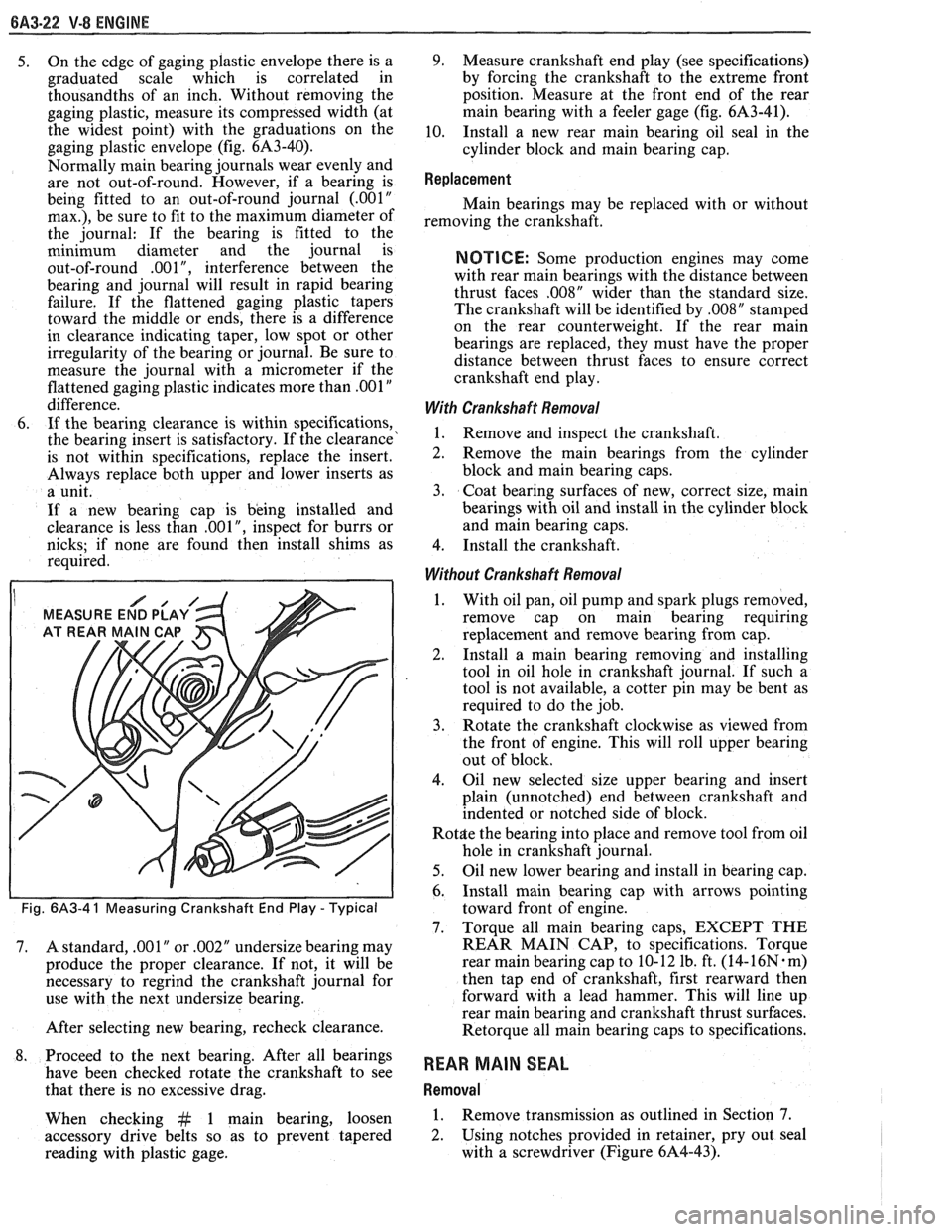
Fig. 6A3-4 1 Measuring Crankshaft End Play - Typical
7. A standard, .001" or .002" undersize bearing may
produce the proper clearance. If not, it will be
necessary to regrind the crankshaft journal for
use with the next undersize bearing.
After selecting new bearing, recheck clearance.
8. Proceed to the next bearing. After all bearings
have been checked rotate the crankshaft to see
that there is no excessive drag.
When checking
&t 1 main bearing, loosen
accessory drive belts so as to prevent tapered
reading with plastic gage.
9. Measure crankshaft end play (see specifications)
by forcing the crankshaft to the extreme front
position. Measure at the front end of the rear
main bearing with a feeler gage (fig.
61\3-41),
10. Install a new rear main bearing oil seal in the
cylinder block and main bearing cap.
Replacement
Main bearings may be replaced with or without
removing the crankshaft.
NOTICE: Some production engines may come
with rear main bearings with the distance between
thrust faces
,008" wider than the standard size.
The crankshaft will be identified by
,008" stamped
on the rear counterweight. If the rear main
bearings are replaced, they must have the proper
distance between thrust faces to ensure correct
crankshaft end play.
With Crankshaft Removal
1. Remove and inspect the crankshaft.
2. Remove the main bearings from the cylinder
block and main bearing caps.
3. Coat bearing surfaces of new, correct size, main
bearings with oil and install in the cylinder block
and main bearing caps.
4. Install the crankshaft.
Without Crankshaft Removal
1. With oil pan, oil pump and spark plugs removed,
remove cap on main bearing requiring
replacement and remove bearing from cap.
2. Install a
main bearing removing and installing
tool in oil hole in crankshaft journal. If such a
tool is not available, a cotter pin may be bent as
required to do the job.
3. Rotate the crankshaft clockwise as viewed from
the front of engine. This will roll upper bearing
out of block.
4. Oil new selected size upper bearing and insert
plain (unnotched) end between crankshaft and
indented or notched side of block.
Rot$e the bearing into place and remove tool from oil
hole in crankshaft journal.
5. Oil new lower bearing and install in bearing cap.
6. Install main bearing cap with arrows pointing
toward front of engine.
7. Torque all main bearing caps, EXCEPT THE
REAR MAIN CAP, to specifications. Torque
rear main bearing cap to 10- 12 lb. ft. (14-
16N. m)
then tap end of crankshaft, first rearward then
forward with a lead hammer. This will line up
rear main bearing and crankshaft thrust surfaces.
Retorque all main bearing caps to specifications.
REAR MAIN SEAL
Removal
1. Remove transmission as outlined in Section 7.
2. Using notches provided
in retainer, pry out seal
with a screwdriver (Figure 6A4-43).
Page 409 of 1825
6A3-30 V-8 ENGINE
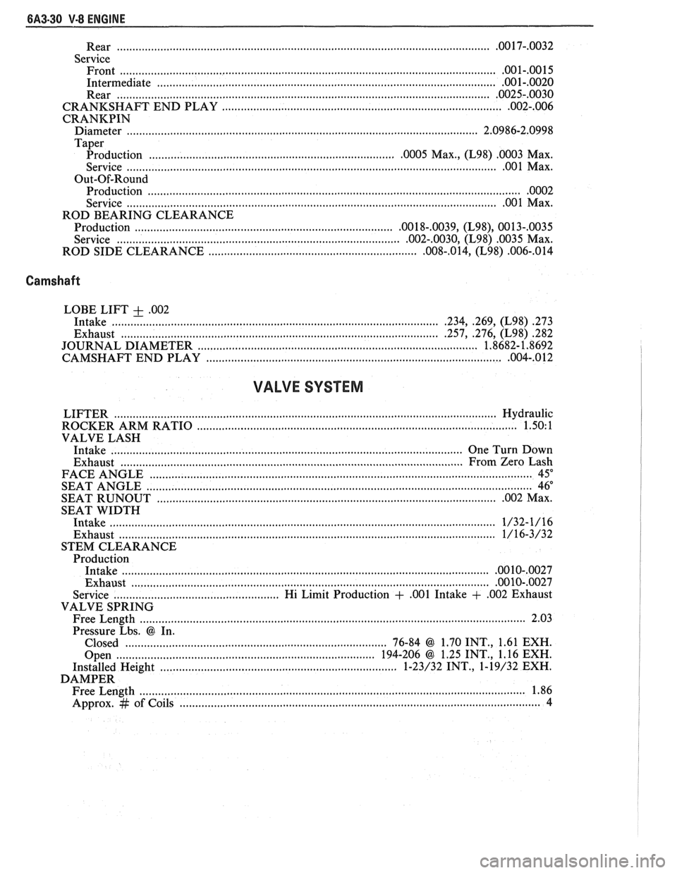
.............................................................................................. Rear ................... .. .OO 17-.0032
Service Front
......................................................................................................................... .001-.0015
Intermediate ............................................................................................................ .001-.0020
Rear ....................................................................................................................... .0025-.0030
............................................................. CRANKSHAFT END PLAY ....................... .. .002-.006
CRANKPIN
Diameter ........................... .. ................................................................................. 2.0986-2.0998
Taper
................................................ Production ....................... .. .0005 Max., (L98) .0003 Max.
............................................................................. Service ............................ .. ...... .... .OO 1 Max.
Out-Of-Round Production
....................................................................................................................... .0002
................................................................................... Service ............................ .. .00 1 Max.
ROD BEARING CLEARANCE
Production
................................................................................ ,0018-.0039, (L98), 0013-,0035
................................................... Service ................................. ....... .002-.0030, (L98) .0035 Max.
ROD SIDE CLEARANCE
............................................................... ,008-.014, (L98) .006-,014
Camshaft
LOBE LIFT + .002
Intake ..................... .. .......................................................................... .234, .269, (L98) .273
Exhaust ................................................................................................. .257, .276, (L98) 282
....................................................... JOURNAL DIAMETER .................... .... ... 1.8682- 1.8692
................................................................. CAMSHAFT END PLAY ...................... .. ,004-.012
VALVE SYSTEM
LIFTER ......................................................................................................................... Hydraulic
ROCKER ARM RATIO
................................................................................................. 1.50: 1
VALVE LASH
Intake
............................................................................................................. One Turn Down
Exhaust
..................................... ... ...................................................................... From Zero Lash
FACE ANGLE
..................... ... ............................................................................................. 45"
.......................................................................................................................... SEAT ANGLE 46"
SEAT
RUNOUT ............................................................................................................. .002 Max.
SEAT WIDTH
Intake
.................................... .... .................................................................................... 1/32-1/16
Exhaust ......................................................................................................................... 1/16-3/32
STEM CLEARANCE
Production
Intake
.................................................................................................................... .0010-,0027
Exhaust .................................................................................................................. .00 10-.0027
Service .................................................. Hi Limit Production + ,001 Intake + ,002 Exhaust
VALVE SPRING
Free Length
......................................................................................................................... 2.03
Pressure Lbs.
@ In.
Closed
.................................................................................... 76-84 @ 1.70 INT., 1.61 EXH.
Open
............................................................................... 194-206 @ 1.25 INT., 1.16 EXH.
Installed Height
....................... .. ............................................. 1-23/32 INT., 1-19/32 EXH.
DAMPER Free Length
................... .. ............................................................................................... 1.86
Approx.
# of Coils .................................................................................................................. 4
Page 580 of 1825

DRIVEABILITY AND EMISSIONS - 5.OL (\/IN El 6EZ-CZ-5
sent to the ECM. The ECM then increases the injector
base pulse width, permitting increased fuel flow.
As the throttle valve rotates in response to
movement of the accelerator pedal, the throttle shaft
transfers this rotational movement to the
'I'PS. A
potentiometer (variable resistor) within the TPS
assembly changes its resistance (and voltage drop) in
proportion to throttle movement.
By applying a reference voltage (5.0 volts) to the
TPS input, a varying voltage (reflecting throttle
position) is available at the TPS output. For example,
approximately 2.5 volts results from a 50% throttle
valve opening (depending on TPS calibration). The
voltage output from the TPS assembly is routed to the
ECM for use in determining throttle position.
FUEL PUMP
The fuel pump is a turbine type, low pressure
electric pump, mounted in the fuel tank. Fuel
is
pumped at a positive pressure (above 62
kPa or 9 psi)
from the fuel pump through the in-line filter to the
pressure regulator in the TBI assembly Excess
fuel is
returned to the fuel tank through the fuel return line.
The fuel pump is attached to the fuel gage sender
assembly. A fuel strainer is attached to the fuel pump
inlet line and prevents dirt particles from entering the
fuel line and tends to separate
water from the fuel
Vapor lock problems are reduced when using an
electric
pump because the fuel is pushed from the tank
under pressure rather than being pulled
under
vacuum, a condition that produces vapor.
An inoperative fuel pump would cause
a. no start
condition. A fuel pump which does not provide enough
pressure can result in poor performance. (See "Fuel
System Pressure Test" procedure).
FUEL PUMP ELECTRICAL CIRCUIT
When the key is first turned "ON" without the
engine running, the ECM turns the
Fuel pump relay
"ON" for two seconds. This builds
up the fuel pressure
quickly. If the engine is not started within two
seconds, the
ECM shuts the fuel pump "OFF" and
waits until the engine starts. As soon as the engine is
cranked, the ECM turns the relay
"ON" and runs the
fuel pump.
As a backup system to the fuel pump relay, the
fuel pump can also be turned on
by the oil pressure
switch. The oil pressure sender has two circuits
internally. One operates the oil pressure indicator or
gage in the instrument cluster,
itnd the other is
anormally open switch which closes when oil pressure
reaches about 28
kPa (4 psi). If the fuel pump relay
fails, the oil pressure switch will run the fuel pump. An
inoperative fuel pump relay can result in long
cranking times, particularly if the engine is cold. The
oil pressure switch will turn on the fuel pump as soon
as oil pressure
reaches about 28 kPa (4 psi).
FUEL CONTROL
Always start with the "Diagnostic Circuit Check"
in Section
"6E2-A". This will reduce diagnosis time
and prevents unnecessary replacement of parts. The
information in this check will direct diagnosis
concerning "Engine
Crunlis But Won't Run" and the
"Fuel Control System," Section
"6E2-C2", including
diagnosis of an injector, pressure regulator,
fuel pump,
fuel
pump relay, and oil pressure switch.
Idle Air Control (IAC) Valve
A "Scan" tool reads IAC position in steps, calletl
"Counts." "0" steps indicates the ECM is commanding
the
IAC to be driven in, to a fully seiltetl position
(minimum idle air).
The higher the number steps, the
more idle air being allowed to pass
by the IAC valve.
cnose Refer to CHART C-2C for information to cliil,
the function of the IAC valve.
Driva bility
Refer to Section "B" for driveability symptoms
related to the fuel control.
ON-VEHICLE SERVICE
GENERAL SEWVICE INFORMATION
CAUTION:
e To prevent personal injury or damage to the
vehicle
as the result sf an accidental start,
disconnect and reconnect the negative
battery cable before and after service is
performed.
@ Also, catch any fuel that leaks out when
disconnecting the fuel lines, by covering the
fittings with
a shop cloth. Place the cloth in
an approved container when work is
complete.
The 'FBI unit repair procedures cover component
replacement with the unit on the vehicle,
tIowever,
throttle body replacement requires that the complete
unit
be removed from the enginc.
Page 620 of 1825
DRIVEABILITY AND EMISSIONS - 5.OL (VIN E) 6E2-C7-1
SECTION C7
EXHAUST GAS RECIRCULAVON (EGR) SYSEENO
GENERAL DESCRIPTION ...............
........................ PURPOSE
OPERATION
......................
EGR CONTROL .....................
...... NEGATIVE BACKPRESSURE VALVE
.......... EGR VALVE IDENTIFICATION
RESULTS OF INCORRECT OPERATION
. . , .
CONTENTS
......................... C7-1 DIAGNOSIS C7-2
..................... C7-1 ON-CAR SERVICE C7-2
....................... C7-1 EGRVALVE C7-2
............. C7-1 EGR Manifold Passage C7-2
C7-1
EGR CONTROL SOLENOID ............. C7-3
C7-2 PARTS INFORMATION
................. C7-3
C7-2
GENERAL DESCRIPTION
PURPOSE
The EGR system is used to lower NO, (oxides of
nitrogen) emission levels caused by high combustion
temperatures.
It does this by decreasing combustion
temperature. The main element of the system is an
EGR valve
operated by vacuum, and mounted on the intake
manifold. The EGR valve feeds small amounts of exhaust
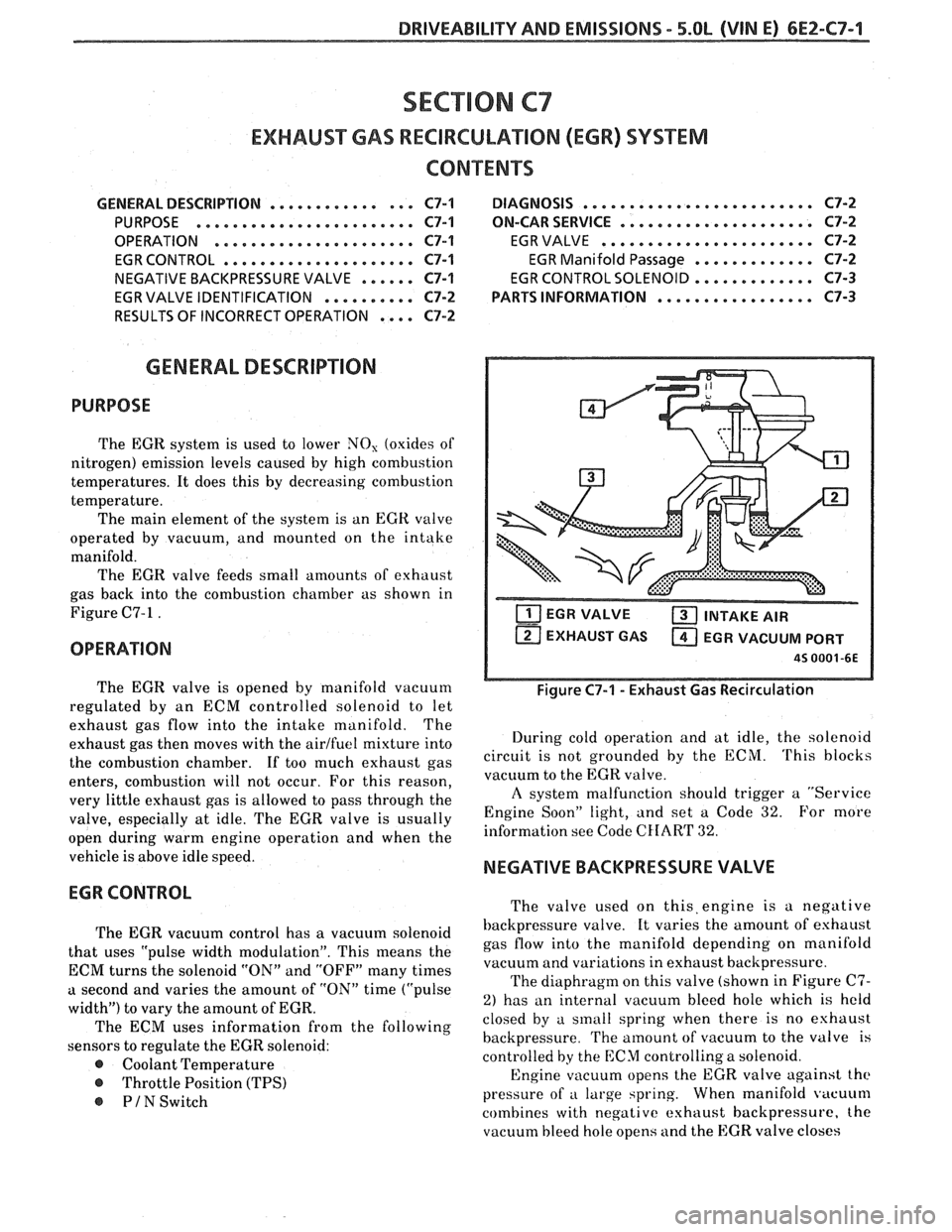
gas back into the combustion chamber as shown in
Figure C7-1
.
OPERATION
The EGR valve is opened by manifold vacuum
regulated by an ECM controlled solenoid to let
exhaust gas flow into the intake manifold. The
exhaust gas then moves with the
airlfuel mixture into
the combustion chamber.
If too much exhaust gas
enters, combustion will not occur. For this reason,
very little exhaust gas is allowed to pass through the
valve, especially at idle. The EGR valve is usually
open during warm engine operation and when the
vehicle is above idle speed.
EGR CONTROL
The EGR vacuum control has a vacuum solenoid
that uses "pulse width modulation". This means the
ECM turns the solenoid "ON" and "OFF" many times
a second and varies the amount of "ON" time ("pulse
width") to vary the amount of EGR.
The ECM uses information from the following
sensors to regulate the EGR solenoid:
@ Coolant Temperature
@ Throttle Position (TPS)
PIN Switch
T'IT] EGR VALVE a INTAKE AIR
EXHAUST GAS
a EGR VACUUM PORT
45 0001 -6E
Figure C7-1 - Exhaust Gas Recirculation
During cold operation and at idle, the solenoid
circuit is not grounded by the ECM.
'I'his blocks
vacuum to the EGR valve.
A system malfunction should trigger a "Service
Engine Soon" light, and set a Code
32. For more
information see Code
CHAR'I' 32.
NEGATIVE BACKPRESSURE VALVE
The valve used on this,engine is a negative
backpressure valve. It varies the amount of eshaust
gas flow into the manifold depending on manifold
vacuum and variations in exhaust backpressure.
The diaphragm on this valve (shown in Figure
C7-
2) has an internal vacuum bleed hole which is held
closed by a sinall spring when there is no eshaust
backpressure.
The amount of vacuum to the valve is
controlled
by the ECM controlling a solenoid.
Engine vacuum opens the EGR valve against
the
pressure of a large spring. When manifold vacuum
combines with negative exhaust backpressure, the
vacuum bleed hole opens and the EGR valve closes
Page 661 of 1825
DIAGNOSTIC CIRCUIT CHECK
The diagnostic circuit check is an organized approach to identifying a problem created by an electronic
engine control system malfunction. It
must be the starting point for any driveability complaint diagnosis,
because it directs the service technician to the next logical step in diagnosing the complaint.
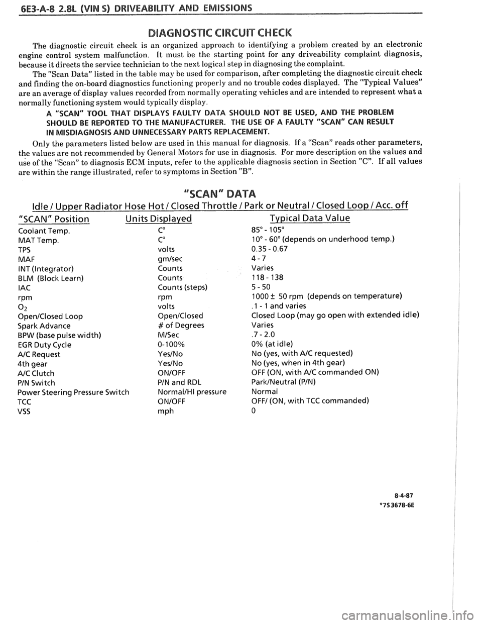
The "Scan Data" listed in the table may be used for comparison, after completing the diagnostic circuit check
and finding the on-board diagnostics functioning properly and no trouble codes displayed. The "Typical Values"
are an average of display values recorded from normally operating vehicles and are intended to represent what a
normally functioning system would typically display.
A "SCAN" TOOL THAT BiSPLAYS FAULTY DATA SHOULD NOT BE USED, AND THE PROBLEM
SHOULD BE REPORTED
TO THE MANUFACTURER. THE USE OF A FAULTY "SCAN" CAN RESULT
IN MISDIAGNOSIS AND UNNECESSARY PARTS REPLACEMENT.
Only the parameters listed below are used in this manual for diagnosis. If a "Scan" reads other parameters,
the values are not recommended by General Motors for use in diagnosis. For more description on the values and
use of the "Scan" to diagnosis
ECM inputs, refer to the applicable diagnosis section in Section "C". If all values
are within the range illustrated, refer to symptoms in Section
"B".
""SCAN" DATA
Coolant Temp. CO 85" - 105"
MAT Temp. C0 10" - 60" (depends on underhood temp.)
TPS
volts 0.35 - 0.67
MAF
gmlsec 4-7
INT (Integrator) Counts Varies
BLM (Block Learn) Counts 118- 138
IAC Counts (steps) 5-50
rPm rPm 1000 ? 50 rpm (depends on temperature)
0 2 volts .I - 1 and varies
OpenIClosed Loop OpenIClosed Closed Loop (may go open with extended idle)
Spark Advance
# of Degrees Varies
BPW (base pulse width) MISec .7 - 2.0
EGR Duty Cycle 0-
100% 0%
(at idle)
NC Request YesINo No (yes, with NC requested)
4th gear
YesINo No (yes, when in 4th gear)
NC Clutch ONIOFF OFF (ON, with NC commanded ON)
PIN Switch PIN
and
RBL ParkINeutral (PIN)
Power Steering Pressure Switch
NormalIHI pressure Normal
TCC
ONIOFF OFF1 (ON, with TCC commanded)
VSS mph 0
Page 740 of 1825
DRIVEABILITY AND EMISSIONS 2.8L (VIN 5) 6E3-C2-5
As a backup system to the fuel pump relay, the
fuel pump can also be turned "ON" by the oil pressure
switch. The oil pressure switch is a normally open
switch which closes when oil pressure reaches about
28
kPa (4 psi). If the fuel pump relay fails, the oil
pressure switch will close and run the fuel pump.
An inoperative fuel pump relay can result in long
cranking times, particularly if the engine is cold.
An inoperative fuel pump would cause a no start
condition. A fuel pump which does not provide enough
pressure can result in poor performance.
FUEL CONTROL SYSTEM
Some failures of this system will result in an
"Engine Cranks But Won't Run". If
this condition
exists, see CHART A-3. This chart will determine if
the problem is caused by the ignition system, ECM or
fuel pump circuit. If
it's determined to be a fuel
problem, CHART
A-7 will be used. This includes the
injectors, pressure regulator, fuel pump and fuel pump
relay. The fuel system wiring schematic is covered on
the facing page of Code CHART
54.
If a malfunction occurs in the fuel control system
it usually results in either a rich or a lean exhaust
condition. This condition is sensed by the oxygen
sensor and the ECM will change the fuel calculation
(injector pulse width) based on the
02 sensor reading.
The change made to the fuel calculation will be
indicated by a change in the block learn values which
can be monitored by a "Scan" tool. The normal block
learn values are around 128 and if the
O2 sensor is
sensing a lean condition, the ECM will add fuel and
this will result in a block learn value above 128. If the
02 sensor is sensing a rich exhaust the ECM will
reduce fuel to the engine and this will result in block
learn values below 128. Some variations in block
learn values are normal because all engines are not
exactly the same. However, if the block learn values
are
+ 10 counts from 128, a system problem exists. If
the block learn values are greater than 138, see Code
44 for items which can cause a lean system.
If the block learn values are less than 118, see
Code
45 for items which can cause the system to run
rich. If a driveability symptom exists, refer to the
particular symptom in Section
"B" for additional
items to check.
IDLE AIR CONTROL VALVE
A "Scan" tool will read IAC position in steps
(counts).
"0" steps indicates the ECM is commanding
the IAC to be driven all the way in, to a fully seated
position, and this is usually caused by a vacuum leak.
The higher the number of counts the more air being
allowed to pass the IAC valve. CHART C-2C can be
used to diagnosis the IAC valve. Also refer to "Rough, Unstable,
or Incorrect Idle, Stalling" in "Symptoms,"
Section
"B" for other possibilities for the cause of idle
problems.
ON-CAR SERVICE
PORT FUEL INJECTION COMPONENTS
CAUTION:
Before servicing an injector, fuel
rail, or pressure regulator, it is
necessary to relieve the pressure in
the fuel system, to minimize the risk
of fire and personal injury. (See
"Fuel Pressure Relief Procedure"
below). To reduce the chance of
personal injury, cover the fuel line
with a shop cloth to collect the fuel,
and then place the cloth in an
approved container.
FUEL PRESSURE RELIEF PROCEDURE
Connect fuel gage J 34730-1 or equivalent to fuel
pressure valve. Wrap a shop towel around fitting
while connecting gage to avoid spillage.
Install bleed hose into an approved container and
open valve to bleed system pressure.
Plenum
Remove or Disconnect
1. Negative battery cable.
2. Air
inlet duct at throttle body.
3. Throttle body retaining bolts
(2).
4. EGR pipe bolts (2).
5. Throttle cable bracket.
6. Plenum bolts (8).
Install or Connect
I. Plenum and gaskets.
2. Plenum bolts. See Figure C2-6.
3. Throttle cable bracket.
4. EGR pipe bolts.
5. Throttle body and bolts.
6. Air inlet duct
7. Negative battery cable.
Fuel Rail and Pressure Regulator Assembly
Important
When servicing the fuel rail assembly,
precautions must be taken to prevent dirt and
other contaminants from entering the fuel
passages. It is recommended that fittings
he
capped and holes be plugged during servicing.
Page 778 of 1825
DRIVEABILITY AND EMISSIONS 2.8L (VIN 5) 6E3-C7-1
SECTION C7
EXHAUST GAS RECIRCULATION (EGR) SYSTEM
CONTENTS
GENERAL DESCRIPTION ................ C7-1
PURPOSE
......................... C7-1
OPERATION
....................... C7-1
ELECTRONIC VACUUM REGULATOR
VALVE
........................... C7-1
PORT EGR VALVE
................... C7-2
EGR VALVE IDENTIFICATION..
......... C7-2
RESULTS OF INCORRECT OPERATION
... C7-2
DIAGNOSIS
......................... C7-3
GENERAL DESCRIPTION
PURPOSE
The EGR system is used to lower NO, (oxides of
nitrogen) emission levels caused by high combustion
temperature. It does this
by decreasing combustion
temperature.
The main element of the system is the
EGR valve
operated by vacuum and mounted
"ON" the intake
manifold.
The EGR valve feeds small
amounts of exhaust
gas back into the combustion chamber as shown in
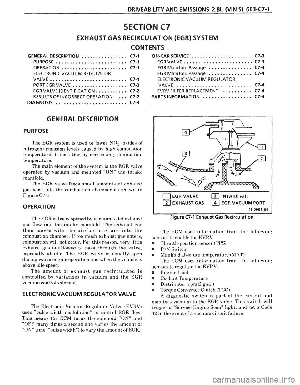
Figure C7-1.
OPERATION
..................... ON-CAR SERVICE C7-3
EGR VALVE
........................ C7-3
EGR Manifold Passage
............... C7-3
EGR Manifold Passage
............... C7-4
ELECTRONIC VACUUM REGULATOR
VALVE
.......................... C7-4
EVRV FILTER REPLACEMENT
.......... C7-4
................. PARTS INFORMATION C7-4
EGR VALVE INTAKE AIR
1 EXHAUST GAS EGR VACUUM PORT I
The EGR valve is opened by vacuum to let exhaust
gas flow into the intake manifold.
l'he exhaust gas
then moves
witb the airlfuel mixture into the
combustion chamber. If too much exhaust gas enters,
combustion will not occur. For this reason, very little
exhaust gas is allowed to pass through the valve,
especially at idle. The
EGR valve is usually open
during warm engine operation and when the vehicle is
above idle speed.
The amount of exhaust gas recirculated is
controlled by variations in vacuum and the EGR
vacuum control solenoid.
ELECTRONIC VACUUM REGULATOR VALVE
The Electronic Vacuum Regulator Valve (EVRV)
uses "pulse width modulation" to control EGK flow.
This
means the ECM turns the solenoid "ON" and
"OFF many times a second and varies the amount of
"ON" time ("pulse width") to vary the amount ot'HGK.
Figure C7-1 Exhaust Gas Recirculation
The i1:CM uses information from the following
sensors to enable the EVRV:
@ Throttle position sensor ('I'PS)
@ Plh' Switch
Manifold
ahsolute temperature (MArI')
The ECM uses information from the following
sensors to regulate the EVRV:
@ Engine 1,oad
Coolant Temperature
@ 1)istributor (rpm Signal)
@ Torque Converter Clutch (TCC)
A diagnostic switch is part of the control and
monitors vacuum to the
EGK. valve. 'I'his switch will
trigger a "Service Engine Soon" light, and set a Code
ai ure. 32 in the event of a vacuum circuit f 'I
Page 811 of 1825
6E3-A-8 5.OL (VIN F) & 5.7L(VIN 8) DRIVEABILITY AND EMISSIONS
DIAGNOSIC CIRCUIXCHECK
The Diagnostic Circuit Checlc is an organized approach to identifying a problem created by an Electronic
Engine Control System malfunction. It
must be the starting point for any driveability complaint diagnosis,
because it directs the Service Technician to the next logical step in diagnosing the complaint.
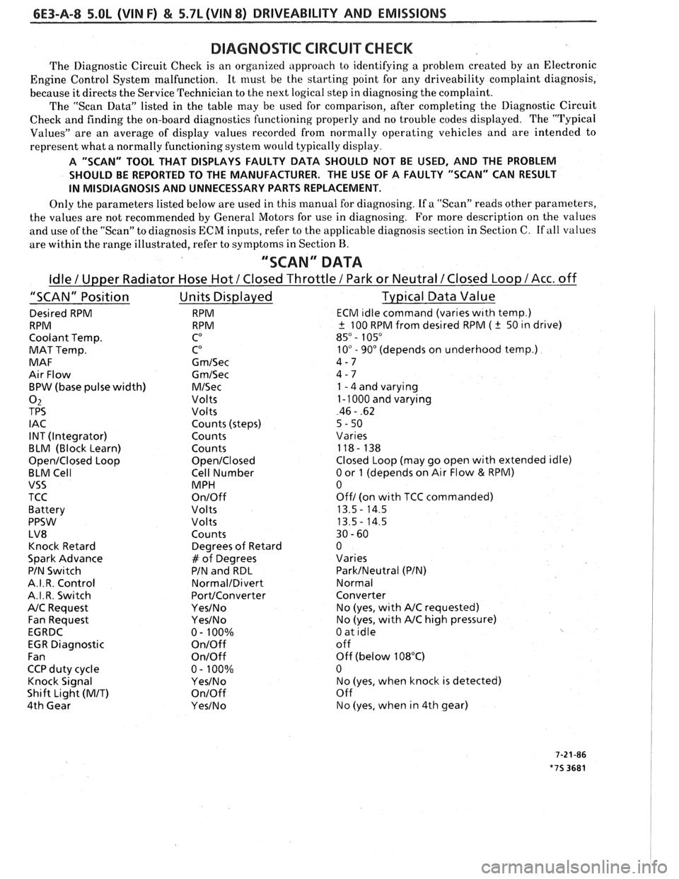
The "Scan Data" listed in the table may be used for comparison, after completing the Diagnostic Circuit
Check and finding the on-board diagnostics functioning properly and no trouble codes displayed. The "Typical
Values" are an average of display values recorded from normally operating vehicles and are intended to
represent what a normally functioning system would typically display.
A "SCAN" TOOL THAT DISPLAYS FAULTY DATA SHOULD NOT BE USED, AND THE PROBLEM
SHOULD BE REPORTED TO THE MANUFACTURER. THE USE OF A FAULTY "SCAN" CAN RESULT
IN MISDIAGNOSIS AND UNNECESSARY PARTS REPLACEMENT.
Only the parameters listed below are used in this manual for diagnosing. If a "Scan" reads other parameters,
the values are not recommended by General Motors for use in diagnosing. For more description on the values
and use of the "Scan" to diagnosis ECM inputs, refer to the applicable diagnosis section in Section C.
If all values
are within the range illustrated, refer to symptoms in Section
B.
"SCAN" DATA
Idle / Upper Radiator Hose Hot / Closed Throttle / Park or Neutral /Closed Loop /Acc. off
"SCAN" Position Units Displayed Typical Data Value
Desired RPM RPM ECM ~dle command (vanes w~th temp.)
RPM RPM
+ 100 RPM from desired RPM ( k 50 ~n drive)
Coolant Temp.
CO 85" - 105"
MAT Temp. CO 10" - 90" (depends on underhood temp.)
MAF G
m/Sec 4-7
Air Flow
Gm/Sec 4 - 7
BPW (base pulse width)
M/Sec 1 - 4 and varying
02 Volts 1 - 1000 and varying
TPS Volts 46 - .62
I AC Counts (steps)
5 - 50
INT (Integrator) Counts
Vanes
BLM (Block Learn) Counts 118- 138
Open/Closed Loop Open/Closed Closed Loop (may go open with extended idle)
BLM Cell Cell Number
0 or 1 (depends on Air Flow & RPM)
VSS MPH 0
TCC
On/Off Off/ (on wlth TCC commanded)
Battery Volts 13.5
- 14.5
PPSW
Volts 13.5- 14.5
LV8 Counts 30
- 60
Knock Retard Degrees
of Retard 0
Spark Advance
# of Degrees Varies
PIN
Swltch PIN and RDL ParkINeutral (PIN)
A.I. R. Control
Normal/Divert Normal
A.I.R. Switch
PortIConverter Converter
NC Request Yes/No No (yes, wlth NC requested)
Fan Request
Yes/No No (yes, with NC high pressure)
EGRDC 0- 100%
0 at idle
EGR Diagnostic
On/Off off
Fan
OnIOff Off (below 108°C)
CCP duty cycle 0
- 100% 0
Knock Signal
YesINo No (yes, when knock is detected)
Shift Light
(MIT) On/Off Off
4th Gear
Yes/No No (yes, when in 4th gear)