1988 OPEL VECTRA seats
[x] Cancel search: seatsPage 12 of 525
Refitting
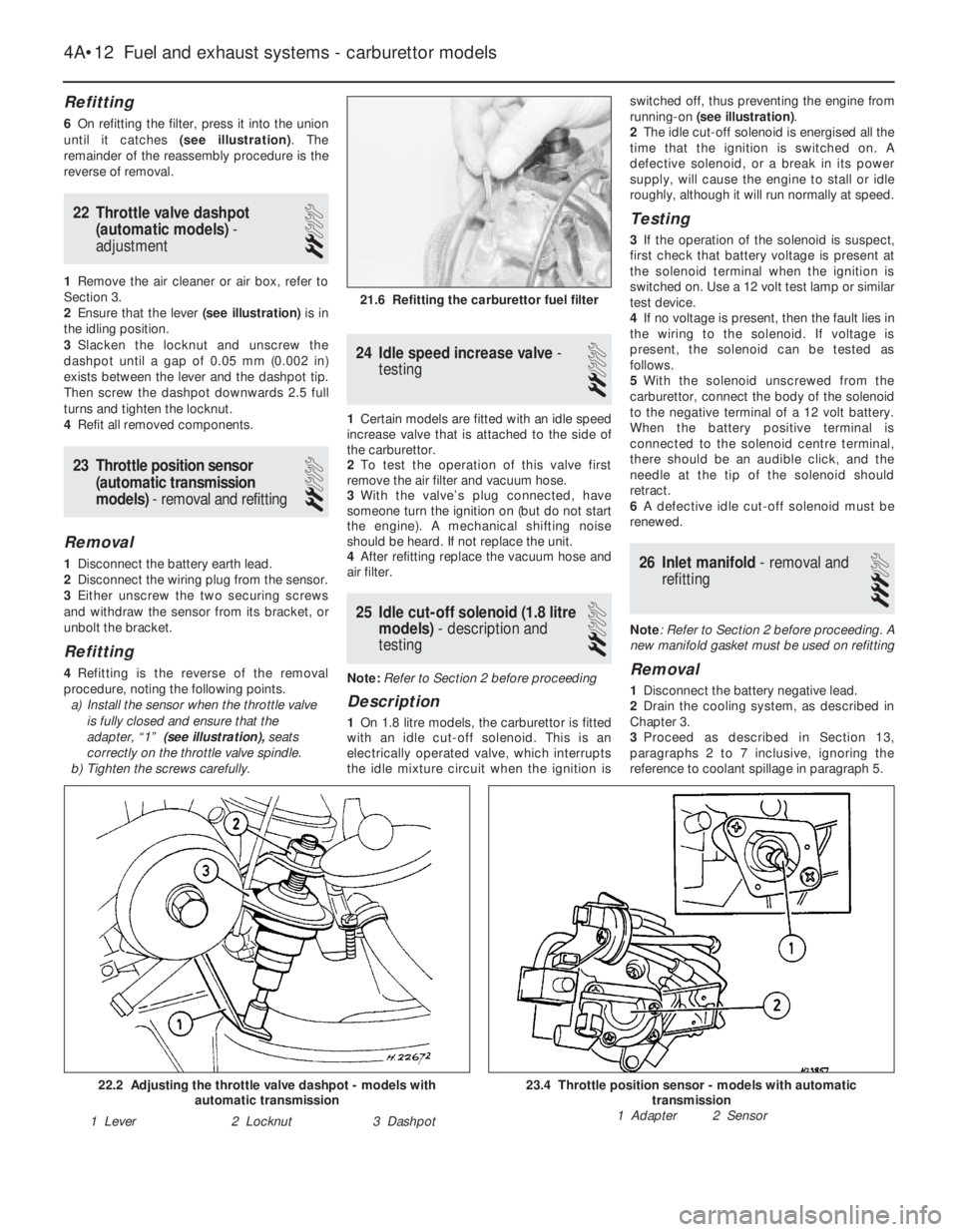
6On refitting the filter, press it into the union
until it catches (see illustration). The
remainder of the reassembly procedure is the
reverse of removal.
22Throttle valve dashpot
(automatic models) -
adjustment
2
1Remove the air cleaner or air box, refer to
Section 3.
2Ensure that the lever (see illustration)is in
the idling position.
3Slacken the locknut and unscrew the
dashpot until a gap of 0.05 mm (0.002 in)
exists between the lever and the dashpot tip.
Then screw the dashpot downwards 2.5 full
turns and tighten the locknut.
4Refit all removed components.
23Throttle position sensor
(automatic transmission
models) - removal and refitting
2
Removal
1Disconnect the battery earth lead.
2Disconnect the wiring plug from the sensor.
3Either unscrew the two securing screws
and withdraw the sensor from its bracket, or
unbolt the bracket.
Refitting
4Refitting is the reverse of the removal
procedure, noting the following points.
a)Install the sensor when the throttle valve
is fully closed and ensure that the
adapter, “1” (see illustration),seats
correctly on the throttle valve spindle.
b)Tighten the screws carefully.
24Idle speed increase valve -
testing
2
1Certain models are fitted with an idle speed
increase valve that is attached to the side of
the carburettor.
2To test the operation of this valve first
remove the air filter and vacuum hose.
3With the valve’s plug connected, have
someone turn the ignition on (but do not start
the engine). A mechanical shifting noise
should be heard. If not replace the unit.
4After refitting replace the vacuum hose and
air filter.
25Idle cut-off solenoid (1.8 litre
models) - description and
testing
2
Note: Refer to Section 2 before proceeding
Description
1On 1.8 litre models, the carburettor is fitted
with an idle cut-off solenoid. This is an
electrically operated valve, which interrupts
the idle mixture circuit when the ignition isswitched off, thus preventing the engine from
running-on (see illustration).
2The idle cut-off solenoid is energised all the
time that the ignition is switched on. A
defective solenoid, or a break in its power
supply, will cause the engine to stall or idle
roughly, although it will run normally at speed.
Testing
3If the operation of the solenoid is suspect,
first check that battery voltage is present at
the solenoid terminal when the ignition is
switched on. Use a 12 volt test lamp or similar
test device.
4If no voltage is present, then the fault lies in
the wiring to the solenoid. If voltage is
present, the solenoid can be tested as
follows.
5With the solenoid unscrewed from the
carburettor, connect the body of the solenoid
to the negative terminal of a 12 volt battery.
When the battery positive terminal is
connected to the solenoid centre terminal,
there should be an audible click, and the
needle at the tip of the solenoid should
retract.
6A defective idle cut-off solenoid must be
renewed.
26Inlet manifold - removal and
refitting
3
Note: Refer to Section 2 before proceeding. A
new manifold gasket must be used on refitting
Removal
1Disconnect the battery negative lead.
2Drain the cooling system, as described in
Chapter 3.
3Proceed as described in Section 13,
paragraphs 2 to 7 inclusive, ignoring the
reference to coolant spillage in paragraph 5.
4A•12Fuel and exhaust systems - carburettor models
21.6 Refitting the carburettor fuel filter
23.4 Throttle position sensor - models with automatic
transmission
1 Adapter 2 Sensor22.2 Adjusting the throttle valve dashpot - models with
automatic transmission
1 Lever2 Locknut3 Dashpot
Page 15 of 525
12
Wiper blades
Type . . . . . . . . . . . . . . . . . . . . . . . . . . . . . . . . . . . . . . . . . . . . . . . . . . . . 19 ins. Champion X-4803
Fuses
Rating:
Red . . . . . . . . . . . . . . . . . . . . . . . . . . . . . . . . . . . . . . . . . . . . . . . . . . . 10 A
Blue . . . . . . . . . . . . . . . . . . . . . . . . . . . . . . . . . . . . . . . . . . . . . . . . . . . 15 A
Yellow . . . . . . . . . . . . . . . . . . . . . . . . . . . . . . . . . . . . . . . . . . . . . . . . . 20 A
Green . . . . . . . . . . . . . . . . . . . . . . . . . . . . . . . . . . . . . . . . . . . . . . . . . 30 A
Torque wrench settingsNm lbf ft
Airbag unit to steering wheel . . . . . . . . . . . . . . . . . . . . . . . . . . . . . . . . . 10 7
Airbag control . . . . . . . . . . . . . . . . . . . . . . . . . . . . . . . . . . . . . . . . . . . . . 10 7
Brackets, passenger airbag . . . . . . . . . . . . . . . . . . . . . . . . . . . . . . . . . . 22 16
Passenger airbag to bracket . . . . . . . . . . . . . . . . . . . . . . . . . . . . . . . . . 8 6
Steering to column . . . . . . . . . . . . . . . . . . . . . . . . . . . . . . . . . . . . . . . . . 25 18
Chapter 12
Body electrical systems
Aerial - removal and refitting . . . . . . . . . . . . . . . . . . . . . . . . . . . . . . .47
Aerial mast, electric - removal and refitting . . . . . . . . . . . . . . . . . . . .48
Airbag - general . . . . . . . . . . . . . . . . . . . . . . . . . . . . . . . . . . . . . . . . .55
Airbag contact unit - removal and refitting . . . . . . . . . . . . . . . . . . . . .58
Airbag control unit - removal and refitting . . . . . . . . . . . . . . . . . . . . .61
Airbag unit, drivers side - removal and refitting . . . . . . . . . . . . . . . . .56
Airbag unit, passengers side - removal and refitting . . . . . . . . . . . . .59
Anti-theft alarm - general . . . . . . . . . . . . . . . . . . . . . . . . . . . . . . . . . .53
Anti-theft alarm system components - removal and refitting . . . . . . .54
Bracket, passenger airbag unit - removal and refitting . . . . . . . . . . .60
Brake lamp switch - removal and refitting . . . . . . . . . . . . . . . . . . . . .12
Central door locking components - removal and refitting . . . . . . . . .46
Check control system components - removal and refitting . . . . . . . .21
Cigarette lighter - removal and refitting . . . . . . . . . . . . . . . . . . . . . . .15
Clock - removal and refitting . . . . . . . . . . . . . . . . . . . . . . . . . . . . . . .16
Courtesy lamp switch - removal and refitting . . . . . . . . . . . . . . . . . . .10
Direction indicator/lighting switch - removal and refitting . . . . . . . . . .5
Electric door mirror switch - removal and refitting . . . . . . . . . . . . . . . .8
Electric window components - removal and refitting . . . . . . . . . . . . .44
Electric window controls - programming . . . . . . . . . . . . . . . . . . . . . .45
Electrical fault-finding - general information . . . . . . . . . . . . . . . . . . . . .2
Exterior lamp bulbs - renewal . . . . . . . . . . . . . . . . . . . . . . . . . . . . . . .34
Facia panel switches - removal and refitting . . . . . . . . . . . . . . . . . . . .7
Front indicator lamp unit - removal and refitting . . . . . . . . . . . . . . . .29
Front foglamp - removal, refitting and adjustment . . . . . . . . . . . . . . .31
Fuses and relays - general . . . . . . . . . . . . . . . . . . . . . . . . . . . . . . . . . .3
General information and precautions . . . . . . . . . . . . . . . . . . . . . . . . . .1
Handbrake “on” warning lamp switch - removal and refitting . . . . . .13
Headlamp aim adjustment motor - removal and refitting . . . . . . . . . .26
Headlamp dim-dip system - general, removal and refitting . . . . . . . .28
Headlamp unit - removal and refitting . . . . . . . . . . . . . . . . . . . . . . . .25
Headlamp washer fluid non-return valve - removal and refitting . . . .43Headlamp wiper motor - removal and refitting . . . . . . . . . . . . . . . . . .40
Headlamps - alignment . . . . . . . . . . . . . . . . . . . . . . . . . . . . . . . . . . .27
Heated front seats - general . . . . . . . . . . . . . . . . . . . . . . . . . . . . . . . .17
Horn(s) - removal and refitting . . . . . . . . . . . . . . . . . . . . . . . . . . . . . .22
Ignition switch and lock cylinder - removal and refitting . . . . . . . . . . .4
Instrument panel - removal and refitting . . . . . . . . . . . . . . . . . . . . . .18
Instrument panel components - removal and refitting . . . . . . . . . . . .19
Interior lamp bulbs - renewal . . . . . . . . . . . . . . . . . . . . . . . . . . . . . . .24
Interior lamps - removal and refitting . . . . . . . . . . . . . . . . . . . . . . . . .23
Luggage compartment lamp switch - removal and refitting . . . . . . .11
Number plate lamp - removal and refitting . . . . . . . . . . . . . . . . . . . . .33
Oil pressure warning lamp switch - removal and refitting . . . . . . . . .14
Radio/cassette player - removal and refitting . . . . . . . . . . . . . . . . . . .50
Rear lamp unit - removal and refitting . . . . . . . . . . . . . . . . . . . . . . . .32
Reversing lamp switch . . . . . . . . . . . . . . . . . . . . . . . . .See Chapter 7A
Side repeater lamp - removal and refitting . . . . . . . . . . . . . . . . . . . . .30
Speakers - removal and refitting . . . . . . . . . . . . . . . . . . . . . . . . . . . .49
Speedometer cable - removal and refitting . . . . . . . . . . . . . . . . . . . .52
Steering wheel (with airbag) - removal and refitting . . . . . . . . . . . . . .57
Sunroof motor - removal and refitting . . . . . . . . . . . . . . . . . . . . . . . .51
Sunroof operating switch - removal and refitting . . . . . . . . . . . . . . . . .9
Tailgate wiper motor - removal and refitting . . . . . . . . . . . . . . . . . . . .39
Trip computer components - removal and refitting . . . . . . . . . . . . . .20
Wash/wipe switch - removal and refitting . . . . . . . . . . . . . . . . . . . . . .6
Washer fluid reservoir - removal and refitting . . . . . . . . . . . . . . . . . . .41
Washer nozzles - removal and refitting . . . . . . . . . . . . . . . . . . . . . . .37
Washer pump - removal and refitting . . . . . . . . . . . . . . . . . . . . . . . . .42
Windscreen wiper motor and linkage - removal and refitting . . . . . . .38
Wiper arms - removal and refitting . . . . . . . . . . . . . . . . . . . . . . . . . . .36
Wiper blades - renewal . . . . . . . . . . . . . . . . . . . . . . . . . . . . . . . . . . . .35
Wiring diagrams - general . . . . . . . . . . . . . . . . . . . . . . . . . . . . . . . . .62
12•1
Specifications Contents
Easy,suitable for
novice with little
experienceFairly easy,suitable
for beginner with
some experienceFairly difficult,
suitable for competent
DIY mechanic
Difficult,suitable for
experienced DIY
mechanicVery difficult,
suitable for expert DIY
or professional
Degrees of difficulty
54321
Page 20 of 525
3To remove the cigarette lighter assembly,
simply pull it from the illumination ring
assembly. If desired, the illumination ring
assembly can be removed, by pulling it from
the housing after depressing the retaining
clips.
Refitting
4Refitting is a reversal of removal.
16Clock - removal and refitting
2
Removal
1Disconnect the battery negative lead.
2Using a thin-bladed screwdriver, carefully
prise the clock from the facia panel.
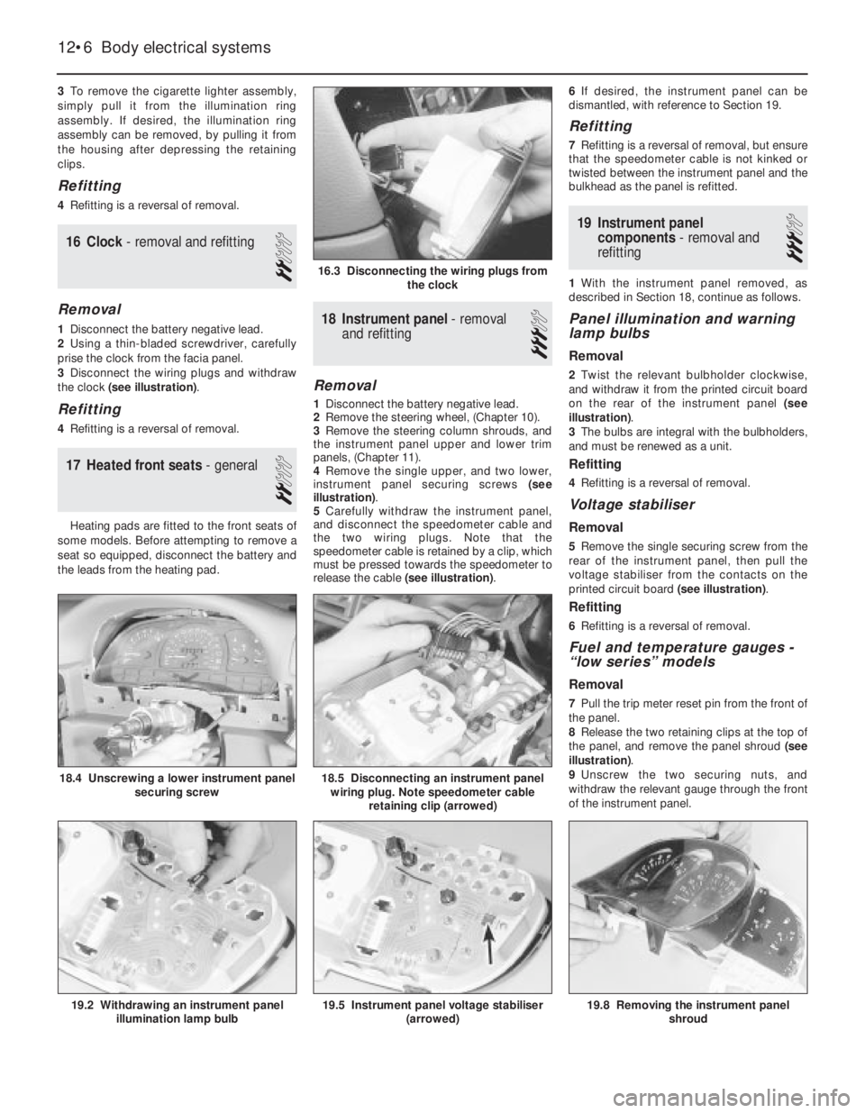
3Disconnect the wiring plugs and withdraw
the clock (see illustration).
Refitting
4Refitting is a reversal of removal.
17Heated front seats - general
2
Heating pads are fitted to the front seats of
some models. Before attempting to remove a
seat so equipped, disconnect the battery and
the leads from the heating pad.
18Instrument panel -removal
and refitting
3
Removal
1Disconnect the battery negative lead.
2Remove the steering wheel, (Chapter 10).
3Remove the steering column shrouds, and
the instrument panel upper and lower trim
panels, (Chapter 11).
4Remove the single upper, and two lower,
instrument panel securing screws (see
illustration).
5Carefully withdraw the instrument panel,
and disconnect the speedometer cable and
the two wiring plugs. Note that the
speedometer cable is retained by a clip, which
must be pressed towards the speedometer to
release the cable (see illustration).6If desired, the instrument panel can be
dismantled, with reference to Section 19.
Refitting
7Refitting is a reversal of removal, but ensure
that the speedometer cable is not kinked or
twisted between the instrument panel and the
bulkhead as the panel is refitted.
19Instrument panel
components - removal and
refitting
3
1With the instrument panel removed, as
described in Section 18, continue as follows.
Panel illumination and warning
lamp bulbs
Removal
2Twist the relevant bulbholder clockwise,
and withdraw it from the printed circuit board
on the rear of the instrument panel (see
illustration).
3The bulbs are integral with the bulbholders,
and must be renewed as a unit.
Refitting
4Refitting is a reversal of removal.
Voltage stabiliser
Removal
5Remove the single securing screw from the
rear of the instrument panel, then pull the
voltage stabiliser from the contacts on the
printed circuit board (see illustration).
Refitting
6Refitting is a reversal of removal.
Fuel and temperature gauges -
“low series” models
Removal
7Pull the trip meter reset pin from the front of
the panel.
8Release the two retaining clips at the top of
the panel, and remove the panel shroud (see
illustration).
9Unscrew the two securing nuts, and
withdraw the relevant gauge through the front
of the instrument panel.
12•6Body electrical systems
16.3 Disconnecting the wiring plugs from
the clock
18.5 Disconnecting an instrument panel
wiring plug. Note speedometer cable
retaining clip (arrowed)
19.8 Removing the instrument panel
shroud19.5 Instrument panel voltage stabiliser
(arrowed)19.2 Withdrawing an instrument panel
illumination lamp bulb
18.4 Unscrewing a lower instrument panel
securing screw
Page 24 of 525
27Headlamps -alignment
2
1Correct alignment of the headlamp beams
is most important, not only to ensure good
vision for the driver, but also to protect other
drivers from being dazzled.
2Accurate alignment should be carried out
using optical beam setting equipment.
3In an emergency, adjustments may be
made by turning the adjustment screws
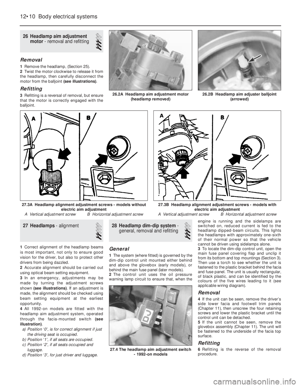
shown (see illustrations). If an adjustment is
made, the alignment should be checked using
beam setting equipment at the earliest
opportunity.
4All 1992-on models are fitted with the
headlamp aim adjustment system, operated
through the facia-mounted switch (see
illustration).
a)Position ‘0’, is for correct alignment if just
the driving seat is occupied.
b)Position ‘1’, if all seats are occupied.
c)Position ‘2’, if all seats occupied and
luggage.
d)Position ‘3’, for just driver and luggage.
28Headlamp dim-dip system -
general, removal and refitting
3
General
1The system (where fitted) is governed by the
dim-dip control unit mounted either behind
and above the glovebox (early models), or
behind the main fuse panel (later models).
2The control unit uses the oil pressure
warning lamp circuit to ensure that, when theengine is running and the sidelamps are
switched on, reduced current is fed to the
headlamp dipped-beam circuits. This lights
the headlamps with approximately one-sixth
of their normal power so that the vehicle
cannot be driven using sidelamps alone.
3To locate the dim-dip control unit, open the
main fuse panel covering flap and unclip it
from its bottom and top mountings (Section 3).
Then use a torch to see whether the unit is
fastened to the plastic bracket behind the facia
and fuse panel. The unit is usually rectangular,
of black plastic, and can be identified by the
colours of the five wires leading to it (see
applicable wiring diagram).
Removal
4If the unit can be seen, remove the driver’s
side lower facia and footwell trim panels
(Chapter 11), then unscrew the four retaining
screws and lower the plastic bracket until the
control unit can be detached.
5If the unit cannot be seen, remove the
glovebox assembly (Chapter 11). The unit will
be fastened to the underside of the facia top
surface.
Refitting
6Refitting is the reverse of the removal
procedure.
26Headlamp aim adjustment
motor - removal and refitting
3
Removal
1Remove the headlamp, (Section 25).
2Twist the motor clockwise to release it from
the headlamp, then carefully disconnect the
motor from the balljoint (see illustrations).
Refitting
3Refitting is a reversal of removal, but ensure
that the motor is correctly engaged with the
balljoint.
12•10Body electrical systems
26.2A Headlamp aim adjustment motor
(headlamp removed)
27.4 The headlamp aim adjustment switch
- 1992-on models
27.3B Headlamp alignment adjustment screws - models with
electric aim adjustment
A Vertical adjustment screw B Horizontal adjustment screw27.3A Headlamp alignment adjustment screws - models without
electric aim adjustment
A Vertical adjustment screw B Horizontal adjustment screw
26.2B Headlamp aim adjuster balljoint
(arrowed)
Page 36 of 525
12•22Body electrical systems
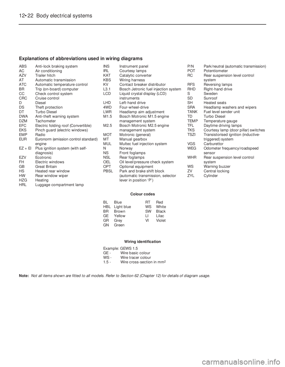
Explanations of abbreviations used in wiring diagrams
ABSAnti-lock braking system
ACAir conditioning
AZVTrailer hitch
ATAutomatic transmission
ATCAutomatic temperature control
BRTrip (on-board) computer
CCCheck control system
CRCCruise control
DDiesel
DSTheft protection
DTTurbo Diesel
DWAAnti-theft warning system
DZMTachometer
EFCElectric folding roof (Convertible)
EKSPinch guard (electric windows)
EMPRadio
EUREuronorm (emission control standard)
engine
EZ + ElPlus ignition system (with self-
diagnosis)
EZVEcotronic
FHElectric windows
GBGreat Britain
HSHeated rear window
HWRear window wiper
HZGHeating
HRLLuggage compartment lampINSInstrument panel
IRLCourtesy lamps
KATCatalytic converter
KBSWiring harness
KVContact breaker distributor
L3.1Bosch Jetronic fuel injection system
LCDLiquid crystal display (LCD)
instruments
LHDLeft-hand drive
4WDFour-wheel-drive
LWRHeadlamp aim adjustment
M1.5Bosch Motronic M1.5 engine
management system
M2.5Bosch Motronic M2.5 engine
management system
MOTMotronic (general)
MTManual gearbox
MULMultec fuel injection system
NNorway
NSFront foglamps
NSLRear foglamps
OELOil level/pressure check system
OPTOptional equipment
PBSLPark and brake shift block
(automatic transmission, selector
lever in position ‘P’)P/NPark/neutral (automatic transmission)
POTPotentiometer
RCRear suspension level control
system
RFSReversing lamps
RHDRight-hand drive
SSweden
SDSunroof
SHHeated seats
SRAHeadlamp washers and wipers
TANKFuel level sender unit
TDTurbo Diesel
TEMPTemperature gauge
TFLDaytime driving lamps
TKSCourtesy lamp (door pillar) switches
TSZITransistorised ignition (inductive-
triggered) system
VGSCarburettor
WEGOdometer frequency/roadspeed
sensor
WHRRear suspension level control
system
WSWarning buzzer
ZVCentral locking
ZYLCylinder
Colour codes
BLBlue
HBLLight blue
BRBrown
GEYellow
GRGrey
GNGreenRTRed
WSWhite
SWBlack
LILilac
VIViolet
Wiring identification
Example: GEWS 1.5
GE -Wire basic colour
WS -Wire tracer colour
1.5 -Wire cross-section in mm
2
Note: Not all items shown are fitted to all models. Refer to Section 62 (Chapter 12) for details of diagram usage.
Page 52 of 525
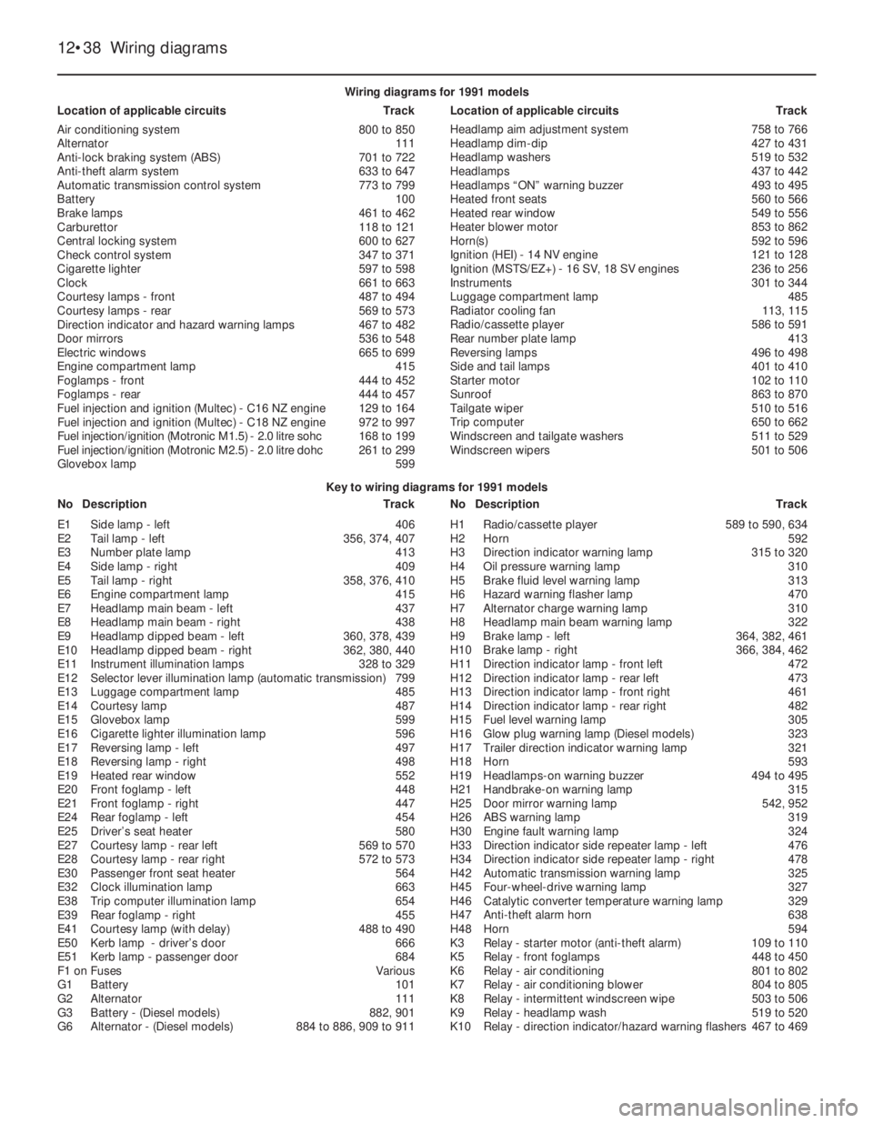
12•38Wiring diagrams
Key to wiring diagrams for 1991 models
NoDescriptionTrackNoDescriptionTrack Wiring diagrams for 1991 models
Location of applicable circuitsTrackLocation of applicable circuitsTrack
Air conditioning system800 to 850
Alternator111
Anti-lock braking system (ABS)701 to 722
Anti-theft alarm system633 to 647
Automatic transmission control system773 to 799
Battery100
Brake lamps461 to 462
Carburettor118 to 121
Central locking system600 to 627
Check control system347 to 371
Cigarette lighter597 to 598
Clock661 to 663
Courtesy lamps - front487 to 494
Courtesy lamps - rear569 to 573
Direction indicator and hazard warning lamps467 to 482
Door mirrors536 to 548
Electric windows665 to 699
Engine compartment lamp415
Foglamps - front444 to 452
Foglamps - rear444 to 457
Fuel injection and ignition (Multec) - C16NZ engine129 to 164
Fuel injection and ignition (Multec) - C18NZ engine972 to 997
Fuel injection/ignition (Motronic M1.5) - 2.0litre sohc 168 to 199
Fuel injection/ignition (Motronic M2.5) - 2.0litre dohc 261 to 299
Glovebox lamp599Headlamp aim adjustment system758 to 766
Headlamp dim-dip427 to 431
Headlamp washers519 to 532
Headlamps437 to 442
Headlamps “ON” warning buzzer493 to 495
Heated front seats560 to 566
Heated rear window549 to 556
Heater blower motor853 to 862
Horn(s)592 to 596
Ignition (HEI) - 14NV engine121 to 128
Ignition (MSTS/EZ+) - 16SV, 18 SV engines236 to 256
Instruments301 to 344
Luggage compartment lamp485
Radiator cooling fan113, 115
Radio/cassette player586 to 591
Rear number plate lamp413
Reversing lamps496 to 498
Side and tail lamps401 to 410
Starter motor102 to 110
Sunroof863 to 870
Tailgate wiper510 to 516
Trip computer650 to 662
Windscreen and tailgate washers511 to 529
Windscreen wipers501 to 506
E1Side lamp - left406
E2Tail lamp - left356, 374, 407
E3Number plate lamp413
E4Side lamp - right409
E5Tail lamp - right358, 376, 410
E6Engine compartment lamp415
E7Headlamp main beam - left437
E8Headlamp main beam - right438
E9Headlamp dipped beam - left360, 378, 439
E10Headlamp dipped beam - right362, 380, 440
E11Instrument illumination lamps328 to 329
E12Selector lever illumination lamp (automatic transmission)799
E13Luggage compartment lamp485
E14Courtesy lamp487
E15Glovebox lamp599
E16Cigarette lighter illumination lamp596
E17Reversing lamp - left497
E18Reversing lamp - right498
E19Heated rear window552
E20Front foglamp - left448
E21Front foglamp - right447
E24Rear foglamp - left454
E25Driver’s seat heater580
E27Courtesy lamp - rear left569 to 570
E28Courtesy lamp - rear right572 to 573
E30Passenger front seat heater564
E32Clock illumination lamp663
E38Trip computer illumination lamp654
E39Rear foglamp - right455
E41Courtesy lamp (with delay)488 to 490
E50Kerb lamp - driver’s door666
E51Kerb lamp - passenger door684
F1 onFusesVarious
G1Battery101
G2Alternator111
G3Battery - (Diesel models)882, 901
G6Alternator - (Diesel models)884 to 886, 909 to 911H1Radio/cassette player589 to 590, 634
H2Horn592
H3Direction indicator warning lamp315 to 320
H4Oil pressure warning lamp310
H5Brake fluid level warning lamp313
H6Hazard warning flasher lamp470
H7Alternator charge warning lamp310
H8Headlamp main beam warning lamp322
H9Brake lamp - left364, 382, 461
H10Brake lamp - right366, 384, 462
H11Direction indicator lamp - front left472
H12Direction indicator lamp - rear left473
H13Direction indicator lamp - front right461
H14Direction indicator lamp - rear right482
H15Fuel level warning lamp305
H16Glow plug warning lamp (Diesel models)323
H17Trailer direction indicator warning lamp321
H18Horn593
H19Headlamps-on warning buzzer494 to 495
H21Handbrake-on warning lamp315
H25Door mirror warning lamp542, 952
H26ABS warning lamp319
H30Engine fault warning lamp324
H33Direction indicator side repeater lamp - left476
H34Direction indicator side repeater lamp - right478
H42Automatic transmission warning lamp325
H45Four-wheel-drive warning lamp327
H46Catalytic converter temperature warning lamp329
H47Anti-theft alarm horn638
H48Horn594
K3Relay - starter motor (anti-theft alarm)109 to 110
K5Relay - front foglamps448 to 450
K6Relay - air conditioning801 to 802
K7Relay - air conditioning blower804 to 805
K8Relay - intermittent windscreen wipe503 to 506
K9Relay - headlamp wash519 to 520
K10Relay - direction indicator/hazard warning flashers467 to 469
Page 104 of 525
11
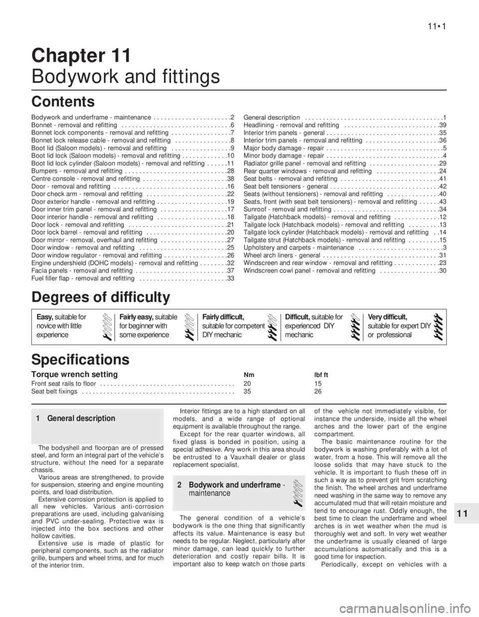
Torque wrench settingNm lbf ft
Front seat rails to floor . . . . . . . . . . . . . . . . . . . . . . . . . . . . . . . . . . . . . . 20 15
Seat belt fixings . . . . . . . . . . . . . . . . . . . . . . . . . . . . . . . . . . . . . . . . . . . 35 26
1 General description
The bodyshell and floorpan are of pressed
steel, and form an integral part of the vehicle’s
structure, without the need for a separate
chassis.
Various areas are strengthened, to provide
for suspension, steering and engine mounting
points, and load distribution.
Extensive corrosion protection is applied to
all new vehicles. Various anti-corrosion
preparations are used, including galvanising
and PVC under-sealing. Protective wax is
injected into the box sections and other
hollow cavities.
Extensive use is made of plastic for
peripheral components, such as the radiator
grille, bumpers and wheel trims, and for much
of the interior trim.Interior fittings are to a high standard on all
models, and a wide range of optional
equipment is available throughout the range.
Except for the rear quarter windows, all
fixed glass is bonded in position, using a
special adhesive. Any work in this area should
be entrusted to a Vauxhall dealer or glass
replacement specialist.
2 Bodywork and underframe -
maintenance
1
The general condition of a vehicle’s
bodywork is the one thing that significantly
affects its value. Maintenance is easy but
needs to be regular. Neglect, particularly after
minor damage, can lead quickly to further
deterioration and costly repair bills. It is
important also to keep watch on those partsof the vehicle not immediately visible, for
instance the underside, inside all the wheel
arches and the lower part of the engine
compartment.
The basic maintenance routine for the
bodywork is washing preferably with a lot of
water, from a hose. This will remove all the
loose solids that may have stuck to the
vehicle. It is important to flush these off in
such a way as to prevent grit from scratching
the finish. The wheel arches and underframe
need washing in the same way to remove any
accumulated mud that will retain moisture and
tend to encourage rust. Oddly enough, the
best time to clean the underframe and wheel
arches is in wet weather when the mud is
thoroughly wet and soft. In very wet weather
the underframe is usually cleaned of large
accumulations automatically and this is a
good time for inspection.
Periodically, except on vehicles with a
Chapter 11
Bodywork and fittings
Bodywork and underframe - maintenance . . . . . . . . . . . . . . . . . . . . . .2
Bonnet - removal and refitting . . . . . . . . . . . . . . . . . . . . . . . . . . . . . . .6
Bonnet lock components - removal and refitting . . . . . . . . . . . . . . . . .7
Bonnet lock release cable - removal and refitting . . . . . . . . . . . . . . . .8
Boot lid (Saloon models) - removal and refitting . . . . . . . . . . . . . . . . .9
Boot lid lock (Saloon models) - removal and refitting . . . . . . . . . . . . .10
Boot lid lock cylinder (Saloon models) - removal and refitting . . . . . .11
Bumpers - removal and refitting . . . . . . . . . . . . . . . . . . . . . . . . . . . . .28
Centre console - removal and refitting . . . . . . . . . . . . . . . . . . . . . . . .38
Door - removal and refitting . . . . . . . . . . . . . . . . . . . . . . . . . . . . . . . .16
Door check arm - removal and refitting . . . . . . . . . . . . . . . . . . . . . . .22
Door exterior handle - removal and refitting . . . . . . . . . . . . . . . . . . . .19
Door inner trim panel - removal and refitting . . . . . . . . . . . . . . . . . . .17
Door interior handle - removal and refitting . . . . . . . . . . . . . . . . . . . .18
Door lock - removal and refitting . . . . . . . . . . . . . . . . . . . . . . . . . . . .21
Door lock barrel - removal and refitting . . . . . . . . . . . . . . . . . . . . . . .20
Door mirror - removal, overhaul and refitting . . . . . . . . . . . . . . . . . . .27
Door window - removal and refitting . . . . . . . . . . . . . . . . . . . . . . . . .25
Door window regulator - removal and refitting . . . . . . . . . . . . . . . . . .26
Engine undershield (DOHC models) - removal and refitting . . . . . . . .32
Facia panels - removal and refitting . . . . . . . . . . . . . . . . . . . . . . . . . .37
Fuel filler flap - removal and refitting . . . . . . . . . . . . . . . . . . . . . . . . .33General description . . . . . . . . . . . . . . . . . . . . . . . . . . . . . . . . . . . . . . .1
Headlining - removal and refitting . . . . . . . . . . . . . . . . . . . . . . . . . . .39
Interior trim panels - general . . . . . . . . . . . . . . . . . . . . . . . . . . . . . . . .35
Interior trim panels - removal and refitting . . . . . . . . . . . . . . . . . . . . .36
Major body damage - repair . . . . . . . . . . . . . . . . . . . . . . . . . . . . . . . . .5
Minor body damage - repair . . . . . . . . . . . . . . . . . . . . . . . . . . . . . . . . .4
Radiator grille panel - removal and refitting . . . . . . . . . . . . . . . . . . . .29
Rear quarter windows - removal and refitting . . . . . . . . . . . . . . . . . .24
Seat belts - removal and refitting . . . . . . . . . . . . . . . . . . . . . . . . . . . .41
Seat belt tensioners - general . . . . . . . . . . . . . . . . . . . . . . . . . . . . . . .42
Seats (without tensioners) - removal and refitting . . . . . . . . . . . . . . .40
Seats, front (with seat belt tensioners) - removal and refitting . . . . . .43
Sunroof - removal and refitting . . . . . . . . . . . . . . . . . . . . . . . . . . . . . .34
Tailgate (Hatchback models) - removal and refitting . . . . . . . . . . . . .12
Tailgate lock (Hatchback models) - removal and refitting . . . . . . . . .13
Tailgate lock cylinder (Hatchback models) - removal and refitting . .14
Tailgate strut (Hatchback models) - removal and refitting . . . . . . . . .15
Upholstery and carpets - maintenance . . . . . . . . . . . . . . . . . . . . . . . .3
Wheel arch liners - general . . . . . . . . . . . . . . . . . . . . . . . . . . . . . . . . .31
Windscreen and rear window - removal and refitting . . . . . . . . . . . . .23
Windscreen cowl panel - removal and refitting . . . . . . . . . . . . . . . . .30
11•1
Specifications Contents
Easy,suitable for
novice with little
experienceFairly easy,suitable
for beginner with
some experienceFairly difficult,
suitable for competent
DIY mechanic
Difficult,suitable for
experienced DIY
mechanicVery difficult,
suitable for expert DIY
or professional
Degrees of difficulty
54321
Page 105 of 525
wax-based underbody protective coating, it is
a good idea to have the whole of the
underframe of the vehicle steam cleaned,
engine compartment included, so that a
thorough inspection can be carried out to see
what minor repairs and renovations are
necessary. Steam cleaning is available at
many garages and is necessary for removal of
the accumulation of oily grime that sometimes
is allowed to become thick in certain areas.
The dirt can then be simply hosed off. Note
that these methods should not be used on
vehicles with wax-based underbody
protective coating or the coating will be
removed. Such vehicles should be inspected
annually, preferably just before winter, when
the underbody should be washed down and
any damage to the wax coating repaired.
Ideally, a completely fresh coat should be
applied. It would also be worth considering
the use of such wax-based protection for
injection into door panels, sills, box sections,
etc., as an additional safeguard against rust
damage where such protection is not
provided by the vehicle manufacturer.
After washing paintwork, wipe off with a
chamois leather to give an unspotted clear
finish. A coat of clear protective wax polish,
will give added protection against chemical
pollutants in the air. If the paintwork sheen
has dulled or oxidised, use a cleaner/polisher
combination to restore the brilliance of the
shine. This requires a little effort, but such
dulling is usually caused because regular
washing has been neglected. Care needs to
be taken with metallic paintwork, as special
non-abrasive cleaner/polisher is required to
avoid damage to the finish.
Always check that the door and ventilator
opening drain holes and pipes are completely
clear so that water can be drained out. Bright
work should be treated in the same way as
paint work. Windscreens and windows can be
kept clear of the smeary film that often
appears, by using a glass cleaner. Never use
any form of wax or other body or chromium
polish on glass.
3Upholstery and carpets -
maintenance
1
Mats and carpets should be brushed or
vacuum cleaned regularly to keep them free of
grit. If they are badly stained remove them
from the vehicle for scrubbing or sponging
and make quite sure they are dry before
refitting. Seats and interior trim panels can be
kept clean by wiping with a damp cloth. If they
do become stained (which can be more
apparent on light coloured upholstery) use a
little liquid detergent and a soft nail brush to
scour the grime out of the grain of the
material. Do not forget to keep the headlining
clean in the same way as the upholstery.
When using liquid cleaners inside the vehicle
do not over-wet the surfaces being cleaned.Excessive damp could get into the seams and
padded interior causing stains, offensive
odours or even rot. If the inside of the vehicle
gets wet accidentally it is worthwhile taking
some trouble to dry it out properly, particularly
where carpets are involved. Do not leave oil or
electric heaters inside the vehicle for this
purpose.
4Minor body damage - repair
3
Repairs of minor scratches in
bodywork
If the scratch is very superficial, and does
not penetrate to the metal of the bodywork,
repair is very simple. Lightly rub the area of
the scratch with a paintwork renovator, to
remove loose paint from the scratch and to
clear the surrounding bodywork of wax polish.
Rinse the area with clean water.
Apply touch-up paint to the scratch using a
fine paint brush; continue to apply fine layers
of paint until the surface of the paint in the
scratch is level with the surrounding
paintwork. Allow the new paint at least two
weeks to harden: then blend it into the
surrounding paintwork by rubbing the scratch
area with a paintwork renovator or a very fine
cutting paste and apply wax polish.
Where the scratch has penetrated right
through to the metal of the bodywork, causing
the metal to rust, a different repair technique
is required. Remove any loose rust from the
bottom of the scratch with a penknife, then
apply rust inhibiting paint, to prevent the
formation of rust in the future. Using a rubber
or nylon applicator fill the scratch with
bodystopper paste. If required, this paste can
be mixed with cellulose thinners to provide a
very thin paste that is ideal for filling narrow
scratches. Before the stopper-paste in the
scratch hardens, wrap a piece of smooth
cotton rag around the top of a finger. Dip the
finger in cellulose thinners and then quickly
sweep it across the surface of the
stopper-paste in the scratch; this will ensure
that the surface of the stopper-paste is
slightly hollowed. The scratch can now be
painted over as described earlier in this
Section.
Repair of dents in bodywork
When deep denting of the vehicle’s
bodywork has taken place, the first task is to
pull the dent out, until the affected bodywork
almost attains its original shape. There is little
point in trying to restore the original shape
completely, as the metal in the damaged area
will have stretched on impact and cannot be
reshaped fully to its original contour. It is
better to bring the level of the dent up to a
point that is about 8 in (3 mm) below the level
of the surrounding bodywork. In cases where
the dent is very shallow anyway, it is not worthtrying to pull it out at all. If the underside of the
dent is accessible, it can be hammered out
gently from behind, using a mallet with a
wooden or plastic head. Whilst doing this,
hold a block of wood firmly against the
outside of the panel to absorb the impact
from the hammer blows and thus prevent a
large area of the bodywork from being
“belled-out”.
Should the dent be in a section of the
bodywork that has a double skin or some
other factor making it inaccessible from
behind, a different technique is called for. Drill
several small holes through the metal inside
the area particularly in the deeper section.
Then screw long self-tapping screws into the
holes just sufficiently for them to gain a good
purchase in the metal. Now the dent can be
pulled out by pulling on the protruding heads
of the screws with a pair of pliers.
The next stage of the repair is the removal
of the paint from the damaged area, and from
an inch or so of the surrounding “sound”
bodywork. This is accomplished most easily
by using a wire brush or abrasive pad on a
power drill, although it can be done just as
effectively by hand using sheets of abrasive
paper. To complete the preparation for filling,
score the surface of the bare metal with a
screwdriver or the tang of a file, or
alternatively, drill small holes in the affected
area. This will provide a good “key” for the
filler paste.
To complete the repair see the Section on
filling and re-spraying.
Repair of rust holes or gashes in
bodywork
Remove all paint from the affected area and
from an inch or so of the surrounding “sound”
bodywork, using an abrasive pad or a wire
brush on a power drill. If these are not
available a few sheets of abrasive paper will
do the job just as effectively. With the paint
removed you will be able to gauge the severity
of the corrosion and therefore decide whether
to renew the whole panel (if this is possible) or
to repair the affected area. New body panels
are not as expensive as most people think
and it is often quicker and more satisfactory
to fit a new panel than to attempt to repair
large areas of corrosion.
Remove all fittings from the affected area
except those which will act as a guide to the
original shape of the damaged bodywork (e.g.
headlamp shells, etc.). Then, using tin snips or
a hacksaw blade, remove all loose metal and
any other metal badly affected by corrosion.
Hammer the edges of the hole inwards to
create a slight depression for the filler paste.
Wire brush the affected area to remove the
powdery rust from the surface of the
remaining metal. Paint the affected area with
rust inhibiting paint. If the back of the rusted
area is accessible treat this also.
Before filling can take place it will be
necessary to block the hole in some way. This
can be achieved by using aluminium or plastic
mesh, or aluminium tape.
11•2Bodywork and fittings