1988 OPEL VECTRA seats
[x] Cancel search: seatsPage 123 of 525
Refitting
10Refitting is a reversal of removal, but
where applicable, refit the sunroof crank drive,
as described in Section 34.
40Seats (without tensioners) -
removal and refitting
3
Front seats
Removal
1Remove the single securing screw from the
front edge of the outer seat rail trim, then
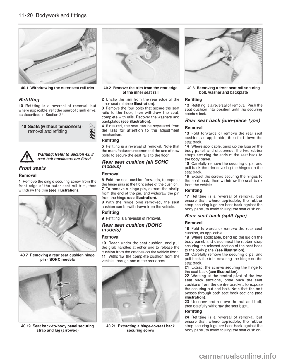
withdraw the trim (see illustration).2Unclip the trim from the rear edge of the
inner seat rail (see illustration).
3Remove the four bolts that secure the seat
rails to the floor, then withdraw the seat,
complete with rails. Recover the washers and
backplates (see illustration).
4If desired, the seat can be separated from
the rails for attention to the adjustment
mechanism.
Refitting
5Refitting is a reversal of removal. Note that
the manufacturers recommend the use of new
bolts to secure the seat rails to the floor.
Rear seat cushion (all SOHC
models)
Removal
6Fold the seat cushion forwards, to expose
the hinge pins at the front edge of the cushion.
7To remove a hinge pin, extract the circlip
from the end of the pin, and withdraw the pin
from the hinge (see illustration).
8With the hinge pins removed, the seat
cushion can be withdrawn from the vehicle.
Refitting
9Refitting is a reversal of removal.
Rear seat cushion (DOHC
models)
Removal
10Reach under the seat cushion, and pull
the grab handles at either end to release the
cushion from the catches on the vehicle floor.
11Withdraw the complete cushion from the
vehicle, through one of the rear doors.
Refitting
12Refitting is a reversal of removal. Push the
seat cushion into position until the securing
catches lock.
Rear seat back (one-piece type)
Removal
13Fold forwards or remove the rear seat
cushion, as applicable, then fold down the
seat back.
14Where applicable, bend up the lugs on the
body panel, and disconnect the two rubber
straps securing the ends of the seat back to
the body panel.
15Carefully remove the securing clips, and
pull back the trim covering the hinges on the
seat back.
16Extract the screws securing the hinges to
the seat back, then withdraw the seat back
from the vehicle.
Refitting
17Refitting is a reversal of removal, but
ensure that, where applicable, the rubber
strap securing lugs are bent back against the
body panel, to avoid fouling the seat cushion.
Rear seat back (split type)
Removal
18Fold forwards or remove the rear seat
cushion, as applicable.
19Where applicable, bend up the lug on the
body panel, and disconnect the rubber strap
securing the relevant section of the seat back
to the body panel (see illustration).
20Carefully remove the securing clips, and
pull back the trim covering the hinge on the
seat back.
21Extract the screws securing the hinge to
the seat back (see illustration).
22Working at the central pivot of the two
seat back sections, prise back the seat
cushions from the centre bracket, to expose
the securing nut and bolt. Note that the bolt
passes through both seat back sections (see
illustration).
23Unscrew and remove the nut and bolt,
then carefully withdraw the seat back.
Refitting
24Refitting is a reversal of removal, but
ensure that, where applicable, the rubber
strap securing lugs are bent back against the
body panel, to avoid fouling the seat cushion.
11•20Bodywork and fittings
40.1 Withdrawing the outer seat rail trim40.3 Removing a front seat rail securing
bolt, washer and backplate
40.7 Removing a rear seat cushion hinge
pin - SOHC models
40.21 Extracting a hinge-to-seat back
securing screw40.19 Seat back-to-body panel securing
strap and lug (arrowed)
40.2 Remove the trim from the rear edge
of the inner seat rail
Warning: Refer to Section 43, if
seat belt tensioners are fitted.
Page 125 of 525
3The tensioner assembly, fitted to the
underside of the front seat, is maintenance
free and, once triggered, must be replaced as
a complete unit.
4Due to the specialist safety related nature
of the seat belt tensioner system, replacement
must be entrusted to a suitably equipped
Vauxhall dealer.
43Front seats (with seat belt
tensioners) -removal and
refitting
3
Removal
1Remove the single securing screw from the
front edge of the outer seat rail trim, release
the rear retaining lug and remove the trim
rearwards.
2Unclip the trim from the rear edge of the
inner seat rail.3Locate the plastic safety fork for the seat
belt tensioner, which is usually taped to the
outside of the tensioner spring cylinder.
4Insert the fork into the aperture provided at
the rear of the spring cylinder, ensuring that
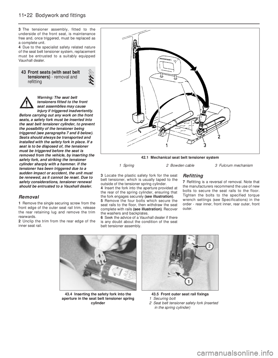
the fork engages securely (see illustration).
5Remove the four bolts which secure the
seat rails to the floor, then withdraw the seat
complete with rails (see illustration). Recover
the washers and backplates.
6Seek the advice of a Vauxhall dealer if there
is any doubt about the condition of the seat
belt tensioner assembly.
Refitting
7Refitting is a reversal of removal. Note that
the manufacturers recommend the use of new
bolts to secure the seat rails to the floor.
Tighten the bolts to the specified torque
wrench settings (see Specifications) in the
order - rear inner, front inner, rear outer, front
outer.
11•22Bodywork and fittings
42.1 Mechanical seat belt tensioner system
1 Spring2 Bowden cable3 Fulcrum mechanism
43.5 Front outer seat rail fixings
1 Securing bolt
2 Seat belt tensioner safety fork (inserted
in the spring cylinder)43.4 Inserting the safety fork into the
aperture in the seat belt tensioner spring
cylinder
Warning: The seat belt
tensioners fitted to the front
seat assemblies may cause
injury if triggered inadvertently.
Before carrying out any work on the front
seats, a safety fork must be inserted into
the seat belt tensioner cylinder, to prevent
the possibility of the tensioner being
triggered (see paragraphs 7 and 8 below).
Seats should always be transported and
installed with the safety fork in place. If a
seat is to be disposed of, the tensioner
must be triggered before the seat is
removed from the vehicle, by inserting the
safety fork, and striking the tensioner
cylinder sharply with a hammer. If the
tensioner has been triggered due to a
sudden impact or accident, the unit must
be renewed, as it cannot be reset. Due to
safety considerations, tensioner renewal
should be entrusted to a Vauxhall dealer.
Page 144 of 525
14Front brake disc shield -
removal and refitting
3
Removal
1Where applicable, remove the wheel trim,
then loosen the relevant front roadwheel bolts
and apply the handbrake. Jack up the front of
the vehicle, and support on axle stands (see
“Jacking and Vehicle Support”) positioned
under the body side members. Remove the
roadwheel.
2Remove the brake disc, as described in
Section 10.
3Using a screwdriver inserted through the
holes in the hub flange, extract the three
screws securing the disc shield to the hub
carrier.
4Using plate shears or an alternative tool, cut
a section of metal from the rear edge of the
shield to enable the shield to be withdrawn
over the hub, then remove the shield (see
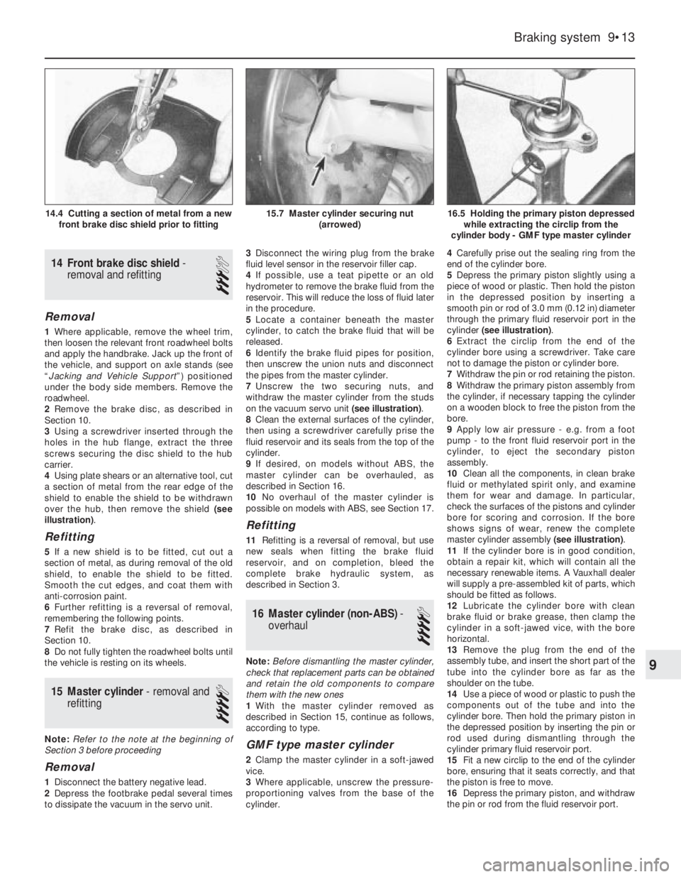
illustration).
Refitting
5If a new shield is to be fitted, cut out a
section of metal, as during removal of the old
shield, to enable the shield to be fitted.
Smooth the cut edges, and coat them with
anti-corrosion paint.
6Further refitting is a reversal of removal,
remembering the following points.
7Refit the brake disc, as described in
Section 10.
8Do not fully tighten the roadwheel bolts until
the vehicle is resting on its wheels.
15Master cylinder - removal and
refitting
4
Note: Refer to the note at the beginning of
Section 3 before proceeding
Removal
1Disconnect the battery negative lead.
2Depress the footbrake pedal several times
to dissipate the vacuum in the servo unit.3Disconnect the wiring plug from the brake
fluid level sensor in the reservoir filler cap.
4If possible, use a teat pipette or an old
hydrometer to remove the brake fluid from the
reservoir. This will reduce the loss of fluid later
in the procedure.
5Locate a container beneath the master
cylinder, to catch the brake fluid that will be
released.
6Identify the brake fluid pipes for position,
then unscrew the union nuts and disconnect
the pipes from the master cylinder.
7Unscrew the two securing nuts, and
withdraw the master cylinder from the studs
on the vacuum servo unit (see illustration).
8Clean the external surfaces of the cylinder,
then using a screwdriver carefully prise the
fluid reservoir and its seals from the top of the
cylinder.
9If desired, on models without ABS, the
master cylinder can be overhauled, as
described in Section 16.
10No overhaul of the master cylinder is
possible on models with ABS, see Section 17.
Refitting
11Refitting is a reversal of removal, but use
new seals when fitting the brake fluid
reservoir, and on completion, bleed the
complete brake hydraulic system, as
described in Section 3.
16Master cylinder (non-ABS) -
overhaul
4
Note: Before dismantling the master cylinder,
check that replacement parts can be obtained
and retain the old components to compare
them with the new ones
1With the master cylinder removed as
described in Section 15, continue as follows,
according to type.
GMF type master cylinder
2Clamp the master cylinder in a soft-jawed
vice.
3Where applicable, unscrew the pressure-
proportioning valves from the base of the
cylinder.4Carefully prise out the sealing ring from the
end of the cylinder bore.
5Depress the primary piston slightly using a
piece of wood or plastic. Then hold the piston
in the depressed position by inserting a
smooth pin or rod of 3.0 mm (0.12 in) diameter
through the primary fluid reservoir port in the
cylinder (see illustration).
6Extract the circlip from the end of the
cylinder bore using a screwdriver. Take care
not to damage the piston or cylinder bore.
7Withdraw the pin or rod retaining the piston.
8Withdraw the primary piston assembly from
the cylinder, if necessary tapping the cylinder
on a wooden block to free the piston from the
bore.
9Apply low air pressure - e.g. from a foot
pump - to the front fluid reservoir port in the
cylinder, to eject the secondary piston
assembly.
10Clean all the components, in clean brake
fluid or methylated spirit only, and examine
them for wear and damage. In particular,
check the surfaces of the pistons and cylinder
bore for scoring and corrosion. If the bore
shows signs of wear, renew the complete
master cylinder assembly (see illustration).
11If the cylinder bore is in good condition,
obtain a repair kit, which will contain all the
necessary renewable items. A Vauxhall dealer
will supply a pre-assembled kit of parts, which
should be fitted as follows.
12Lubricate the cylinder bore with clean
brake fluid or brake grease, then clamp the
cylinder in a soft-jawed vice, with the bore
horizontal.
13Remove the plug from the end of the
assembly tube, and insert the short part of the
tube into the cylinder bore as far as the
shoulder on the tube.
14Use a piece of wood or plastic to push the
components out of the tube and into the
cylinder bore. Then hold the primary piston in
the depressed position by inserting the pin or
rod used during dismantling through the
cylinder primary fluid reservoir port.
15Fit a new circlip to the end of the cylinder
bore, ensuring that it seats correctly, and that
the piston is free to move.
16Depress the primary piston, and withdraw
the pin or rod from the fluid reservoir port.
Braking system 9•13
16.5 Holding the primary piston depressed
while extracting the circlip from the
cylinder body - GMF type master cylinder15.7 Master cylinder securing nut
(arrowed)14.4 Cutting a section of metal from a new
front brake disc shield prior to fitting
9
Page 169 of 525
b)Check the throttle cable operation and
adjustment (see above).
c)When reconnecting the vacuum hoses
and pipes, ensure that they are connected
to the front unions as shown in the
accompanying photograph.
d)As no fuel vapour trap is fitted, it is
essential that the manifold absolute
pressure sensor vacuum hose is routed
so that it falls steadily from the sensor to
the throttle body. This precaution will
prevent any fuel droplets being trapped in
the sensor or hose and allowing them to
drain into the inlet port.
e)Ensure that the fuel hoses are correctly
reconnected; the feed hose is on the
injector end of the throttle body.
f)Switch on the ignition and check for signs
of fuel leaks from all disturbed unions; if
any signs of leakage are detected, the
problem must be rectified before the
engine is started.
33Idle air control stepper
motor - removal and refitting
3
Removal
1Remove the air box (see Section 5).
2Disconnect the battery earth lead.3Disconnect the wiring plug from the stepper
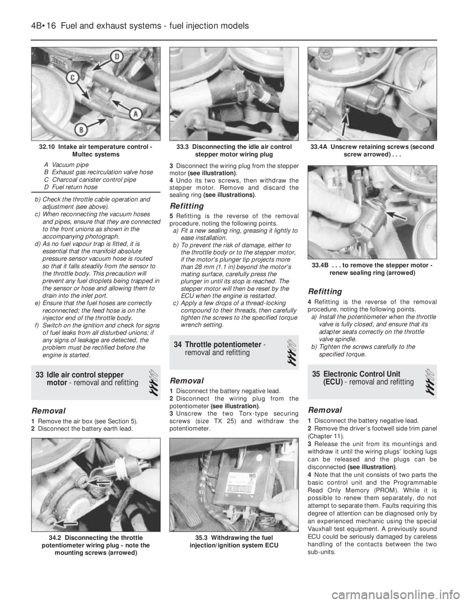
motor (see illustration).
4Undo its two screws, then withdraw the
stepper motor. Remove and discard the
sealing ring (see illustrations).
Refitting
5Refitting is the reverse of the removal
procedure, noting the following points.
a)Fit a new sealing ring, greasing it lightly to
ease installation.
b)To prevent the risk of damage, either to
the throttle body or to the stepper motor,
if the motor’s plunger tip projects more
than 28 mm (1.1 in) beyond the motor’s
mating surface, carefully press the
plunger in until its stop is reached. The
stepper motor will then be reset by the
ECU when the engine is restarted.
c)Apply a few drops of a thread-locking
compound to their threads, then carefully
tighten the screws to the specified torque
wrench setting.
34Throttle potentiometer -
removal and refitting
3
Removal
1Disconnect the battery negative lead.
2Disconnect the wiring plug from the
potentiometer (see illustration).
3Unscrew the two Torx-type securing
screws (size TX 25) and withdraw the
potentiometer.
Refitting
4Refitting is the reverse of the removal
procedure, noting the following points.
a)Install the potentiometer when the throttle
valve is fully closed, and ensure that its
adapter seats correctly on the throttle
valve spindle.
b)Tighten the screws carefully to the
specified torque.
35Electronic Control Unit
(ECU) - removal and refitting
3
Removal
1Disconnect the battery negative lead.
2Remove the driver’s footwell side trim panel
(Chapter 11).
3Release the unit from its mountings and
withdraw it until the wiring plugs’ locking lugs
can be released and the plugs can be
disconnected (see illustration).
4Note that the unit consists of two parts the
basic control unit and the Programmable
Read Only Memory (PROM). While it is
possible to renew them separately, do not
attempt to separate them. Faults requiring this
degree of attention can be diagnosed only by
an experienced mechanic using the special
Vauxhall test equipment. A previously sound
ECU could be seriously damaged by careless
handling of the contacts between the two
sub-units.
4B•16Fuel and exhaust systems - fuel injection models
32.10 Intake air temperature control -
Multec systems
A Vacuum pipe
B Exhaust gas recirculation valve hose
C Charcoal canister control pipe
D Fuel return hose
33.4A Unscrew retaining screws (second
screw arrowed) . . .
35.3 Withdrawing the fuel
injection/ignition system ECU34.2 Disconnecting the throttle
potentiometer wiring plug - note the
mounting screws (arrowed)
33.4B . . . to remove the stepper motor -
renew sealing ring (arrowed)
33.3 Disconnecting the idle air control
stepper motor wiring plug
Page 221 of 525
23Cylinder head - inspection
and renovation
4
Note: Refer to a dealer for advice before
attempting to carry out valve grinding or valve
seat reciting operations, as these operations
may not be possible for the DIY mechanic.
This is due to the fitment of hardened valve
seats for use with unleaded petrol
Inspection
1Remember that the cylinder head is of light
alloy construction and is easily damaged, use
a blunt scraper or rotary wire brush to clean all
traces of carbon deposits from the
combustion spaces and the ports. The valve
stems and valve guides should also be freed
from any carbon deposits. Wash the
combustion spaces and ports down with
paraffin and scrape the cylinder head surface
free of any foreign matter with the side of a
steel rule, or a similar article.
2If the engine is installed in the car, clean the
pistons and the top of the cylinder bores. If
the pistons are still in the block, it is essential
that great care is taken to ensure that no
carbon gets into the cylinder bores. This could
scratch the cylinder walls or cause damage to
the pistons and rings. To ensure this does not
happen, first turn the crankshaft so that two of
the pistons are at the top of their bores. Insert
rag into the other two bores or seal them off
with paper and masking tape. The waterways
should also be covered with small pieces of
masking tape, to prevent particles of carbon
entering the cooling system and damaging the
coolant pump.
3Press a little grease into the gap between
the cylinder walls and the two pistons that are
to be worked on. With a blunt scraper,
carefully scrape away the carbon from the
piston crown, taking great care not to scratch
the aluminium. Also scrape away the carbon
from the surrounding lip of the cylinder wall.
When all carbon has been removed, scrape
away the grease that will now be
contaminated with carbon particles, taking
care not to press any into the bores. To assist
prevention of carbon build-up, the piston
crown can be polished with a metal polish.
Remove the rags or masking tape from the
other two cylinders, and turn the crankshaft
so that the two pistons that were at thebottom are now at the top. Place rag or
masking tape in the cylinders that have been
decarbonised, and continue as just described.
4Examine the heads of the valves for pitting
and burning, especially the heads of the
exhaust valves. The valve seatings should be
examined at the same time. If the pitting on
the valve and seat is very slight, the marks
can be removed by grinding the seats and
valves together with coarse, and then fine,
valve grinding paste.
5Where bad pitting has occurred to the valve
seats, it will be necessary to recut them and fit
new valves. This latter job should be entrusted
to the local dealer or engineering works. In
practice it is very seldom that the seats are so
badly worn. Normally it is the valve that is too
badly worn for refitting, and the owner can
easily buy a new set of valves and match
them to the seats by valve grinding.
Renovation
6Valve grinding is carried out as follows.
Smear a trace of coarse carborundum paste
on the seat face and apply a suction grinder
tool to the valve head. With a semi-rotary
motion, grind the valve head to its seat, lifting
the valve occasionally to redistribute the
grinding paste. When a dull matt even surface
is produced on both the valve seat and the
valve, wipe off the paste and repeat the
process with fine carborundum paste, lifting
and turning the valve to redistribute the paste
as before. A light spring placed under the
valve head will greatly ease this operation.
When a smooth unbroken ring of light grey
matt finish is produced, on both valve and
valve seat faces, the grinding operation is
complete. Carefully clean away every trace of
grinding compound, taking great care to leave
none in the ports or in the valve guides. Clean
the valves and valve seats with a
paraffin-soaked rag, then with a clean rag,
and finally, if an air line is available, blow the
valves, valve guides and valve ports clean.
7Check that all valve springs are intact. If any
one is broken, all should be renewed. Check
the free height of the springs against new
ones. If some springs are not long enough,
replace them all. Springs suffer from fatigue
and it is a good idea to renew them even if
they look serviceable. 8The cylinder head can be checked for
warping either by placing it on a piece of plate
glass or using a straight-edge and feeler
blades. If there is any doubt or if its block face
is corroded, have it re-faced by your dealer or
motor engineering works.
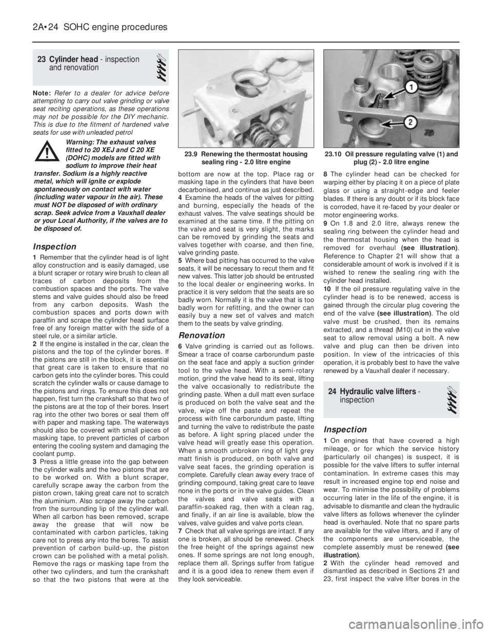
9On 1.8 and 2.0 litre, always renew the
sealing ring between the cylinder head and
the thermostat housing when the head is
removed for overhaul (see illustration).
Reference to Chapter 21 will show that a
considerable amount of work is involved if it is
wished to renew the sealing ring with the
cylinder head installed.
10If the oil pressure regulating valve in the
cylinder head is to be renewed, access is
gained through the circular plug covering the
end of the valve (see illustration). The old
valve must be crushed, then its remains
extracted, and a thread (M10) cut in the valve
seat to allow removal using a bolt. A new
valve and plug can then be driven into
position. In view of the intricacies of this
operation, it is probably best to have the valve
renewed by a Vauxhall dealer if necessary.
24Hydraulic valve lifters -
inspection
4
Inspection
1On engines that have covered a high
mileage, or for which the service history
(particularly oil changes) is suspect, it is
possible for the valve lifters to suffer internal
contamination. In extreme cases this may
result in increased engine top end noise and
wear. To minimise the possibility of problems
occurring later in the life of the engine, it is
advisable to dismantle and clean the hydraulic
valve lifters as follows whenever the cylinder
head is overhauled. Note that no spare parts
are available for the valve lifters, and if any of
the components are unserviceable, the
complete assembly must be renewed (see
illustration).
2With the cylinder head removed and
dismantled as described in Sections 21 and
23, first inspect the valve lifter bores in the
2A•24SOHC engine procedures
23.10 Oil pressure regulating valve (1) and
plug (2) - 2.0 litre engine23.9 Renewing the thermostat housing
sealing ring - 2.0 litre engine
Warning: The exhaust valves
fitted to 20 XEJ and C 20 XE
(DOHC) models are fitted with
sodium to improve their heat
transfer. Sodium is a highly reactive
metal, which will ignite or explode
spontaneously on contact with water
(including water vapour in the air). These
must NOT be disposed of with ordinary
scrap. Seek advice from a Vauxhall dealer
or your Local Authority, if the valves are to
be disposed of.
Page 226 of 525
Inspection
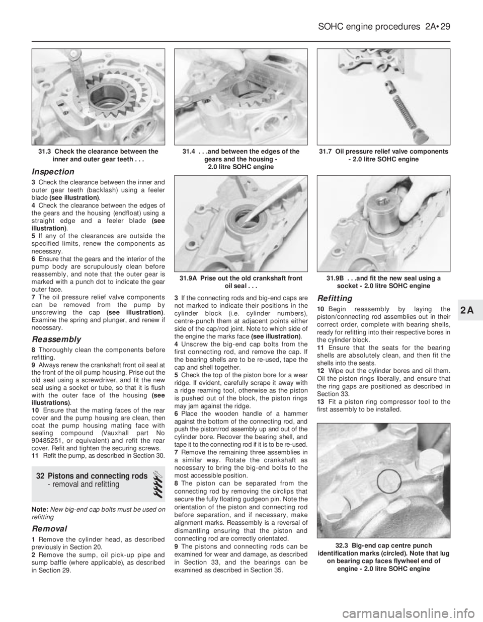
3Check the clearance between the inner and
outer gear teeth (backlash) using a feeler
blade (see illustration).
4Check the clearance between the edges of
the gears and the housing (endfloat) using a
straight edge and a feeler blade (see
illustration).
5If any of the clearances are outside the
specified limits, renew the components as
necessary.
6Ensure that the gears and the interior of the
pump body are scrupulously clean before
reassembly, and note that the outer gear is
marked with a punch dot to indicate the gear
outer face.
7The oil pressure relief valve components
can be removed from the pump by
unscrewing the cap (see illustration).
Examine the spring and plunger, and renew if
necessary.
Reassembly
8Thoroughly clean the components before
refitting.
9Always renew the crankshaft front oil seal at
the front of the oil pump housing. Prise out the
old seal using a screwdriver, and fit the new
seal using a socket or tube, so that it is flush
with the outer face of the housing (see
illustrations).
10Ensure that the mating faces of the rear
cover and the pump housing are clean, then
coat the pump housing mating face with
sealing compound (Vauxhall part No
90485251, or equivalent) and refit the rear
cover. Refit and tighten the securing screws.
11Refit the pump, as described in Section 30.
32Pistons and connecting rods
- removal and refitting
4
Note: New big-end cap bolts must be used on
refitting
Removal
1Remove the cylinder head, as described
previously in Section 20.
2Remove the sump, oil pick-up pipe and
sump baffle (where applicable), as described
in Section 29.3If the connecting rods and big-end caps are
not marked to indicate their positions in the
cylinder block (i.e. cylinder numbers),
centre-punch them at adjacent points either
side of the cap/rod joint. Note to which side of
the engine the marks face (see illustration).
4Unscrew the big-end cap bolts from the
first connecting rod, and remove the cap. If
the bearing shells are to be re-used, tape the
cap and shell together.
5Check the top of the piston bore for a wear
ridge. If evident, carefully scrape it away with
a ridge reaming tool, otherwise as the piston
is pushed out of the block, the piston rings
may jam against the ridge.
6Place the wooden handle of a hammer
against the bottom of the connecting rod, and
push the piston/rod assembly up and out of the
cylinder bore. Recover the bearing shell, and
tape it to the connecting rod if it is to be re-used.
7Remove the remaining three assemblies in
a similar way. Rotate the crankshaft as
necessary to bring the big-end bolts to the
most accessible position.
8The piston can be separated from the
connecting rod by removing the circlips that
secure the fully floating gudgeon pin. Note the
orientation of the piston and connecting rod
before separation, and if necessary, make
alignment marks. Reassembly is a reversal of
dismantling ensuring that the piston and
connecting rod are correctly orientated.
9The pistons and connecting rods can be
examined for wear and damage, as described
in Section 33, and the bearings can be
examined as described in Section 35.
Refitting
10Begin reassembly by laying the
piston/connecting rod assemblies out in their
correct order, complete with bearing shells,
ready for refitting into their respective bores in
the cylinder block.
11Ensure that the seats for the bearing
shells are absolutely clean, and then fit the
shells into the seats.
12Wipe out the cylinder bores and oil them.
Oil the piston rings liberally, and ensure that
the ring gaps are positioned as described in
Section 33.
13Fit a piston ring compressor tool to the
first assembly to be installed.
SOHC engine procedures 2A•29
31.7 Oil pressure relief valve components
- 2.0 litre SOHC engine
32.3 Big-end cap centre punch
identification marks (circled). Note that lug
on bearing cap faces flywheel end of
engine - 2.0 litre SOHC engine
31.9B . . .and fit the new seal using a
socket - 2.0 litre SOHC engine31.9A Prise out the old crankshaft front
oil seal . . .
31.4 . . .and between the edges of the
gears and the housing -
2.0 litre SOHC engine31.3 Check the clearance between the
inner and outer gear teeth . . .
2A
Page 228 of 525
7If any of the ring end gaps exceed the
specified tolerance, the relevant rings will have
to be renewed, and if the ring grooves in the
pistons are worn, new pistons may be required.
8Clean out the piston ring grooves using a
piece of old piston ring as a scraper. Take
care not to scratch the surface of the pistons.
Protect your fingers, piston ring edges are
sharp. Also probe the groove oil return holes,
to ensure that they are not blocked.
9Check the cylinder bores for signs of wear
ridges towards the top of the bores. If wear
ridges are evident, and new piston rings are
being fitted, the top ring must be stepped to
clear the wear ridge, or the bore must be
de-ridged using a scraper.
10Fit the oil control ring sections with the
lower steel ring gap offset 25 to 50 mm to the
right of the spreader ring gap, and the upper
steel ring gap offset by the same distance to
the left of the spreader ring gap.
11Fit the lower compression ring, noting that
the ring is tapered or stepped. The ring should
be fitted with the word “TOP” uppermost.
12Fit the upper compression ring, and offset
the ring gap by 180°to the lower compression
ring gap. If a stepped ring is being fitted, fit
the ring with the smaller diameter of the step
uppermost.
13If new pistons are to be fitted, they must
be selected from the grades available, after
measuring the cylinder bores as described in
Section 36.
14Normally the appropriate oversize pistons
are supplied by the dealer when the block is
rebored.15Whenever new piston rings are being
installed, the glaze on the original cylinder
bores should be “broken”, using either
abrasive paper or a glaze-removing tool in an
electric drill. If abrasive paper is used, use
strokes at 60°to the bore centre line, to create
a cross-hatching effect.
34Crankshaft and bearings -
removal and refitting
4
Note: New main bearing cap bolts must be
used on refitting
Removal
1With the engine removed from the vehicle,
continue as follows.
2Remove the cylinder head, as described
previously in Section 20.
3Remove the sump, oil pick-up pipe and
sump baffle (where applicable), as described
in Section 29.
4Remove the oil pump, as described in
Section 30.
5Remove the flywheel or flexplate (if
applicable), as described in Sections 25 and
26.
6Remove the pistons and connecting rods,
as described in Section 32.
7Invert the engine so that it is standing on
the top face of the cylinder block.
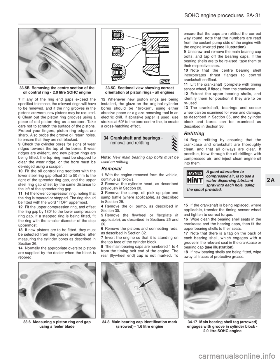
8The main bearing caps are numbered 1 to 4
from the timing belt end of the engine. The
rear (flywheel end) cap is not marked. Toensure that the caps are refitted the correct
way round, note that the numbers are read
from the coolant pump side of the engine with
the engine inverted (see illustration).
9Unscrew and remove the main bearing cap
bolts, and tap off the bearing caps. If the
bearing shells are to be re-used, tape them to
their respective caps.
10Note that the centre bearing shell
incorporates thrust flanges to control
crankshaft endfloat.
11Lift the crankshaft (complete with timing
sensor wheel, if fitted), from the crankcase.
12Extract the upper bearing shells, and
identify them for position if they are to be
re-used.
13The crankshaft, bearings and sensor
wheel can be examined for wear and damage,
as described in Section 35, and the cylinder
block and bores can be examined as
described in Section 36.
Refitting
14Begin refitting by ensuring that the
crankcase and crankshaft are thoroughly
clean, and that all oilways are clear. If
possible, blow through the oil drillings with
compressed air, and inject clean engine oil
into them.
15If the crankshaft is being replaced, where
applicable, transfer the timing sensor wheel
and tighten to correct torque.
16Wipe clean the bearing shell seats in the
crankcase and the bearing caps, then fit the
upper bearing shells to their seats.
17Note that there is a tag on the back of
each bearing shell, which engages with a
groove in the relevant seat in the crankcase or
bearing cap (see illustration).
18If new bearing shells are being fitted, wipe
away all traces of protective grease.
SOHC engine procedures 2A•31
33.6 Measuring a piston ring end gap
using a feeler blade34.8 Main bearing cap identification mark
(arrowed) - 1.6 litre engine34.17 Main bearing shell tag (arrowed)
engages with groove in cylinder block -
2.0 litre SOHC engine
33.5C Sectional view showing correct
orientation of piston rings - all engines33.5B Removing the centre section of the
oil control ring - 2.0 litre SOHC engine
2A
A good alternative to
compressed air, is to use a
water dispersing lubricant
spray into each hole, using
the spout provided.
Page 231 of 525
5Note that the rubber plug located next to
the bellhousing flange on the cylinder block
covers the aperture for the installation of a
diagnostic TDC sensor. The sensor, when
connected to a monitoring unit, indicates TDC
from the position of the pins set into the
crankshaft balance weight.
37Examination and renovation
-general
4
General
1With the engine completely stripped, clean all
components and examine them for wear. Each
component should be checked, and where
necessary renewed or renovated, as described
in the relevant Sections of this Chapter.
2Renew main and big-end bearing shells as
a matter of course, unless it is known that
they have had little wear, and are in perfect
condition.
3If in doubt whether to renew a component
that is still just serviceable, consider the time
and effort that will be incurred should the
component fail at an early date after rebuild.
Obviously, the age and expected life of the
vehicle must influence the standards applied.4Gaskets, oil seals and O-rings must all be
renewed as a matter of routine. Flywheel,
cylinder head, and main and big-end bearing
cap bolts must be renewed, because of the
high stress to which they are subjected.
5Renew the engine core plugs while they are
easily accessible, if they show signs of
leakage. Knock out the old plugs with a
hammer and chisel or punch. Clean the plug
seats, smear the new plugs with sealing
compound, and tap them squarely into
position.
38Initial start-up after major
overhaul or repair
2
1Make a final check to ensure that
everything has been reconnected to the
engine, and that no rags or tools have been
left in the engine compartment.
2Check that oil and coolant levels are
correct.
3Start the engine. This may take a little longer
than usual, as fuel is pumped to the engine.
4Check that the oil pressure warning lamp
goes out when the engine starts. This may
take a few seconds as the new oil filter fills
with oil.5Run the engine at a fast tickover, and check
for leaks of oil, fuel and coolant. If a new
camshaft has been fitted, pay careful
attention to the running-in procedure given in
Section 18, paragraphs 17 and 18. Where
applicable, check the power steering and/or
automatic transmission fluid cooler unions for
leakage. Some smoke and odd smells may be
experienced, as assembly lubricants and
sealers burn off the various components.
6Bring the engine to normal operating
temperature. Check the ignition timing, idle
speed and the mixture (where applicable), as
described in Chapter 4A or 4B.
7Allow the engine to cool, then recheck the
oil and coolant levels. Top-up if necessary
8If new bearings, pistons, etc., have been
fitted, the engine should be run-in at reduced
speeds and loads for the first 500 miles (800
km) or so. It is beneficial to change the engine
oil and filter after this mileage.
2A•34SOHC engine procedures