1988 OPEL VECTRA service indicator
[x] Cancel search: service indicatorPage 129 of 525

b)Always keep the ignition and fuel systems
well maintained according to the
manufacturers schedule (see “Routine
maintenance” and the relevant Chapter).
In particular, ensure that the air cleaner
filter element, the fuel filter and the spark
plugs are renewed at the correct intervals.
If the inlet air/fuel mixture is allowed to
become too rich due to neglect, the
unburned surplus will enter and burn in
the catalytic converter, overheating the
element and eventually destroying the
converter.
c)If the engine develops a misfire, do not
drive the vehicle at all (or at least as little
as possible) until the fault is cured. The
misfire will allow unburned fuel to enter
the converter, which will result in its
overheating, as noted above.
d)The engine control indicator (the outline
of an engine with a lightning symbol
superimposed), will light when the ignition
is switched on and the engine is started,
then it will go out. While it may light briefly
while the engine is running, it should go
out again immediately and stays unlit. If it
lights and stays on while the engine is
running, seek the advice of a Vauxhall
dealer as soon as possible. A fault has
occurred in the fuel injection/ignition
system that, apart from increasing fuel
consumption and impairing the engine’s
performance, may damage the catalytic
converter.
e)DO NOT push or tow-start the vehicle.
This will soak the catalytic converter in
unburned fuel causing it to overheat when
the engine does start see (b) above.
f)DO NOT switch off the ignition at high
engine speeds. If the ignition is switched
off at anything above idle speed,
unburned fuel will enter the (very hot)
catalytic converter, with the possible risk
of its igniting on the element and
damaging the converter.
g)DO NOT use fuel or engine oil additives.
These may contain substances harmful to
the catalytic converter.
h)DO NOT continue to use the vehicle if the
engine burns oil to the extent of leaving a
visible trail of blue smoke. The unburned
carbon deposits will clog the converter
passages and reduce its efficiency; in
severe cases the element will overheat.
i)Remember that the catalytic converter
operates at very high temperatures hence
the heat shields on the vehicle’s under-
body and the casing will become hot
enough to ignite combustible materials
that brush against it. DO NOT, therefore,
park the vehicle in dry undergrowth, over
long grass or over piles of dead leaves.
j)Remember that the catalytic converter is
FRAGlLE. Do not strike it with tools during
servicing work. Take great care when
working on the exhaust system. Ensure
that the converter is well clear of any
jacks or other lifting gear used to raise thevehicle. Do not drive the vehicle over
rough ground, road humps, etc., in such a
way as to ground the exhaust system.
k)In some cases, particularly when the
vehicle is new and/or is used for
stop/start driving, a sulphurous smell (like
that of rotten eggs) may be noticed from
the exhaust. This is common to many
catalytic converter-equipped vehicles and
seems to be due to the small amount of
sulphur found in some petrol’s reacting
with hydrogen in the exhaust to produce
hydrogen sulphide (CS) gas. While this
gas is toxic, it is not produced in sufficient
amounts to be a problem. Once the
vehicle has covered a few thousand miles
the problem should disappear. In the
meanwhile a change of driving style or of
the brand of petrol may effect a solution.
l)The catalytic converter, used on a
well-maintained and well-driven vehicle,
should last for between 50 000 and 100
000 miles. From this point on, careful
checks should be made at all specified
service intervals of the CO level to ensure
that the converter is still operating
efficiently. If the converter is no longer
effective it must be renewed.
11Carbon canister - removal
and refitting
3
Removal
1Apply the handbrake, then jack up the front
of the vehicle, and support securely on axle
stands placed under the body side members
(see “Jacking and Vehicle Support”).
2Remove the front right hand wheel and
wheel arch liner.
3Note the hose and pipe connections to the
canister, or label them, to ensure that they are
reconnected to their original unions, then
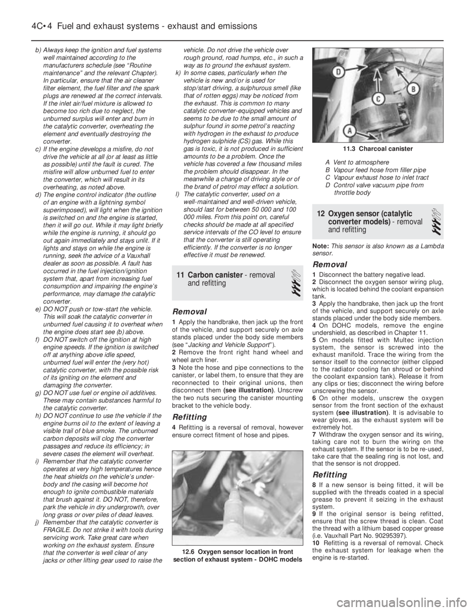
disconnect them (see illustration). Unscrew
the two nuts securing the canister mounting
bracket to the vehicle body.
Refitting
4Refitting is a reversal of removal, however
ensure correct fitment of hose and pipes.
12Oxygen sensor (catalytic
converter models) - removal
and refitting
3
Note: This sensor is also known as a Lambda
sensor.
Removal
1Disconnect the battery negative lead.
2Disconnect the oxygen sensor wiring plug,
which is located behind the coolant expansion
tank.
3Apply the handbrake, then jack up the front
of the vehicle, and support securely on axle
stands placed under the body side members.
4On DOHC models, remove the engine
undershield, as described in Chapter 11.
5On models fitted with Multec injection
system, the sensor is screwed into the
exhaust manifold. Trace the wiring from the
sensor itself to the connector (either clipped
to the radiator cooling fan shroud or behind
the coolant expansion tank). Release it from
any clips or ties; disconnect the wiring before
unscrewing the sensor.
6On other models, unscrew the oxygen
sensor from the front section of the exhaust
system (see illustration). It is advisable to
wear gloves, as the exhaust system will be
extremely hot.
7Withdraw the oxygen sensor and its wiring,
taking care not to burn the wiring on the
exhaust system. If the sensor is to be re-used,
take care that the sealing ring is not lost, and
that the sensor is not dropped.
Refitting
8If a new sensor is being fitted, it will be
supplied with the threads coated in a special
grease to prevent it seizing in the exhaust
system.
9If the original sensor is being refitted,
ensure that the screw thread is clean. Coat
the thread with a lithium based copper grease
(i.e. Vauxhall Part No. 90295397).
10Refitting is a reversal of removal. Check
the exhaust system for leakage when the
engine is re-started.
4C•4Fuel and exhaust systems - exhaust and emissions
12.6 Oxygen sensor location in front
section of exhaust system - DOHC models
11.3 Charcoal canister
A Vent to atmosphere
B Vapour feed hose from filler pipe
C Vapour exhaust hose to inlet tract
D Control valve vacuum pipe from
throttle body
Page 246 of 525

Tools and Working Facilities REF•7
REF
Special tools
The tools in this list are those which are not
used regularly, are expensive to buy, or which
need to be used in accordance with their
manufacturers’ instructions. Unless relatively
difficult mechanical jobs are undertaken
frequently, it will not be economic to buy
many of these tools. Where this is the case,
you could consider clubbing together with
friends (or joining a motorists’ club) to make a
joint purchase, or borrowing the tools against
a deposit from a local garage or tool hire
specialist. It is worth noting that many of the
larger DIY superstores now carry a large
range of special tools for hire at modest rates.
The following list contains only those tools
and instruments freely available to the public,
and not those special tools produced by the
vehicle manufacturer specifically for its dealer
network. You will find occasional references
to these manufacturers’ special tools in the
text of this manual. Generally, an alternative
method of doing the job without the vehicle
manufacturers’ special tool is given. However,
sometimes there is no alternative to using
them. Where this is the case and the relevant
tool cannot be bought or borrowed, you will
have to entrust the work to a dealer.
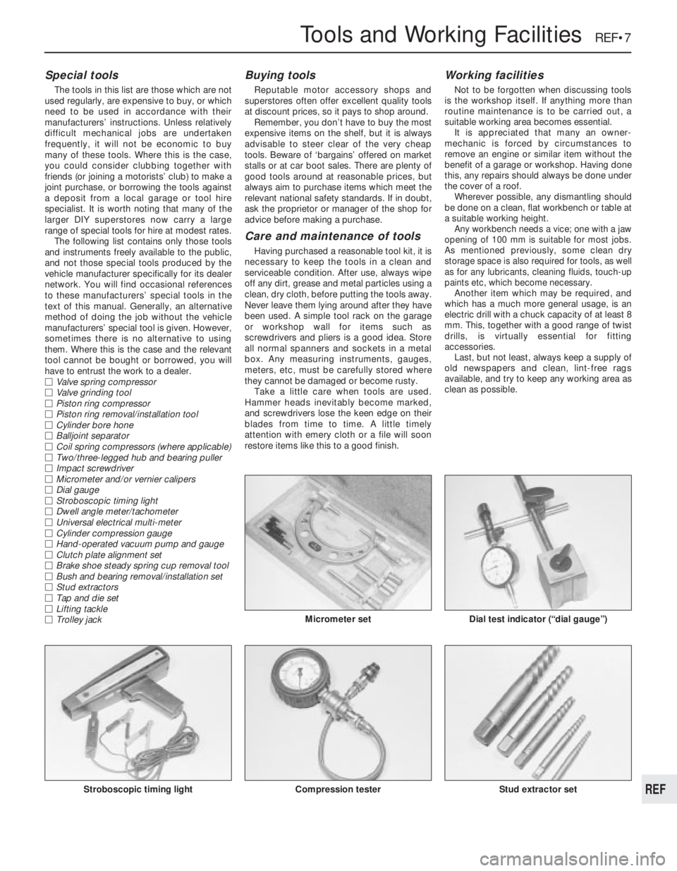
MValve spring compressor
MValve grinding tool
MPiston ring compressor
MPiston ring removal/installation tool
MCylinder bore hone
MBalljoint separator
MCoil spring compressors (where applicable)
MTwo/three-legged hub and bearing puller
MImpact screwdriver
MMicrometer and/or vernier calipers
MDial gauge
MStroboscopic timing light
MDwell angle meter/tachometer
MUniversal electrical multi-meter
MCylinder compression gauge
MHand-operated vacuum pump and gauge
MClutch plate alignment set
MBrake shoe steady spring cup removal tool
MBush and bearing removal/installation set
MStud extractors
MTap and die set
MLifting tackle
MTrolley jack
Buying tools
Reputable motor accessory shops and
superstores often offer excellent quality tools
at discount prices, so it pays to shop around.
Remember, you don’t have to buy the most
expensive items on the shelf, but it is always
advisable to steer clear of the very cheap
tools. Beware of ‘bargains’ offered on market
stalls or at car boot sales. There are plenty of
good tools around at reasonable prices, but
always aim to purchase items which meet the
relevant national safety standards. If in doubt,
ask the proprietor or manager of the shop for
advice before making a purchase.
Care and maintenance of tools
Having purchased a reasonable tool kit, it is
necessary to keep the tools in a clean and
serviceable condition. After use, always wipe
off any dirt, grease and metal particles using a
clean, dry cloth, before putting the tools away.
Never leave them lying around after they have
been used. A simple tool rack on the garage
or workshop wall for items such as
screwdrivers and pliers is a good idea. Store
all normal spanners and sockets in a metal
box. Any measuring instruments, gauges,
meters, etc, must be carefully stored where
they cannot be damaged or become rusty.
Take a little care when tools are used.
Hammer heads inevitably become marked,
and screwdrivers lose the keen edge on their
blades from time to time. A little timely
attention with emery cloth or a file will soon
restore items like this to a good finish.
Working facilities
Not to be forgotten when discussing tools
is the workshop itself. If anything more than
routine maintenance is to be carried out, a
suitable working area becomes essential.
It is appreciated that many an owner-
mechanic is forced by circumstances to
remove an engine or similar item without the
benefit of a garage or workshop. Having done
this, any repairs should always be done under
the cover of a roof.
Wherever possible, any dismantling should
be done on a clean, flat workbench or table at
a suitable working height.
Any workbench needs a vice; one with a jaw
opening of 100 mm is suitable for most jobs.
As mentioned previously, some clean dry
storage space is also required for tools, as well
as for any lubricants, cleaning fluids, touch-up
paints etc, which become necessary.
Another item which may be required, and
which has a much more general usage, is an
electric drill with a chuck capacity of at least 8
mm. This, together with a good range of twist
drills, is virtually essential for fitting
accessories.
Last, but not least, always keep a supply of
old newspapers and clean, lint-free rags
available, and try to keep any working area as
clean as possible.
Stroboscopic timing light Stud extractor setCompression tester
Dial test indicator (“dial gauge”)Micrometer set
Page 255 of 525

Note:Due to the complexity of the automatic transmission, it is difficult
for the home mechanic to properly diagnose and service this unit. For
problems other than the following, the vehicle should be taken to a
dealer service department or automatic transmission specialist. Do not
be too hasty in removing the transmission if a fault is suspected, as
most of the testing is carried out with the unit still fitted.
Fluid leakage
MAutomatic transmission fluid is usually dark in colour. Fluid leaks
should not be confused with engine oil, which can easily be blown
onto the transmission by airflow.
MTo determine the source of a leak, first remove all built-up dirt and
grime from the transmission housing and surrounding areas using
a degreasing agent, or by steam-cleaning. Drive the vehicle at low
speed, so airflow will not blow the leak far from its source. Raise
and support the vehicle, and determine where the leak is coming
from. The following are common areas of leakage:
a)Fluid pan or “sump” (Chapter 1 and 7B).
b)Dipstick tube (Chapter 1 and 7B).
c)Transmission-to-fluid cooler pipes/unions (Chapter 7B).
Transmission fluid brown, or has burned smell
MTransmission fluid level low, or fluid in need of renewal (Chapter 1).
General gear selection problems
MChapter 7B deals with checking and adjusting the selector cable
on automatic transmissions. The following are common problems
that may be caused by a poorly adjusted cable:a)Engine starting in gears other than Park or Neutral.
b)Indicator panel indicating a gear other than the one actually being
used.
c)Vehicle moves when in Park or Neutral.
d)Poor gear shift quality or erratic gear changes.
MRefer to Chapter 7B for the selector cable adjustment procedure.
Transmission will not downshift (kickdown) with
accelerator pedal fully depressed
MLow transmission fluid level (Chapter 1).
MIncorrect selector cable adjustment (Chapter 7B).
Engine will not start in any gear, or starts in gears
other than Park or Neutral
MIncorrect starter/inhibitor switch adjustment (Chapter 7B).
MIncorrect selector cable adjustment (Chapter 7B).
Transmission slips, shifts roughly, is noisy, or has
no drive in forward or reverse gears
MThere are many probable causes for the above problems, but the
home mechanic should be concerned with only one possibility -
fluid level. Before taking the vehicle to a dealer or transmission
specialist, check the fluid level and condition of the fluid as
described in Chapter 1. Correct the fluid level as necessary, or
change the fluid and filter if needed. If the problem persists,
professional help will be necessary.
Clicking or knocking noise on turns (at slow speed
on full-lock)
MLack of constant velocity joint lubricant, possibly due to damaged
gaiter (Chapter 8).
MWorn outer constant velocity joint (Chapter 8).
Vibration when accelerating or decelerating
MWorn inner constant velocity joint (Chapter 8).
MBent or distorted driveshaft (Chapter 8).
REF•16Fault Finding
Automatic transmission
Driveshafts
Noisy in neutral with engine running
MInput shaft bearings worn (noise apparent with clutch pedal
released, but not when depressed), (Chapter 7A).*
MClutch release bearing worn (noise apparent with clutch pedal
depressed, possibly less when released), (Chapter 6).
Noisy in one particular gear
MWorn, damaged or chipped gear teeth (Chapter 7A).*
Difficulty engaging gears
MClutch fault (Chapter 6).
MWorn or damaged gear linkage (Chapter 7A).
MIncorrectly adjusted gear linkage (Chapter 7A).
MWorn synchroniser units (Chapter 7A).*
Jumps out of gear
MWorn or damaged gear linkage (Chapter 7A).
MIncorrectly adjusted gear linkage (Chapter 7A).MWorn synchroniser units (Chapter 7A).*
MWorn selector forks (Chapter 7A).*
Vibration
MLack of oil (Chapter 1).
MWorn bearings (Chapter 7A).*
Lubricant leaks
MLeaking differential output oil seal (Chapter 7A).
MLeaking housing joint (Chapter 7A).*
MLeaking input shaft oil seal (Chapter 7A).*
* Although the corrective action necessary to remedy the symptoms
described is beyond the scope of the home mechanic, the above
information should be helpful in isolating the cause of the condition.
This should enable the owner can communicate clearly with a
professional mechanic.
Manual transmission