1988 OPEL VECTRA ESP
[x] Cancel search: ESPPage 155 of 525
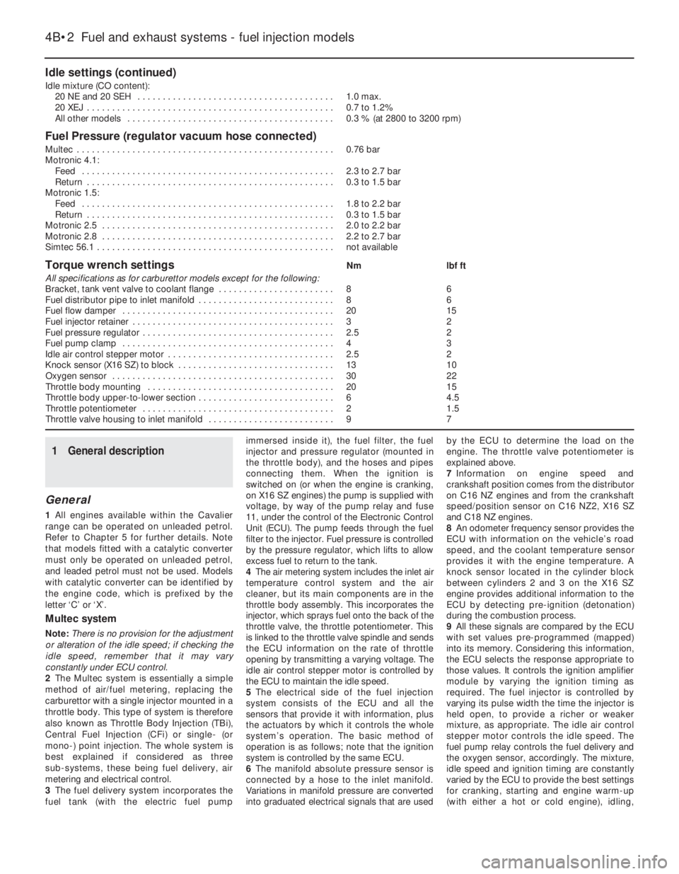
Idle settings (continued)
Idle mixture (CO content):
20 NE and 20 SEH . . . . . . . . . . . . . . . . . . . . . . . . . . . . . . . . . . . . . . .1.0 max.
20 XEJ . . . . . . . . . . . . . . . . . . . . . . . . . . . . . . . . . . . . . . . . . . . . . . . . .0.7 to 1.2%
All other models . . . . . . . . . . . . . . . . . . . . . . . . . . . . . . . . . . . . . . . . .0.3 % (at 2800 to 3200 rpm)
Fuel Pressure (regulator vacuum hose connected)
Multec . . . . . . . . . . . . . . . . . . . . . . . . . . . . . . . . . . . . . . . . . . . . . . . . . . .0.76 bar
Motronic 4.1:
Feed . . . . . . . . . . . . . . . . . . . . . . . . . . . . . . . . . . . . . . . . . . . . . . . . . .2.3 to 2.7 bar
Return . . . . . . . . . . . . . . . . . . . . . . . . . . . . . . . . . . . . . . . . . . . . . . . . .0.3 to 1.5 bar
Motronic 1.5:
Feed . . . . . . . . . . . . . . . . . . . . . . . . . . . . . . . . . . . . . . . . . . . . . . . . . .1.8 to 2.2 bar
Return . . . . . . . . . . . . . . . . . . . . . . . . . . . . . . . . . . . . . . . . . . . . . . . . .0.3 to 1.5 bar
Motronic 2.5 . . . . . . . . . . . . . . . . . . . . . . . . . . . . . . . . . . . . . . . . . . . . . .2.0 to 2.2 bar
Motronic 2.8 . . . . . . . . . . . . . . . . . . . . . . . . . . . . . . . . . . . . . . . . . . . . . .2.2 to 2.7 bar
Simtec 56.1 . . . . . . . . . . . . . . . . . . . . . . . . . . . . . . . . . . . . . . . . . . . . . . .not available
Torque wrench settingsNmlbf ft
All specifications as for carburettor models except for the following:
Bracket, tank vent valve to coolant flange . . . . . . . . . . . . . . . . . . . . . . .86
Fuel distributor pipe to inlet manifold . . . . . . . . . . . . . . . . . . . . . . . . . . .86
Fuel flow damper . . . . . . . . . . . . . . . . . . . . . . . . . . . . . . . . . . . . . . . . . .2015
Fuel injector retainer . . . . . . . . . . . . . . . . . . . . . . . . . . . . . . . . . . . . . . . .32
Fuel pressure regulator . . . . . . . . . . . . . . . . . . . . . . . . . . . . . . . . . . . . . .2.52
Fuel pump clamp . . . . . . . . . . . . . . . . . . . . . . . . . . . . . . . . . . . . . . . . . .43
Idle air control stepper motor . . . . . . . . . . . . . . . . . . . . . . . . . . . . . . . . .2.52
Knock sensor (X16 SZ) to block . . . . . . . . . . . . . . . . . . . . . . . . . . . . . . .1310
Oxygen sensor . . . . . . . . . . . . . . . . . . . . . . . . . . . . . . . . . . . . . . . . . . . .3022
Throttle body mounting . . . . . . . . . . . . . . . . . . . . . . . . . . . . . . . . . . . . .2015
Throttle body upper-to-lower section . . . . . . . . . . . . . . . . . . . . . . . . . . .64.5
Throttle potentiometer . . . . . . . . . . . . . . . . . . . . . . . . . . . . . . . . . . . . . .21.5
Throttle valve housing to inlet manifold . . . . . . . . . . . . . . . . . . . . . . . . .97
1General description
General
1All engines available within the Cavalier
range can be operated on unleaded petrol.
Refer to Chapter 5 for further details. Note
that models fitted with a catalytic converter
must only be operated on unleaded petrol,
and leaded petrol must not be used. Models
with catalytic converter can be identified by
the engine code, which is prefixed by the
letter ‘C’ or ‘X’.
Multec system
Note: There is no provision for the adjustment
or alteration of the idle speed; if checking the
idle speed, remember that it may vary
constantly under ECU control.
2The Multec system is essentially a simple
method of air/fuel metering, replacing the
carburettor with a single injector mounted in a
throttle body. This type of system is therefore
also known as Throttle Body Injection (TBi),
Central Fuel Injection (CFi) or single-(or
mono-) point injection. The whole system is
best explained if considered as three
sub-systems, these being fuel delivery, air
metering and electrical control.
3The fuel delivery system incorporates the
fuel tank (with the electric fuel pumpimmersed inside it), the fuel filter, the fuel
injector and pressure regulator (mounted in
the throttle body), and the hoses and pipes
connecting them. When the ignition is
switched on (or when the engine is cranking,
on X16 SZ engines) the pump is supplied with
voltage, by way of the pump relay and fuse
11, under the control of the Electronic Control
Unit (ECU). The pump feeds through the fuel
filter to the injector. Fuel pressure is controlled
by the pressure regulator, which lifts to allow
excess fuel to return to the tank.
4The air metering system includes the inlet air
temperature control system and the air
cleaner, but its main components are in the
throttle body assembly. This incorporates the
injector, which sprays fuel onto the back of the
throttle valve, the throttle potentiometer. This
is linked to the throttle valve spindle and sends
the ECU information on the rate of throttle
opening by transmitting a varying voltage. The
idle air control stepper motor is controlled by
the ECU to maintain the idle speed.
5The electrical side of the fuel injection
system consists of the ECU and all the
sensors that provide it with information, plus
the actuators by which it controls the whole
system’s operation. The basic method of
operation is as follows; note that the ignition
system is controlled by the same ECU.
6The manifold absolute pressure sensor is
connected by a hose to the inlet manifold.
Variations in manifold pressure are converted
into graduated electrical signals that are usedby the ECU to determine the load on the
engine. The throttle valve potentiometer is
explained above.
7Information on engine speed and
crankshaft position comes from the distributor
on C16 NZ engines and from the crankshaft
speed/position sensor on C16 NZ2, X16 SZ
and C18 NZ engines.
8An odometer frequency sensor provides the
ECU with information on the vehicle’s road
speed, and the coolant temperature sensor
provides it with the engine temperature. A
knock sensor located in the cylinder block
between cylinders 2 and 3 on the X16 SZ
engine provides additional information to the
ECU by detecting pre-ignition (detonation)
during the combustion process.
9All these signals are compared by the ECU
with set values pre-programmed (mapped)
into its memory. Considering this information,
the ECU selects the response appropriate to
those values. It controls the ignition amplifier
module by varying the ignition timing as
required. The fuel injector is controlled by
varying its pulse width the time the injector is
held open, to provide a richer or weaker
mixture, as appropriate. The idle air control
stepper motor controls the idle speed. The
fuel pump relay controls the fuel delivery and
the oxygen sensor, accordingly. The mixture,
idle speed and ignition timing are constantly
varied by the ECU to provide the best settings
for cranking, starting and engine warm-up
(with either a hot or cold engine), idling,
4B•2Fuel and exhaust systems - fuel injection models
Page 181 of 525
2Also check the security and condition of all
the engine related pipes and hoses. Ensure
that all cable-ties or securing clips are in
place, and in good condition. Clips that are
broken or missing can lead to chafing of the
hoses, pipes or wiring, which could cause
more serious problems in the future.
3Carefully check the radiator hoses and
heater hoses along their entire length. Renew
any hose that is cracked, swollen or
deteriorated. Cracks will show up better if the
hose is squeezed. Pay close attention to the
hose clips that secure the hoses to the
cooling system components. Hose clips can
pinch and puncture hoses, resulting in cooling
system leaks. It is always beneficial to renew
hose clips whenever possible.
4Inspect all the cooling system components
(hoses, joint faces, etc.) for leaks.
5Where any problems are found on system
components, renew the component or gasket
with reference to Chapter 3.
6Where applicable, inspect the automatic
transmission fluid cooler hoses for leaks or
deterioration.
7With the vehicle raised, inspect the petrol
tank and filler neck for punctures, cracks and
other damage. The connection between the
filler neck and tank is especially critical.
Sometimes a rubber filler neck or connecting
hose will leak due to loose retaining clamps or
deteriorated rubber.
8Carefully check all rubber hoses and metal
fuel lines leading away from the petrol tank.
Check for loose connections, deteriorated
hoses, crimped lines, and other damage. Pay
particular attention to the vent pipes and
hoses, which often loop up around the filler
neck and can become blocked or crimped.
Follow the lines to the front of the vehicle,
carefully inspecting them all the way. Renew
damaged sections as necessary.
9From within the engine compartment,
check the security of all fuel hose attachments
and pipe unions, and inspect the fuel hoses
and vacuum hoses for kinks, chafing and
deterioration.
10Where applicable, check the condition of
the power steering fluid hoses and pipes.5Steering and suspension
check
2
Front suspension and steering
check
1Raise the front of the car, and support on
axle stands (“Jacking and Vehicle Support”).
2Visually inspect the balljoint dust covers
and the steering rack-and-pinion gaiters for
splits, chafing or deterioration. Any wear of
these components will cause loss of lubricant,
together with dirt and water entry, resulting in
rapid wear of the balljoints or steering gear.
3On vehicles with power steering, check the
fluid hoses for chafing or deterioration, and
the pipe and hose unions for fluid leaks. Also
check for signs of fluid leakage under
pressure from the steering gear rubber
gaiters, which would indicate failed fluid seals
within the steering gear.
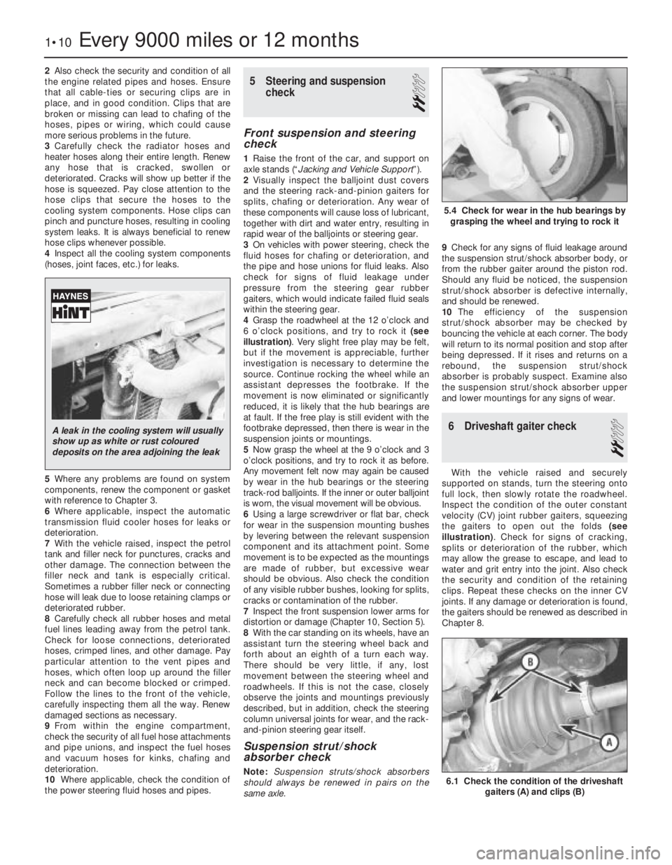
4Grasp the roadwheel at the 12 o’clock and
6 o’clock positions, and try to rock it (see
illustration). Very slight free play may be felt,
but if the movement is appreciable, further
investigation is necessary to determine the
source. Continue rocking the wheel while an
assistant depresses the footbrake. If the
movement is now eliminated or significantly
reduced, it is likely that the hub bearings are
at fault. If the free play is still evident with the
footbrake depressed, then there is wear in the
suspension joints or mountings.
5Now grasp the wheel at the 9 o’clock and 3
o’clock positions, and try to rock it as before.
Any movement felt now may again be caused
by wear in the hub bearings or the steering
track-rod balljoints. If the inner or outer balljoint
is worn, the visual movement will be obvious.
6Using a large screwdriver or flat bar, check
for wear in the suspension mounting bushes
by levering between the relevant suspension
component and its attachment point. Some
movement is to be expected as the mountings
are made of rubber, but excessive wear
should be obvious. Also check the condition
of any visible rubber bushes, looking for splits,
cracks or contamination of the rubber.
7Inspect the front suspension lower arms for
distortion or damage (Chapter 10, Section 5).
8With the car standing on its wheels, have an
assistant turn the steering wheel back and
forth about an eighth of a turn each way.
There should be very little, if any, lost
movement between the steering wheel and
roadwheels. If this is not the case, closely
observe the joints and mountings previously
described, but in addition, check the steering
column universal joints for wear, and the rack-
and-pinion steering gear itself.
Suspension strut/shock
absorber check
Note:Suspension struts/shock absorbers
should always be renewed in pairs on the
same axle.9Check for any signs of fluid leakage around
the suspension strut/shock absorber body, or
from the rubber gaiter around the piston rod.
Should any fluid be noticed, the suspension
strut/shock absorber is defective internally,
and should be renewed.
10The efficiency of the suspension
strut/shock absorber may be checked by
bouncing the vehicle at each corner. The body
will return to its normal position and stop after
being depressed. If it rises and returns on a
rebound, the suspension strut/shock
absorber is probably suspect. Examine also
the suspension strut/shock absorber upper
and lower mountings for any signs of wear.
6Driveshaft gaiter check
2
With the vehicle raised and securely
supported on stands, turn the steering onto
full lock, then slowly rotate the roadwheel.
Inspect the condition of the outer constant
velocity (CV) joint rubber gaiters, squeezing
the gaiters to open out the folds (see
illustration). Check for signs of cracking,
splits or deterioration of the rubber, which
may allow the grease to escape, and lead to
water and grit entry into the joint. Also check
the security and condition of the retaining
clips. Repeat these checks on the inner CV
joints. If any damage or deterioration is found,
the gaiters should be renewed as described in
Chapter 8.
1•10Every 9000 miles or 12 months
6.1 Check the condition of the driveshaft
gaiters (A) and clips (B)
5.4 Check for wear in the hub bearings by
grasping the wheel and trying to rock it
A leak in the cooling system will usually
show up as white or rust coloured
deposits on the area adjoining the leak
Page 182 of 525
At the same time, check the general
condition of the CV joints themselves by first
holding the driveshaft and attempting to
rotate the wheel. Repeat this check by holding
the inner joint and attempting to rotate the
driveshaft. Any appreciable movement
indicates wear in the joints, wear in the
driveshaft splines, or a loose driveshaft
retaining nut.
7Automatic transmission fluid
level check
2
Note: The transmission fluid level can be
checked either when it is cold (only below
35ºC (100ºF) outside temperature) or when it is
fully warmed up to normal operating
temperature (after driving for a distance of
approximately 12 miles/20 km). Since the fluid
level must be checked with the engine
running, ensure that the vehicle is parked on
level ground with the handbrake firmly applied
before leaving the driver’s seat. Be careful to
keep loose clothing, long hair, etc., well clear
of hot or moving components when working
under the bonnet
Transmission cold
1Park the vehicle on level ground and apply
the handbrake firmly. With the engine running
at no more than idle speed and your foot
firmly on the brake pedal, move the selector
lever through all positions, ending in position
“P”. Allow the engine to idle for one minute,
then check the level within two minutes.
2With the engine still idling and position “P”
still selected, open the bonnet and withdraw
the transmission dipstick from the filler tube
located in the front of the transmission casing,
at the left-hand end of the engine.
3Note the fluid’s condition (see below), then
wipe clean the dipstick using a clean,
non-fluffy rag, insert it fully back into the tube
and withdraw it again.
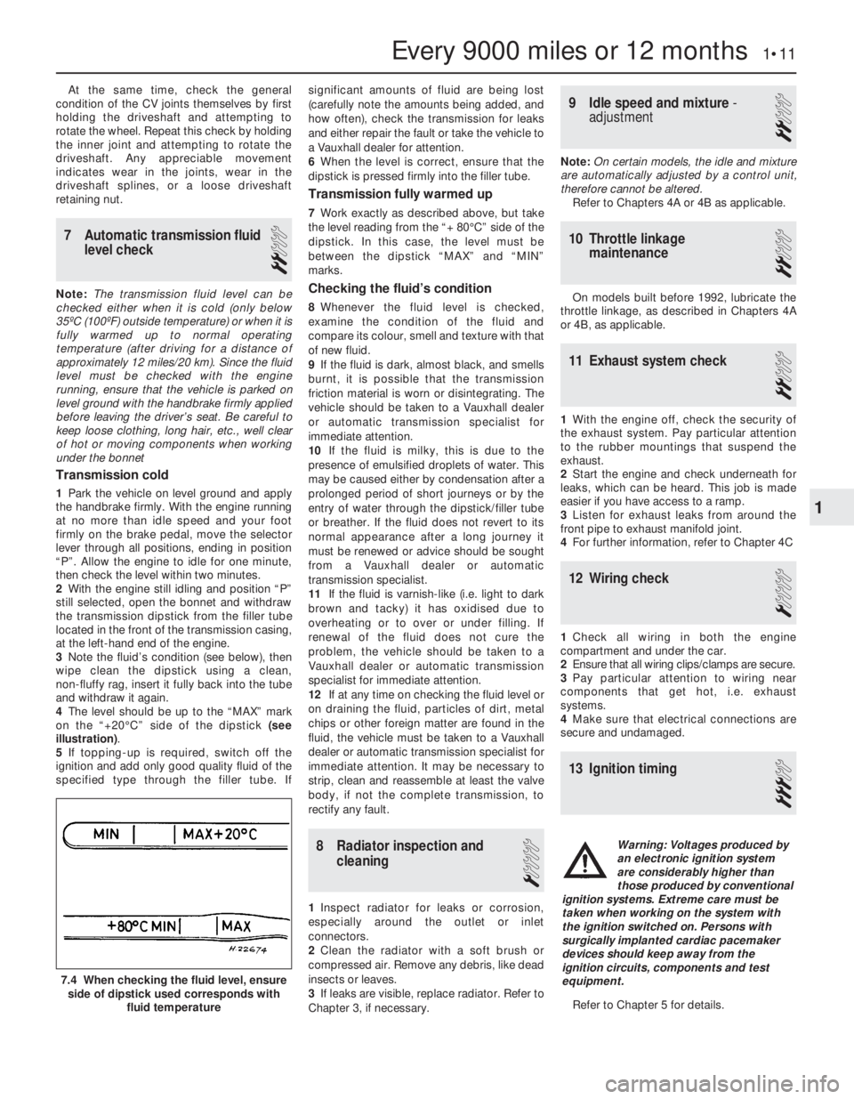
4The level should be up to the “MAX” mark
on the “+20°C” side of the dipstick (see
illustration).
5If topping-up is required, switch off the
ignition and add only good quality fluid of the
specified type through the filler tube. Ifsignificant amounts of fluid are being lost
(carefully note the amounts being added, and
how often), check the transmission for leaks
and either repair the fault or take the vehicle to
a Vauxhall dealer for attention.
6When the level is correct, ensure that the
dipstick is pressed firmly into the filler tube.
Transmission fully warmed up
7Work exactly as described above, but take
the level reading from the “+ 80°C” side of the
dipstick. In this case, the level must be
between the dipstick “MAX” and “MIN”
marks.
Checking the fluid’s condition
8Whenever the fluid level is checked,
examine the condition of the fluid and
compare its colour, smell and texture with that
of new fluid.
9If the fluid is dark, almost black, and smells
burnt, it is possible that the transmission
friction material is worn or disintegrating. The
vehicle should be taken to a Vauxhall dealer
or automatic transmission specialist for
immediate attention.
10If the fluid is milky, this is due to the
presence of emulsified droplets of water. This
may be caused either by condensation after a
prolonged period of short journeys or by the
entry of water through the dipstick/filler tube
or breather. If the fluid does not revert to its
normal appearance after a long journey it
must be renewed or advice should be sought
from a Vauxhall dealer or automatic
transmission specialist.
11If the fluid is varnish-like (i.e. light to dark
brown and tacky) it has oxidised due to
overheating or to over or under filling. If
renewal of the fluid does not cure the
problem, the vehicle should be taken to a
Vauxhall dealer or automatic transmission
specialist for immediate attention.
12If at any time on checking the fluid level or
on draining the fluid, particles of dirt, metal
chips or other foreign matter are found in the
fluid, the vehicle must be taken to a Vauxhall
dealer or automatic transmission specialist for
immediate attention. It may be necessary to
strip, clean and reassemble at least the valve
body, if not the complete transmission, to
rectify any fault.
8Radiator inspection and
cleaning
1
1Inspect radiator for leaks or corrosion,
especially around the outlet or inlet
connectors.
2Clean the radiator with a soft brush or
compressed air. Remove any debris, like dead
insects or leaves.
3If leaks are visible, replace radiator. Refer to
Chapter 3, if necessary.
9Idle speed and mixture -
adjustment
2
Note: On certain models, the idle and mixture
are automatically adjusted by a control unit,
therefore cannot be altered.
Refer to Chapters 4A or 4B as applicable.
10Throttle linkage
maintenance
2
On models built before 1992, lubricate the
throttle linkage, as described in Chapters 4A
or 4B, as applicable.
11Exhaust system check
2
1With the engine off, check the security of
the exhaust system. Pay particular attention
to the rubber mountings that suspend the
exhaust.
2Start the engine and check underneath for
leaks, which can be heard. This job is made
easier if you have access to a ramp.
3Listen for exhaust leaks from around the
front pipe to exhaust manifold joint.
4For further information, refer to Chapter 4C
12Wiring check
1
1Check all wiring in both the engine
compartment and under the car.
2Ensure that all wiring clips/clamps are secure.
3Pay particular attention to wiring near
components that get hot, i.e. exhaust
systems.
4Make sure that electrical connections are
secure and undamaged.
13Ignition timing
3
Refer to Chapter 5 for details.
Every 9000 miles or 12 months 1•11
7.4 When checking the fluid level, ensure
side of dipstick used corresponds with
fluid temperature
1
Warning: Voltages produced by
an electronic ignition system
are considerably higher than
those produced by conventional
ignition systems. Extreme care must be
taken when working on the system with
the ignition switched on. Persons with
surgically implanted cardiac pacemaker
devices should keep away from the
ignition circuits, components and test
equipment.
Page 183 of 525
14Brake fluid renewal
3
Renew the brake and bleed the system.
Refer to Chapter 9 for full details.
15Brake pad check
2
With the front or rear (as applicable) of the
vehicle raised, remove the wheels and check
brake pads for wear. Renew the pads if the
lining is below that specified. See Chapter 9,
for specifications and full details.
16Handbrake linkage check
2
With the vehicle raised, check the operation
of the handbrake and lubricate the linkages.
Refer to Chapter 9, for further details.
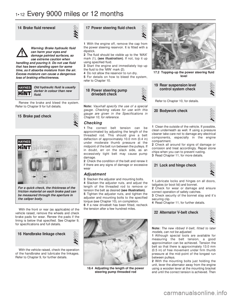
17Power steering fluid check
2
1With the engine off, remove the cap from
the power steering reservoir. It is fitted with a
dipstick.
2The fluid should be visible up to the ‘MAX’
mark (1), (see illustration). If not, top it up
using specified fluid.
3Start the engine and immediately top-up
the fluid to the ‘MIN’ mark (2).
4Do not allow the reservoir to run dry.
5For details on how to bleed the system,
refer to Chapter 10.
18Power steering pump
drivebelt check
2
Note:Vauxhall specify the use of a special
gauge. Checking values for use with this
gauge are given in the Specifications in
Chapter 10, for reference.
Checking
1The correct belt tension can be
approximated by adjusting the length of the
threaded rod. This should give a belt
deflection of approximately 10.0 mm (0.4 in)
under moderate thumb pressure at the
midpoint of the belt run between the pulleys. If
in doubt, err on the slack side, as an
excessively tight belt may cause pump
damage.
2Check the condition of the belt and renew it
if there are any signs of damage or excessive
wear
Adjustment
3Slacken the adjuster and mounting bolts.
4Slacken the adjuster nuts, and adjust the
length of the threaded rod to remove or
tension the belt as desired (see illustration).
5Tighten the adjuster nuts, and tighten the
adjuster and mounting bolts to the specified
torque (see Chapter 10), on completion.
6If a new drivebelt has been fitted, recheck
the tension after a few hundred miles.
19Rear suspension level
control system check
2
Refer to Chapter 10, for details.
20Bodywork check
1
1Clean the outside of the vehicle. If possible,
clean underneath as well. If using a pressure
cleaner take care not to damage any electrical
components, especially in the engine
compartment.
2Check all around for signs of damage or
corrosion and treat accordingly. Repair stone
chips when you can to prevent rusting.
3Read Chapter 11, for more details.
21Lock and hinge check
2
1Lubricate locks and hinges on all doors,
tailgates (or boot lid) and bonnet.
2Check for wear or damage and ensure
correct operation of safety catches.
3Check security of the bonnet stay and it’s
securing clip.
4Read Chapter 11, for further details.
22Alternator V-belt check
2
Note:The new ribbed V-belt, fitted to later
models, can not be adjusted.
1Although special tools are available for
measuring the belt tension, a good
approximation can be achieved. Tension the
belt so that there is approximately 13.0 mm
(0.5 in) of free movement under firm thumb
pressure at the mid-point of the longest run
between pulleys.
2With the mounting bolts just holding the
unit, lever the alternator away from the engine
using a wooden lever at the mounting bracket
end until the correct tension is achieved. Then
1•12Every 9000 miles or 12 months
17.2 Topping-up the power steering fluid
level
18.4 Adjusting the length of the power
steering pump threaded rod
Warning: Brake hydraulic fluid
can harm your eyes and
damage painted surfaces, so
use extreme caution when
handling and pouring it. Do not use fluid
that has been standing open for some
time, as it absorbs moisture from the air.
Excess moisture can cause a dangerous
loss of braking effectiveness.
Old hydraulic fluid is usually
darker in colour than new
fluid.
For a quick check, the thickness of the
friction material on each brake pad can
be measured through the aperture in
the caliper body.
Page 193 of 525
48Turn the crankshaft clockwise until the
TDC marks on the camshaft sprockets are
aligned with the notches in the camshaft
cover, and check that the crankshaft pulley
TDC mark is aligned with the pointer on the
rear timing belt cover.
49Proceed as described in paragraphs 30 to
34 inclusive.
5Timing belt, with automatic
adjuster- removal, refitting
and adjustment
3
Removal
1The operations are essentially the same as
described in Section 4, except that the
tensioner pulley incorporates an automatic
adjuster that simplifies the procedure as
follows.
2To release the belt tension before removal,
unscrew the timing belt tensioner pulley
securing bolt slightly then, with a large
screwdriver (or similar tool) inserted in the slot
on the tensioner arm, turn the tensioner arm
until the timing belt is slack. Tighten the
securing bolt slightly to hold the tensioner in
this position.
Refitting
3To refit the timing belt, first ensure that the
coolant pump is correctly positioned by
checking that the lug on the coolant pump
flange is aligned with the corresponding lug
on the cylinder block. If this is not the case,
slacken the coolant pump mounting bolts
slightly and move the pump accordingly.
Tighten the bolts to the specified torque on
completion (see Chapter 3).
4Refit the timing belt as described in Section 4,
then tension it as follows.
Adjustment
5Slacken the tensioner pulley securing bolt
and move the tensioner arm anti-clockwise,
until the tensioner pointer lies at its stop.
Tighten the tensioner pulley securing bolt to
hold the tensioner in this position.
6Turn the crankshaft through two complete
revolutions in the normal direction of rotation
and check that with the crankshaft pulley TDC
mark aligned with the pointer on the rear
timing belt cover, the TDC marks on the
camshaft sprockets are still aligned with the
notches in the camshaft cover.
7Slacken the tensioner pulley securing bolt
once again and move the tensioner arm
clockwise, until the tensioner pointer is
aligned with the notch in the tensioner. In the
first few hours of operation a new belt will be
subjected to ‘settling-in’, (known as the
running-in procedure). If you are refitting a
used belt (one that has been ‘run-in’), align the
pointer to approximately 4 mm to the left of
the notch, refer to Section 14 in Chapter 2A.
Tighten the tensioner pulley securing bolt
securely. Turn the crankshaft through onecomplete revolution in the normal direction of
rotation and check that the crankshaft and
camshaft timing marks still align, then refit the
remainder of the components as described in
Section 4.
8With the timing belt adjustment set in this
way, correct tension will always be maintained
by the automatic tensioner and no further
checking or adjustment will be necessary.
6Camshaft front oil seal-
removal and refitting
3
Note: A new timing belt should be used on
refitting
Removal
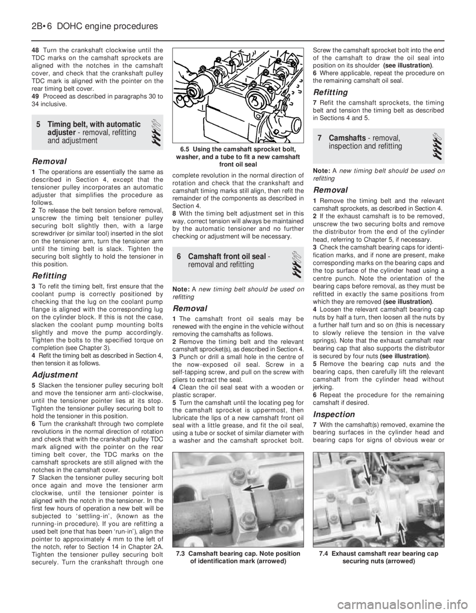
1The camshaft front oil seals may be
renewed with the engine in the vehicle without
removing the camshafts as follows.
2Remove the timing belt and the relevant
camshaft sprocket(s), as described in Section 4.
3Punch or drill a small hole in the centre of
the now-exposed oil seal. Screw in a
self-tapping screw, and pull on the screw with
pliers to extract the seal.
4Clean the oil seal seat with a wooden or
plastic scraper.
5Turn the camshaft until the locating peg for
the camshaft sprocket is uppermost, then
lubricate the lips of a new camshaft front oil
seal with a little grease, and fit the oil seal,
using a tube or socket of similar diameter with
a washer and the camshaft sprocket bolt.Screw the camshaft sprocket bolt into the end
of the camshaft to draw the oil seal into
position on its shoulder (see illustration).
6Where applicable, repeat the procedure on
the remaining camshaft oil seal.
Refitting
7Refit the camshaft sprockets, the timing
belt and tension the timing belt as described
in Sections 4 and 5.
7Camshafts- removal,
inspection and refitting
4
Note: A new timing belt should be used on
refitting
Removal
1Remove the timing belt and the relevant
camshaft sprockets, as described in Section 4.
2If the exhaust camshaft is to be removed,
unscrew the two securing bolts and remove
the distributor from the end of the cylinder
head, referring to Chapter 5, if necessary.
3Check the camshaft bearing caps for identi-
fication marks, and if none are present, make
corresponding marks on the bearing caps and
the top surface of the cylinder head using a
centre punch. Note the orientation of the
bearing caps before removal, as they must be
refitted in exactly the same positions from
which they are removed (see illustration).
4Loosen the relevant camshaft bearing cap
nuts by half a turn, then loosen all the nuts by
a further half turn and so on (this is necessary
to slowly relieve the tension in the valve
springs). Note that the exhaust camshaft rear
bearing cap that also supports the distributor
is secured by four nuts (see illustration).
5Remove the bearing cap nuts and the
bearing caps, then carefully lift the relevant
camshaft from the cylinder head without
jerking.
6Repeat the procedure for the remaining
camshaft if desired.
Inspection
7With the camshaft(s) removed, examine the
bearing surfaces in the cylinder head and
bearing caps for signs of obvious wear or
2B•6DOHC engine procedures
6.5 Using the camshaft sprocket bolt,
washer, and a tube to fit a new camshaft
front oil seal
7.4 Exhaust camshaft rear bearing cap
securing nuts (arrowed)7.3 Camshaft bearing cap. Note position
of identification mark (arrowed)
Page 205 of 525
the cylinder head above the camshaft(s)
through a hose. From here the gases are
drawn into the inlet manifold/throttle body (as
applicable) and/or the air box on the
carburettor (where applicable), where they are
re-burnt with fresh air/fuel mixture, hence
reducing harmful exhaust emissions.
Maintenance
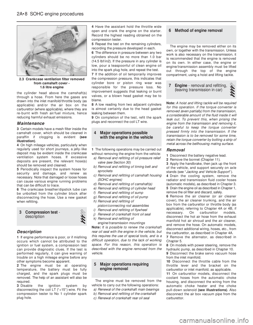
3Certain models have a mesh filter inside the
camshaft cover, which should be cleaned in
paraffin if clogging is evident (see
illustration).
4On high mileage vehicles, particularly when
regularly used for short journeys, a jelly-like
deposit may be evident inside the crankcase
ventilation system hoses. If excessive
deposits are present, the relevant hose(s)
should be removed and cleaned.
5Periodically inspect the system hoses for
security and damage, and renew as
necessary. Note that damaged or loose hoses
can cause various engine running problems
that can be difficult to trace.
6The crankcase breather/dipstick tube can
be unbolted from the cylinder block after
disconnecting the hose. Use a new gasket
when refitting.
3Compression test -
description
3
Description
1If engine performance is poor, or if misfiring
occurs which cannot be attributed to the
ignition or fuel system, a compression test
can provide diagnostic clues. If the test is
performed regularly, it can give warning of
trouble on a high mileage engine before any
other symptoms become apparent.
2The engine must be at operating
temperature, the battery must be fully
charged, and the spark plugs must be
removed. The help of an assistant will also be
required.
3Disable the ignition system by
disconnecting the coil LT (“+15”) wire. Fit the
compression tester to No 1 cylinder spark
plug hole.4Have the assistant hold the throttle wide
open and crank the engine on the starter.
Record the highest reading obtained on the
compression tester.
5Repeat the test on the remaining cylinders,
recording the pressure developed in each.
6The difference in pressure between any two
cylinders should be no more than 1.0 bar
(14.5 lbf/in2). If the pressure in any cylinder is
low, pour a teaspoonful of clean engine oil
into the spark plug hole, and repeat the test.
7If the addition of oil temporarily improves
the compression pressure, this indicates that
cylinder bore or piston ring wear was
responsible for the pressure loss. No
improvement suggests that leaking or burnt
valves, or a blown head gasket may be to
blame.
8A low reading from two adjacent cylinders
is almost certainly due to the head gasket
leaking between them.
9On completion of the test, refit the spark
plugs and reconnect the coil LT wire.
4Major operations possible
with the engine in the vehicle
1The following operations may be carried out
without removing the engine from the vehicle:
a)Removal and refitting of oil pressure relief
valve (see Section 30)
b)Removal and refitting of timing belt and
sprockets
c)Removal and refitting of camshaft housing
(SOHC engines)
d)Removal and refitting of camshaft(s)
e)Removal and refitting of cylinder head
f)Removal and refitting of sump
g)Removal and refitting of oil pump
h)Removal and refitting of
piston/connecting rod assemblies
i)Removal and refitting of flywheel
j)Renewal of crankshaft front oil seal
k)Removal and refitting of
engine/transmission mountings
Note: It is possible to renew the crankshaft
rear oil seal with the engine in the vehicle, but
this requires the use of special tools, and is a
difficult operation, due to the lack of working
space. For this reason, this operation is
described with the engine removed from the
vehicle.
5Major operations requiring
engine removal
The engine must be removed from the
vehicle to carry out the following operations:
a)Renewal of the crankshaft main bearings
b)Removal and refitting of the crankshaft
c)Renewal of crankshaft rear oil seal
6Method of engine removal
The engine may be removed either on its
own, or together with the transmission. Unless
work is also necessary on the transmission, it
is recommended that the engine is removed
on its own. In either case, the engine or
engine/transmission assembly must be lifted
out through the top of the engine
compartment, using a hoist and lifting tackle.
7Engine - removal and refitting,
(leaving transmission in car)
4
Note: A hoist and lifting tackle will be required
for this operation.If the torque converter is
removed (even partially) from the transmission,
a considerable amount of the fluid inside it will
leak out. To prevent this, when prising the
engine from the transmission and removing it,
be careful to keep the torque converter
pressed firmly into the transmission. If the
transmission is to be removed for some time,
retain the torque converter by bolting a strip of
metal across the bellhousing mating surface.
Removal
1Disconnect the battery negative lead.
2Remove the bonnet (Chapter 11).
3Apply the handbrake, then jack up the front
of the vehicle, and support securely on axle
stands (see “Jacking and Vehicle Support”).
4Drain the cooling system, remove the
radiator and transmission fluid cooler hoses
(automatic models), as described in Chapter 3.
5Drain the engine oil as described in Chapter 1,
remove the oil filter and discard, safely.
6Remove the air cleaner (or air cleaner
cover), the air cleaner trunking, and the air
box from the carburettor or throttle body (as
applicable), referring to Chapter 4A or 4B, if
necessary. On carburettor models,
disconnect the hot air hose from the exhaust
manifold hot air shroud and the air cleaner,
and remove the hose. On automatic models,
disconnect additional wiring, hoses, etc., from
the carburettor, as described in Chapter 4A.
7Remove the alternator, as described in
Chapter 5.
8On models with power steering, remove the
hydraulic pump, as described in Chapter 10.
9Disconnect the brake servo vacuum hose
from the inlet manifold.
10Disconnect the throttle cable from the
throttle lever and the bracket on the
carburettor or inlet manifold, as applicable.
11On carburettor models, disconnect the
coolant hoses from the automatic choke
housing, and disconnect the wiring from the
automatic choke heater and the choke
pull-down solenoid (see illustrations). Also
disconnect the air box vacuum pipe from the
carburettor.
2A•8SOHC engine procedures
2.3 Crankcase ventilation filter removed
from camshaft cover -
1.6 litre engine
Page 213 of 525

32Release the securing clips and remove the
main outer timing belt cover, then unclip the
smaller outer timing belt cover from the
coolant pump.
33Turn the crankshaft through at least
quarter of a turn clockwise using a socket or
spanner on the crankshaft sprocket bolt.
34If the special gauge is available, place the
locked gauge at the centre of the belt run
between the coolant pump and the camshaft
sprocket. The gauge should locate on the
timing belt (see illustration).
35Slowly release the operating lever on the
gauge, then lightly tap the gauge two or three
times, and note the reading on the scale (see
illustration).
36If the reading is not as specified, loosen
the three coolant pump securing bolts, and
rotate the pump in the required direction to
achieve the desired reading on the gauge.
Rotate the pump clockwise to increase the
belt tension, or anti-clockwise to decrease the
tension.
37Lightly tighten the coolant pump securing
bolts.
38Remove the tensioning gauge, and turn
the crankshaft through one full turn clockwise.
39Re-check the belt tension as described in
paragraphs 4 and 5.
40If the tension is not as specified, repeat
paragraphs 6 to 9 inclusive until the desired,
consistent, reading is obtained.
41On completion of adjustment, remove the
checking gauge, tighten the coolant pump
bolts to the specified torque, and refit the
outer timing belt covers.
42If the special checking gauge is not
available, the timing belt tension can be
checked approximately by twisting the belt
between the thumb and forefinger, at the
centre of the run between the coolant pump
and the camshaft sprocket. It should just be
possible to twist the belt through 90°using
moderate pressure (see illustration). If
adjustment is necessary, continue as
described previously in this Section, but have
the belt tension checked by a Vauxhall dealer
using the special gauge at the earliest
opportunity. If in doubt, err on the tight side
when adjusting the tension, as if the belt is too
slack, it may jump on the sprockets, which
could result in serious engine damage.12Timing belt and tensioner 1.4
and 1.6 models (not C16 NZ2) -
removal, refitting and adjustment
3
Removal
1Remove the timing belt outer covers as
described in Section 11, paragraphs 1 to 5.
2To lock the tensioner in its slackest position
for removal and refitting, move the tensioner
indicator arm clockwise until the holes align in
the baseplate and the arm. Then insert a
close-fitting pin, such as a drift, to retain them
(see illustration). The tensioner can then be
unbolted, or the belt can be removed.
3Check that the tensioner roller rotates
smoothly and easily, with no noises or signs
of free play, roughness or notchy movement.
Check also that there is no sign of physical
wear or damage. If the tensioner is faulty in
any way, or if there is any reason to doubt the
continued efficiency of its spring, the
complete assembly must be renewed.
Refitting
4On refitting, ensure that the tensioner
baseplate lug engages with the hole in the oil
pump housing, then tighten the tensioner bolt
securely and remove the locking pin; the
tensioner should be quite free to move.
5Set the belt tension as described below.
Adjustment
6Whenever the timing belt is disturbed,
whether during belt renewal or any otherengine overhaul work, its tension must be set
on assembly - note that this procedure must
only be carried out on a cold engine.
7It is assumed that the belt has been
removed and refitted, i.e. that the crankshaft
pulley and timing belt outer covers are
removed, that the tensioner is unlocked (see
above) and that No 1 cylinder is in its firing
position (just before TDC on the compression
stroke). Temporarily refit the crankshaft pulley
bolt and remove the spark plugs so that the
crankshaft can be rotated easily.
8Note also that turning the coolant pump
with the precision required is a great deal
easier if a special spanner (Kent-Moore Part
No KM-421-A) is used. Alternatives are
available from manufacturers such as
Sykes-Pickavant (Part No 031300) (see
illustration).
9With the belt refitted and correctly routed
(see Section 11), ensure that the punch mark
on the crankshaft sprocket and the stamped
line on the camshaft sprocket are aligned with
their respective timing belt rear cover notches
(see illustrations).
10Tighten the belt by slackening its three
securing bolts, and turning the coolant pump
clockwise until the holes align in the tensioner
indicator arm and baseplate (the tensioner
indicator arm will then have moved fully
clockwise to its stop). Lightly tighten the
pump securing bolts, just sufficiently to
prevent the pump from moving.
11Using a spanner applied to the crankshaft
pulley bolt, turn the crankshaft smoothly
2A•16SOHC engine procedures
11.34 Tension blade KM-510-A correctly
positioned on timing belt. Belt must pass
through points A, B and C - SOHC engines11.42 Checking timing belt tension by
twisting belt through 90º between thumb
and forefinger
12.8 Using a special spanner to adjust the
timing belt by moving the coolant pump12.2 Using a close-fitting drift to lock the
tensioner. Note baseplate lug engaged in
oil pump housing (arrowed)
11.35 Note the reading on the scale of the
tension gauge -
1.6 litre engine
Page 214 of 525

(without jerking it or the belt may jump a
tooth), through 2 complete revolutions (720°)
clockwise, until the camshaft and crankshaft
sprocket timing marks are once again aligned
as described in paragraph 13. The position of
the coolant pump must not alter.
12Slacken the timing belt by turning the
coolant pump anti-clockwise until the
tensioner’s indicator pointer is in the centre of
its baseplate notch; the timing belt tension is
then correct (see illustration). Tighten the
coolant pump bolts to the specified torque
wrench setting (see Chapter 3), then turn the
crankshaft through two further turns
clockwise and recheck the setting.
13If the pointer and notch are not aligned,
the operation must be repeated from
paragraph 7. On completion, refit all
components removed.
13Timing belt cover aperture,
1.4 and 1.6 models - general
General
The rear timing belt cover fitted to 1991 and
1992 model year 1.4 and 1.6 litre engines,
incorporates a small aperture just above the
oil pump housing. In certain circumstances, it
is possible for foreign objects, such as gravel,
to penetrate through this aperture and cause
the timing belt to jump a tooth on its
sprockets. For this reason, it is desirable to
cover the aperture to prevent the possibility of
this occurrence. A modified cover without an
aperture was introduced for 1993 models.
A piece of suitably moulded sponge rubber
(P/N 90469594), is available from Vauxhall
dealers to enable the aperture to be covered.
On models without power steering, the
sponge rubber can be inserted into the cover
aperture from above. If power steering is
fitted, the sponge rubber is inserted into place
from below. If access is difficult, particularly if
the drivebelt is of the ribbed V-belt type, it
may be easier to remove the alternator/power
steering pump drivebelt as described in
Chapter 5. Refit, and where applicable adjust,
the belt tension on completion.
14Timing belt and tensioner C16
NZ2, 1.8 and 2.0 litre - removal,
refitting and adjustment
3
Removal
1An alternative type of spring loaded
automatic timing belt tensioner is fitted to
these engines, from 1993 onward (see
illustration). The tensioner assembly is similar
to other automatic tensioners, but the removal
and refitting procedures vary as follows.
2The timing belt main outer cover may be
secured either by clips or by hexagon-headed
screws to the rear cover; in some cases, a
combination of clips and screws may be used.
3To release the belt tension before removal,
unscrew the timing belt tensioner securing
bolt slightly then, with a tool inserted in the
slot on the tensioner arm, turn the tensioner
arm until the timing belt is slack. If necessary,remove completely and examine the tensioner
as described in Section 12.
Refitting
4Refit the tensioner into position and tighten
the securing bolt slightly.
5Ensure that the coolant pump is correctly
positioned by checking that the lug on the
coolant pump flange is aligned with the
corresponding lug on the cylinder block. If this
is not the case, slacken the coolant pump
mounting bolts slightly and move the pump
accordingly (see Chapter 3). Tighten the bolts
to the specified torque on completion.
6Refit the timing belt then tension it as
follows.
Adjustment
7Slacken the automatic tensioner securing
bolt and move the tensioner arm anti-
clockwise, until the tensioner pointer lies at its
stop. Tighten the tensioner securing bolt to
hold the tensioner in this position.
SOHC engine procedures 2A•17
12.12 Timing belt tension is correct when
the tensioner indicator pointer aligns with
the centre of the baseplate notch12.9B . . . and stamped line (A) on
camshaft sprocket with timing belt rear
cover notch (B)12.9A Align punch mark (A) on crankshaft
sprocket with timing belt rear
cover notch (B) . . .
2A
14.1 Timing belt automatic tensioner details (alternative type)
A Alignment lugs on coolant pump and cylinder block
B Tensioner pointer aligned with notch in tensioner bracket
1 Move the tensioner arm anti-clockwise to release the belt tension
2 Move the tensioner arm clockwise to tension the belt