1988 OPEL CALIBRA fuel pump
[x] Cancel search: fuel pumpPage 175 of 525
1•4Maintenance schedule
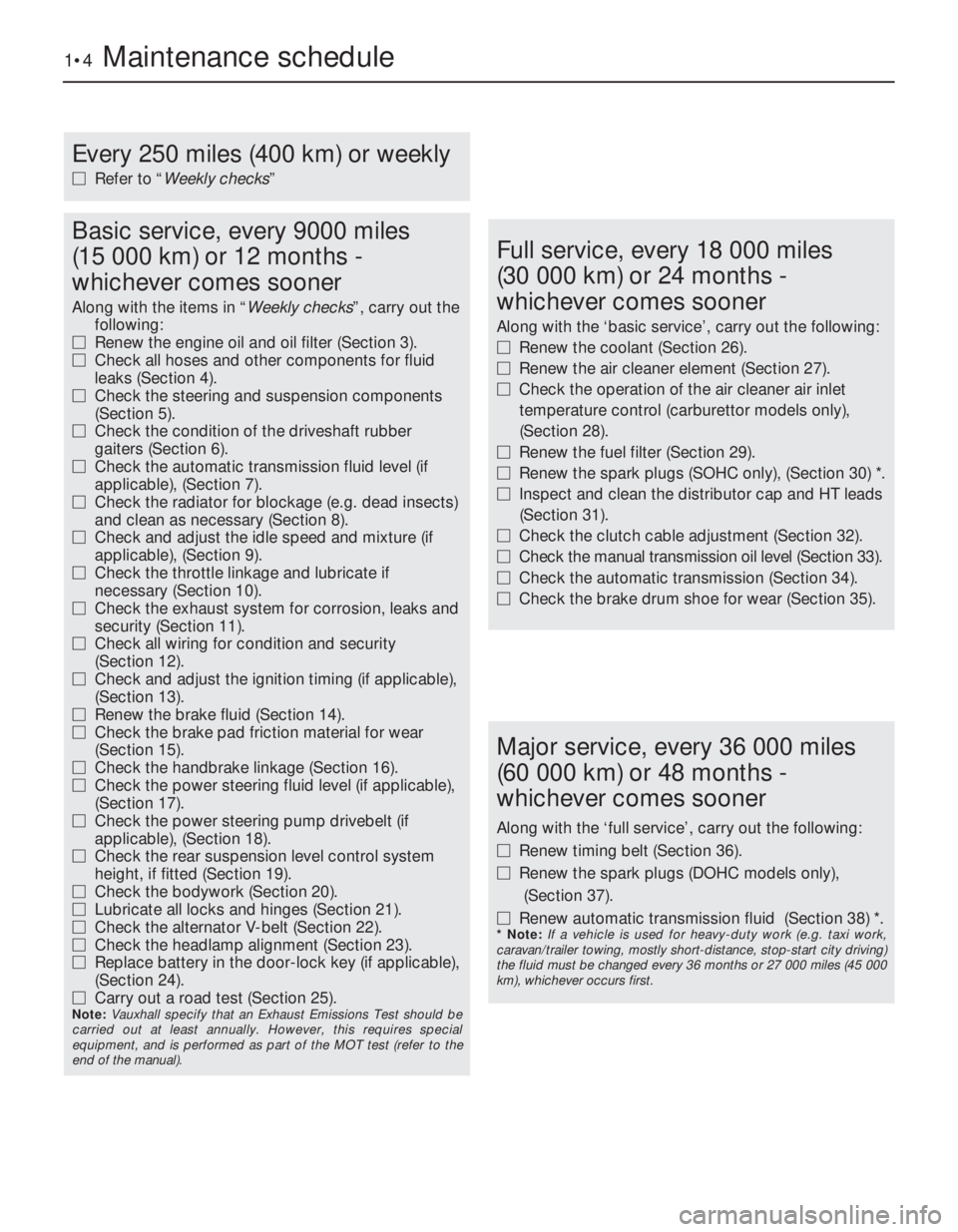
Every 250 miles (400 km) or weekly
MRefer to “Weekly checks”
Basic service, every 9000 miles
(15 000 km) or 12 months -
whichever comes sooner
Along with the items in “Weekly checks”, carry out the
following:
MRenew the engine oil and oil filter (Section 3).
MCheck all hoses and other components for fluid
leaks (Section 4).
MCheck the steering and suspension components
(Section 5).
MCheck the condition of the driveshaft rubber
gaiters (Section 6).
MCheck the automatic transmission fluid level (if
applicable), (Section 7).
MCheck the radiator for blockage (e.g. dead insects)
and clean as necessary (Section 8).
MCheck and adjust the idle speed and mixture (if
applicable), (Section 9).
MCheck the throttle linkage and lubricate if
necessary (Section 10).
MCheck the exhaust system for corrosion, leaks and
security (Section 11).
MCheck all wiring for condition and security
(Section 12).
MCheck and adjust the ignition timing (if applicable),
(Section 13).
MRenew the brake fluid (Section 14).
MCheck the brake pad friction material for wear
(Section 15).
MCheck the handbrake linkage (Section 16).
MCheck the power steering fluid level (if applicable),
(Section 17).
MCheck the power steering pump drivebelt (if
applicable), (Section 18).
MCheck the rear suspension level control system
height, if fitted (Section 19).
MCheck the bodywork (Section 20).
MLubricate all locks and hinges (Section 21).
MCheck the alternator V-belt (Section 22).
MCheck the headlamp alignment (Section 23).
MReplace battery in the door-lock key (if applicable),
(Section 24).
MCarry out a road test (Section 25).
Note: Vauxhall specify that an Exhaust Emissions Test should be
carried out at least annually. However, this requires special
equipment, and is performed as part of the MOT test (refer to the
end of the manual).
Full service, every 18 000 miles
(30 000 km) or 24 months -
whichever comes sooner
Along with the ‘basic service’, carry out the following:
MRenew the coolant (Section 26).
MRenew the air cleaner element (Section 27).
MCheck the operation of the air cleaner air inlet
temperature control (carburettor models only),
(Section 28).
MRenew the fuel filter (Section 29).
MRenew the spark plugs (SOHC only), (Section 30) *.
MInspect and clean the distributor cap and HT leads
(Section 31).
MCheck the clutch cable adjustment (Section 32).
MCheck the manual transmission oil level (Section 33).
MCheck the automatic transmission (Section 34).
MCheck the brake drum shoe for wear (Section 35).
Major service, every 36 000 miles
(60 000 km) or 48 months -
whichever comes sooner
Along with the ‘full service’, carry out the following:
MRenew timing belt (Section 36).
MRenew the spark plugs (DOHC models only),
(Section 37).
MRenew automatic transmission fluid (Section 38) *.
* Note: If a vehicle is used for heavy-duty work (e.g. taxi work,
caravan/trailer towing, mostly short-distance, stop-start city driving)
the fluid must be changed every 36 months or 27 000 miles (45 000
km), whichever occurs first.
Page 176 of 525
Maintenance - component location 1•5
1
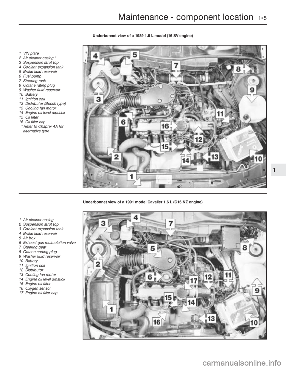
Underbonnet view of a 1989 1.6 L model (16 SV engine)
1 VIN plate
2 Air cleaner casing *
3 Suspension strut top
4 Coolant expansion tank
5 Brake fluid reservoir
6 Fuel pump
7 Steering rack
8 Octane rating plug
9 Washer fluid reservoir
10 Battery
11 Ignition coil
12 Distributor (Bosch type)
13 Cooling fan motor
14 Engine oil level dipstick
15 Oil filter
16 Oil filler cap
* Refer to Chapter 4A for
alternative type
Underbonnet view of a 1991 model Cavalier 1.6 L (C16 NZ engine)
1 Air cleaner casing
2 Suspension strut top
3 Coolant expansion tank
4 Brake fluid reservoir
5 Air box
6 Exhaust gas recirculation valve
7 Steering gear
8 Octane coding plug
9 Washer fluid reservoir
10 Battery
11 Ignition coil
12 Distributor
13 Cooling fan motor
14 Engine oil level dipstick
15 Engine oil filter
16 Oxygen sensor
17 Engine oil filler cap
Page 179 of 525

1Introduction
This Chapter is designed to help the home
mechanic maintain his/her vehicle for safety,
economy, long life and peak performance.
The Chapter contains a master maintenance
schedule, followed by Sections dealing specifically
with each task in the schedule. Visual checks,
adjustments, component renewal and other helpful
items are included. Refer to the accompanying
illustrations of the engine compartment and the
underside of the vehicle for the locations of the
various components.
Servicing your vehicle according to the
mileage/time maintenance schedule and the
following Sections will provide a planned
maintenance programme, which should result in a
long and reliable service life. This is a comprehensiveplan, so maintaining some items but not others at
the specified service intervals, will not produce the
same results.
As you service your vehicle, you will
discover that many of the procedures can -
and should - be grouped together, because of
the particular procedure being performed, or
because of the proximity of two otherwise-
unrelated components to one another. For
example, if the vehicle is raised for any
reason, the exhaust can be inspected at the
same time as the suspension and steering
components.
The first step in this maintenance
programme is to prepare yourself before the
actual work begins. Read through all the
Sections relevant to the work to be carried
out, then make a list and gather all the parts
and tools required. If a problem is found, seek
advice from a parts specialist, or a dealer
service department.
2Intensive maintenance
If, from the time the vehicle is new, routine
maintenance schedule is followed closely,
frequent checks made of fluid levels and high-
wear items, as recommended, the engine will
be kept in relatively good running condition.
The need for additional work will be minimised
It is possible that there will be times when
the engine is running poorly due to the lack of
regular maintenance. This is even more likely
if a used vehicle, which has not received
regular and frequent maintenance checks, is
purchased. In such cases, additional work
may need to be carried out, outside of the
regular maintenance intervals.
If engine wear is suspected, a compression
1•8Maintenance - component location
Rear underbody view of a 1990 GSi 2000 model (fully independent rear suspension)
1 Fuel tank securing strap
2 Shock absorber
3 ABS wheel sensor
4 Semi-trailing arm
5 Suspension crossmember
mounting bracing bracket
6 Handbrake cable
7 Suspension crossmember
8 Exhaust expansion box
9 Fuel pump
Maintenance procedures
Page 190 of 525
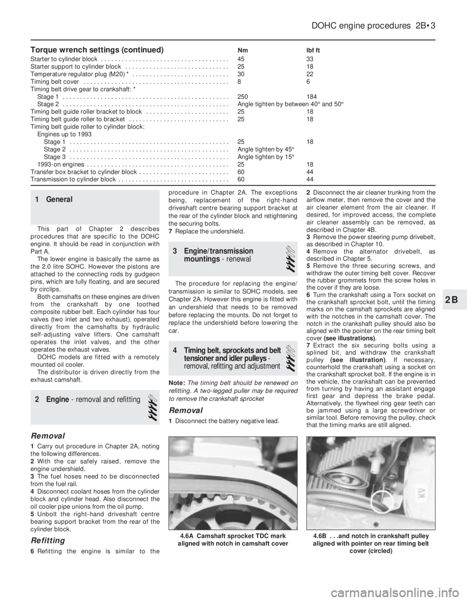
Torque wrench settings (continued)Nmlbf ft
Starter to cylinder block . . . . . . . . . . . . . . . . . . . . . . . . . . . . . . . . . . . . .4533
Starter support to cylinder block . . . . . . . . . . . . . . . . . . . . . . . . . . . . . .2518
Temperature regulator plug (M20) * . . . . . . . . . . . . . . . . . . . . . . . . . . . .3022
Timing belt cover . . . . . . . . . . . . . . . . . . . . . . . . . . . . . . . . . . . . . . . . . .86
Timing belt drive gear to crankshaft: *
Stage 1 . . . . . . . . . . . . . . . . . . . . . . . . . . . . . . . . . . . . . . . . . . . . . . . .250184
Stage 2 . . . . . . . . . . . . . . . . . . . . . . . . . . . . . . . . . . . . . . . . . . . . . . . .Angle tighten by between 40°and 50°
Timing belt guide roller bracket to block . . . . . . . . . . . . . . . . . . . . . . . .2518
Timing belt guide roller to bracket . . . . . . . . . . . . . . . . . . . . . . . . . . . . .2518
Timing belt guide roller to cylinder block:
Engines up to 1993
Stage 1 . . . . . . . . . . . . . . . . . . . . . . . . . . . . . . . . . . . . . . . . . . . . . .2518
Stage 2 . . . . . . . . . . . . . . . . . . . . . . . . . . . . . . . . . . . . . . . . . . . . . .Angle tighten by 45°
Stage 3 . . . . . . . . . . . . . . . . . . . . . . . . . . . . . . . . . . . . . . . . . . . . . .Angle tighten by 15°
1993-on engines . . . . . . . . . . . . . . . . . . . . . . . . . . . . . . . . . . . . . . . . .2518
Transfer box bracket to cylinder block . . . . . . . . . . . . . . . . . . . . . . . . . .6044
Transmission to cylinder block . . . . . . . . . . . . . . . . . . . . . . . . . . . . . . . .6044
1General
This part of Chapter 2 describes
procedures that are specific to the DOHC
engine. It should be read in conjunction with
Part A.
The lower engine is basically the same as
the 2.0 litre SOHC. However the pistons are
attached to the connecting rods by gudgeon
pins, which are fully floating, and are secured
by circlips.
Both camshafts on these engines are driven
from the crankshaft by one toothed
composite rubber belt. Each cylinder has four
valves (two inlet and two exhaust), operated
directly from the camshafts by hydraulic
self-adjusting valve lifters. One camshaft
operates the inlet valves, and the other
operates the exhaust valves.
DOHC models are fitted with a remotely
mounted oil cooler.
The distributor is driven directly from the
exhaust camshaft.
2Engine - removal and refitting
4
Removal
1Carry out procedure in Chapter 2A, noting
the following differences.
2With the car safely raised, remove the
engine undershield.
3The fuel hoses need to be disconnected
from the fuel rail.
4Disconnect coolant hoses from the cylinder
block and cylinder head. Also disconnect the
oil cooler pipe unions from the oil pump.
5Unbolt the right-hand driveshaft centre
bearing support bracket from the rear of the
cylinder block.
Refitting
6Refitting the engine is similar to theprocedure in Chapter 2A. The exceptions
being, replacement of the right-hand
driveshaft centre bearing support bracket at
the rear of the cylinder block and retightening
the securing bolts.
7Replace the undershield.
3Engine/transmission
mountings- renewal
3
The procedure for replacing the engine/
transmission is similar to SOHC models, see
Chapter 2A. However this engine is fitted with
an undershield that needs to be removed
before replacing the mounts. Do not forget to
replace the undershield before lowering the
car.
4Timing belt, sprockets and belt
tensioner and idler pulleys-
removal, refitting and adjustment
3
Note: The timing belt should be renewed on
refitting. A two-legged puller may be required
to remove the crankshaft sprocket
Removal
1Disconnect the battery negative lead.2Disconnect the air cleaner trunking from the
airflow meter, then remove the cover and the
air cleaner element from the air cleaner. If
desired, for improved access, the complete
air cleaner assembly can be removed, as
described in Chapter 4B.
3Remove the power steering pump drivebelt,
as described in Chapter 10.
4Remove the alternator drivebelt, as
described in Chapter 5.
5Remove the three securing screws, and
withdraw the outer timing belt cover. Recover
the rubber grommets from the screw holes in
the cover if they are loose.
6Turn the crankshaft using a Torx socket on
the crankshaft sprocket bolt, until the timing
marks on the camshaft sprockets are aligned
with the notches in the camshaft cover. The
notch in the crankshaft pulley should also be
aligned with the pointer on the rear timing belt
cover (see illustrations).
7Extract the six securing bolts using a
splined bit, and withdraw the crankshaft
pulley (see illustration). If necessary,
counterhold the crankshaft using a socket on
the crankshaft sprocket bolt. If the engine is in
the vehicle, the crankshaft can be prevented
from turning by having an assistant engage
first gear and depress the brake pedal.
Alternatively, the flywheel ring gear teeth can
be jammed using a large screwdriver or
similar tool. Before removing the pulley, check
that the timing marks are still aligned.
DOHC engine procedures 2B•3
4.6B . . .and notch in crankshaft pulley
aligned with pointer on rear timing belt
cover (circled)4.6A Camshaft sprocket TDC mark
aligned with notch in camshaft cover
2B
Page 203 of 525
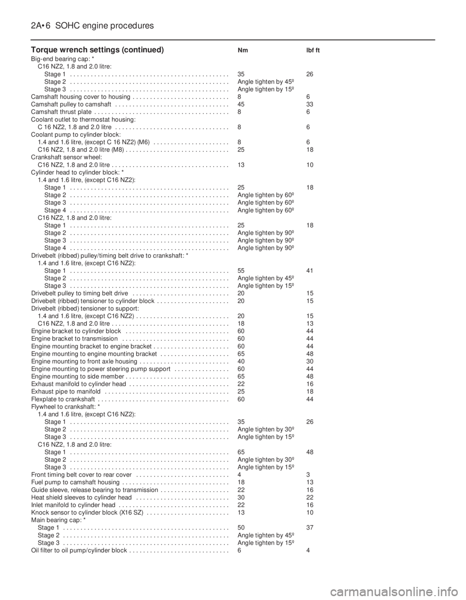
Torque wrench settings (continued)Nmlbf ft
Big-end bearing cap: *
C16 NZ2, 1.8 and 2.0 litre:
Stage 1 . . . . . . . . . . . . . . . . . . . . . . . . . . . . . . . . . . . . . . . . . . . . . .3526
Stage 2 . . . . . . . . . . . . . . . . . . . . . . . . . . . . . . . . . . . . . . . . . . . . . .Angle tighten by 45º
Stage 3 . . . . . . . . . . . . . . . . . . . . . . . . . . . . . . . . . . . . . . . . . . . . . .Angle tighten by 15º
Camshaft housing cover to housing . . . . . . . . . . . . . . . . . . . . . . . . . . . .86
Camshaft pulley to camshaft . . . . . . . . . . . . . . . . . . . . . . . . . . . . . . . . .4533
Camshaft thrust plate . . . . . . . . . . . . . . . . . . . . . . . . . . . . . . . . . . . . . . .86
Coolant outlet to thermostat housing:
C 16 NZ2, 1.8 and 2.0 litre . . . . . . . . . . . . . . . . . . . . . . . . . . . . . . . . .86
Coolant pump to cylinder block:
1.4 and 1.6 litre, (except C 16 NZ2) (M6) . . . . . . . . . . . . . . . . . . . . . .86
C16 NZ2, 1.8 and 2.0 litre (M8) . . . . . . . . . . . . . . . . . . . . . . . . . . . . . .2518
Crankshaft sensor wheel:
C16 NZ2, 1.8 and 2.0 litre . . . . . . . . . . . . . . . . . . . . . . . . . . . . . . . . . .1310
Cylinder head to cylinder block: *
1.4 and 1.6 litre, (except C16 NZ2):
Stage 1 . . . . . . . . . . . . . . . . . . . . . . . . . . . . . . . . . . . . . . . . . . . . . .2518
Stage 2 . . . . . . . . . . . . . . . . . . . . . . . . . . . . . . . . . . . . . . . . . . . . . .Angle tighten by 60º
Stage 3 . . . . . . . . . . . . . . . . . . . . . . . . . . . . . . . . . . . . . . . . . . . . . .Angle tighten by 60º
Stage 4 . . . . . . . . . . . . . . . . . . . . . . . . . . . . . . . . . . . . . . . . . . . . . .Angle tighten by 60º
C16 NZ2, 1.8 and 2.0 litre:
Stage 1 . . . . . . . . . . . . . . . . . . . . . . . . . . . . . . . . . . . . . . . . . . . . . .2518
Stage 2 . . . . . . . . . . . . . . . . . . . . . . . . . . . . . . . . . . . . . . . . . . . . . .Angle tighten by 90º
Stage 3 . . . . . . . . . . . . . . . . . . . . . . . . . . . . . . . . . . . . . . . . . . . . . .Angle tighten by 90º
Stage 4 . . . . . . . . . . . . . . . . . . . . . . . . . . . . . . . . . . . . . . . . . . . . . .Angle tighten by 90º
Drivebelt (ribbed) pulley/timing belt drive to crankshaft: *
1.4 and 1.6 litre, (except C16 NZ2):
Stage 1 . . . . . . . . . . . . . . . . . . . . . . . . . . . . . . . . . . . . . . . . . . . . . .5541
Stage 2 . . . . . . . . . . . . . . . . . . . . . . . . . . . . . . . . . . . . . . . . . . . . . .Angle tighten by 45º
Stage 3 . . . . . . . . . . . . . . . . . . . . . . . . . . . . . . . . . . . . . . . . . . . . . .Angle tighten by 15º
Drivebelt pulley to timing belt drive . . . . . . . . . . . . . . . . . . . . . . . . . . . .2015
Drivebelt (ribbed) tensioner to cylinder block . . . . . . . . . . . . . . . . . . . . .2015
Drivebelt (ribbed) tensioner to support:
1.4 and 1.6 litre, (except C16 NZ2) . . . . . . . . . . . . . . . . . . . . . . . . . . .2015
C16 NZ2, 1.8 and 2.0 litre . . . . . . . . . . . . . . . . . . . . . . . . . . . . . . . . . .1813
Engine bracket to cylinder block . . . . . . . . . . . . . . . . . . . . . . . . . . . . . .6044
Engine bracket to transmission . . . . . . . . . . . . . . . . . . . . . . . . . . . . . . .6044
Engine mounting bracket to engine bracket . . . . . . . . . . . . . . . . . . . . . .6044
Engine mounting to engine mounting bracket . . . . . . . . . . . . . . . . . . . .6548
Engine mounting to front axle housing . . . . . . . . . . . . . . . . . . . . . . . . . .4030
Engine mounting to power steering pump support . . . . . . . . . . . . . . . .6044
Engine mounting to side member . . . . . . . . . . . . . . . . . . . . . . . . . . . . . .6548
Exhaust manifold to cylinder head . . . . . . . . . . . . . . . . . . . . . . . . . . . . .2216
Exhaust pipe to manifold . . . . . . . . . . . . . . . . . . . . . . . . . . . . . . . . . . . .2518
Flexplate to crankshaft . . . . . . . . . . . . . . . . . . . . . . . . . . . . . . . . . . . . . .6044
Flywheel to crankshaft: *
1.4 and 1.6 litre, (except C16 NZ2):
Stage 1 . . . . . . . . . . . . . . . . . . . . . . . . . . . . . . . . . . . . . . . . . . . . . .3526
Stage 2 . . . . . . . . . . . . . . . . . . . . . . . . . . . . . . . . . . . . . . . . . . . . . .Angle tighten by 30º
Stage 3 . . . . . . . . . . . . . . . . . . . . . . . . . . . . . . . . . . . . . . . . . . . . . .Angle tighten by 15º
C16 NZ2, 1.8 and 2.0 litre:
Stage 1 . . . . . . . . . . . . . . . . . . . . . . . . . . . . . . . . . . . . . . . . . . . . . .6548
Stage 2 . . . . . . . . . . . . . . . . . . . . . . . . . . . . . . . . . . . . . . . . . . . . . .Angle tighten by 30º
Stage 3 . . . . . . . . . . . . . . . . . . . . . . . . . . . . . . . . . . . . . . . . . . . . . .Angle tighten by 15º
Front timing belt cover to rear cover . . . . . . . . . . . . . . . . . . . . . . . . . . .43
Fuel pump to camshaft housing . . . . . . . . . . . . . . . . . . . . . . . . . . . . . . .1813
Guide sleeve, release bearing to transmission . . . . . . . . . . . . . . . . . . . .2216
Heat shield sleeves to cylinder head . . . . . . . . . . . . . . . . . . . . . . . . . . .3022
Inlet manifold to cylinder head . . . . . . . . . . . . . . . . . . . . . . . . . . . . . . . .2216
Knock sensor to cylinder block (X16 SZ) . . . . . . . . . . . . . . . . . . . . . . . .1310
Main bearing cap: *
Stage 1 . . . . . . . . . . . . . . . . . . . . . . . . . . . . . . . . . . . . . . . . . . . . . . . .5037
Stage 2 . . . . . . . . . . . . . . . . . . . . . . . . . . . . . . . . . . . . . . . . . . . . . . . .Angle tighten by 45º
Stage 3 . . . . . . . . . . . . . . . . . . . . . . . . . . . . . . . . . . . . . . . . . . . . . . . .Angle tighten by 15º
Oil filter to oil pump/cylinder block . . . . . . . . . . . . . . . . . . . . . . . . . . . . .64
2A•6SOHC engine procedures
Page 204 of 525
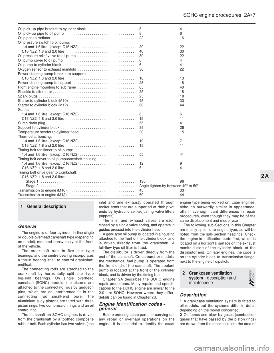
Oil pick-up pipe bracket to cylinder block . . . . . . . . . . . . . . . . . . . . . . .64
Oil pick-up pipe to oil pump . . . . . . . . . . . . . . . . . . . . . . . . . . . . . . . . . .86
Oil pipes to radiator . . . . . . . . . . . . . . . . . . . . . . . . . . . . . . . . . . . . . . . .2216
Oil pressure switch to oil pump:
1.4 and 1.6 litre, (except C16 NZ2) . . . . . . . . . . . . . . . . . . . . . . . . . .3022
C16 NZ2, 1.8 and 2.0 litre . . . . . . . . . . . . . . . . . . . . . . . . . . . . . . . . . .4030
Oil pressure relief valve to oil pump . . . . . . . . . . . . . . . . . . . . . . . . . . . .3022
Oil pump cover to oil pump . . . . . . . . . . . . . . . . . . . . . . . . . . . . . . . . . .64
Oil pump to cylinder block . . . . . . . . . . . . . . . . . . . . . . . . . . . . . . . . . . .64
Oxygen sensor to exhaust manifold . . . . . . . . . . . . . . . . . . . . . . . . . . . .3022
Power steering pump bracket to support:
C16 NZ2, 1.8 and 2.0 litre . . . . . . . . . . . . . . . . . . . . . . . . . . . . . . . . . .1813
Power steering pump to support . . . . . . . . . . . . . . . . . . . . . . . . . . . . . .2518
Right engine mounting to subframe . . . . . . . . . . . . . . . . . . . . . . . . . . . .6548
Shackle to alternator . . . . . . . . . . . . . . . . . . . . . . . . . . . . . . . . . . . . . . . .2518
Spark plugs . . . . . . . . . . . . . . . . . . . . . . . . . . . . . . . . . . . . . . . . . . . . . . .2518
Starter to cylinder block (M10) . . . . . . . . . . . . . . . . . . . . . . . . . . . . . . . .4533
Starter to cylinder block (M12) . . . . . . . . . . . . . . . . . . . . . . . . . . . . . . . .6044
Sump:
1.4 and 1.6 litre, (except C16 NZ2) . . . . . . . . . . . . . . . . . . . . . . . . . . .86
C16 NZ2, 1.8 and 2.0 litre . . . . . . . . . . . . . . . . . . . . . . . . . . . . . . . . . .1511
Sump drain plug . . . . . . . . . . . . . . . . . . . . . . . . . . . . . . . . . . . . . . . . . . .5541
Support to cylinder block . . . . . . . . . . . . . . . . . . . . . . . . . . . . . . . . . . . .3526
Temperature sender to cylinder head . . . . . . . . . . . . . . . . . . . . . . . . . . .2015
Thermostat housing:
1.4 and 1.6 litre, (except C16 NZ2) . . . . . . . . . . . . . . . . . . . . . . . . . . .107
C16 NZ2, 1.8 and 2.0 litre . . . . . . . . . . . . . . . . . . . . . . . . . . . . . . . . . .1511
Timing belt tensioner to oil pump:
1.4 and 1.6 litre, (except C16 NZ2) . . . . . . . . . . . . . . . . . . . . . . . . . . .5541
Timing belt cover to oil pump/camshaft housing:
1.4 and 1.6 litre, (except C16 NZ2) . . . . . . . . . . . . . . . . . . . . . . . . . . .129
C16 NZ2, 1.8 and 2.0 litre . . . . . . . . . . . . . . . . . . . . . . . . . . . . . . . . . .64
Timing belt drive gear to crankshaft:
C16 NZ2, 1.8 and 2.0 litre:
Stage 1 . . . . . . . . . . . . . . . . . . . . . . . . . . . . . . . . . . . . . . . . . . . . . .13096
Stage 2 . . . . . . . . . . . . . . . . . . . . . . . . . . . . . . . . . . . . . . . . . . . . . .Angle tighten by between 40º to 50º
Transmission to engine (M10) . . . . . . . . . . . . . . . . . . . . . . . . . . . . . . . . .4533
Transmission to engine (M12) . . . . . . . . . . . . . . . . . . . . . . . . . . . . . . . . .6044
1General description
General
The engine is of four-cylinder, in-line single
or double overhead camshaft type (depending
on model), mounted transversely at the front
of the vehicle.
The crankshaft runs in five shell-type
bearings, and the centre bearing incorporates
a thrust bearing shell to control crankshaft
endfloat.
The connecting rods are attached to the
crankshaft by horizontally split shell-type
big-end bearings. On single overhead
camshaft (SOHC) models, the pistons are
attached to the connecting rods by gudgeon
pins, which are an interference fit in the
connecting rod small-end bore. The
aluminium alloy pistons are fitted with three
piston rings: two compression rings and an oil
control ring.
The camshaft on SOHC engines is driven
from the crankshaft by a toothed composite
rubber belt. Each cylinder has two valves (oneinlet and one exhaust), operated through
rocker arms that are supported at their pivot
ends by hydraulic self-adjusting valve lifters
(tappets).
The inlet and exhaust valves are each
closed by a single valve spring, and operate in
guides pressed into the cylinder head.
A gear-type oil pump is located in a housing
attached to the front of the cylinder block, and
is driven directly from the crankshaft. A
full-flow type oil filter is fitted.
The distributor is driven directly from the
end of the camshaft. On carburettor models,
the mechanical fuel pump is operated from
the front end of the camshaft. The coolant
pump is located at the front of the cylinder
block, and is driven by the timing belt.
Chapter 2A describes the SOHC engine
repair procedures. Many repairs and specifi-
cations to the DOHC engine are similar to the
2.0 litre SOHC. However where they differ,
details can be found in Chapter 2B.
Engine identification codes -
general
Before ordering spare parts, or carrying out
any repair or overhaul operations on the
engine, it is essential to identify the exactengine type being worked on. Later engines,
although outwardly similar in appearance,
often have significant differences in repair
procedures, even though they may be of the
same displacement and model year.
The following sub-Sections in this Chapter
are mainly specific to engine type, as will be
noted from the sub-Section headings. Check
the engine identification code first, which is
located on a horizontal surface on the exhaust
manifold side of the cylinder block, at the
distributor end. On later engines, the code is
on the cylinder block-to-transmission flange,
next to the engine oil dipstick.
2Crankcase ventilation
system - description and
maintenance
2
Description
1A crankcase ventilation system is fitted to
all models, but the systems differ in detail
depending on the model concerned.
2Oil fumes and blow-by gases (combustion
gases that have passed by the piston rings)
are drawn from the crankcase into the area of
SOHC engine procedures 2A•7
2A
Page 205 of 525
the cylinder head above the camshaft(s)
through a hose. From here the gases are
drawn into the inlet manifold/throttle body (as
applicable) and/or the air box on the
carburettor (where applicable), where they are
re-burnt with fresh air/fuel mixture, hence
reducing harmful exhaust emissions.
Maintenance
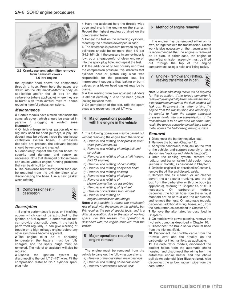
3Certain models have a mesh filter inside the
camshaft cover, which should be cleaned in
paraffin if clogging is evident (see
illustration).
4On high mileage vehicles, particularly when
regularly used for short journeys, a jelly-like
deposit may be evident inside the crankcase
ventilation system hoses. If excessive
deposits are present, the relevant hose(s)
should be removed and cleaned.
5Periodically inspect the system hoses for
security and damage, and renew as
necessary. Note that damaged or loose hoses
can cause various engine running problems
that can be difficult to trace.
6The crankcase breather/dipstick tube can
be unbolted from the cylinder block after
disconnecting the hose. Use a new gasket
when refitting.
3Compression test -
description
3
Description
1If engine performance is poor, or if misfiring
occurs which cannot be attributed to the
ignition or fuel system, a compression test
can provide diagnostic clues. If the test is
performed regularly, it can give warning of
trouble on a high mileage engine before any
other symptoms become apparent.
2The engine must be at operating
temperature, the battery must be fully
charged, and the spark plugs must be
removed. The help of an assistant will also be
required.
3Disable the ignition system by
disconnecting the coil LT (“+15”) wire. Fit the
compression tester to No 1 cylinder spark
plug hole.4Have the assistant hold the throttle wide
open and crank the engine on the starter.
Record the highest reading obtained on the
compression tester.
5Repeat the test on the remaining cylinders,
recording the pressure developed in each.
6The difference in pressure between any two
cylinders should be no more than 1.0 bar
(14.5 lbf/in2). If the pressure in any cylinder is
low, pour a teaspoonful of clean engine oil
into the spark plug hole, and repeat the test.
7If the addition of oil temporarily improves
the compression pressure, this indicates that
cylinder bore or piston ring wear was
responsible for the pressure loss. No
improvement suggests that leaking or burnt
valves, or a blown head gasket may be to
blame.
8A low reading from two adjacent cylinders
is almost certainly due to the head gasket
leaking between them.
9On completion of the test, refit the spark
plugs and reconnect the coil LT wire.
4Major operations possible
with the engine in the vehicle
1The following operations may be carried out
without removing the engine from the vehicle:
a)Removal and refitting of oil pressure relief
valve (see Section 30)
b)Removal and refitting of timing belt and
sprockets
c)Removal and refitting of camshaft housing
(SOHC engines)
d)Removal and refitting of camshaft(s)
e)Removal and refitting of cylinder head
f)Removal and refitting of sump
g)Removal and refitting of oil pump
h)Removal and refitting of
piston/connecting rod assemblies
i)Removal and refitting of flywheel
j)Renewal of crankshaft front oil seal
k)Removal and refitting of
engine/transmission mountings
Note: It is possible to renew the crankshaft
rear oil seal with the engine in the vehicle, but
this requires the use of special tools, and is a
difficult operation, due to the lack of working
space. For this reason, this operation is
described with the engine removed from the
vehicle.
5Major operations requiring
engine removal
The engine must be removed from the
vehicle to carry out the following operations:
a)Renewal of the crankshaft main bearings
b)Removal and refitting of the crankshaft
c)Renewal of crankshaft rear oil seal
6Method of engine removal
The engine may be removed either on its
own, or together with the transmission. Unless
work is also necessary on the transmission, it
is recommended that the engine is removed
on its own. In either case, the engine or
engine/transmission assembly must be lifted
out through the top of the engine
compartment, using a hoist and lifting tackle.
7Engine - removal and refitting,
(leaving transmission in car)
4
Note: A hoist and lifting tackle will be required
for this operation.If the torque converter is
removed (even partially) from the transmission,
a considerable amount of the fluid inside it will
leak out. To prevent this, when prising the
engine from the transmission and removing it,
be careful to keep the torque converter
pressed firmly into the transmission. If the
transmission is to be removed for some time,
retain the torque converter by bolting a strip of
metal across the bellhousing mating surface.
Removal
1Disconnect the battery negative lead.
2Remove the bonnet (Chapter 11).
3Apply the handbrake, then jack up the front
of the vehicle, and support securely on axle
stands (see “Jacking and Vehicle Support”).
4Drain the cooling system, remove the
radiator and transmission fluid cooler hoses
(automatic models), as described in Chapter 3.
5Drain the engine oil as described in Chapter 1,
remove the oil filter and discard, safely.
6Remove the air cleaner (or air cleaner
cover), the air cleaner trunking, and the air
box from the carburettor or throttle body (as
applicable), referring to Chapter 4A or 4B, if
necessary. On carburettor models,
disconnect the hot air hose from the exhaust
manifold hot air shroud and the air cleaner,
and remove the hose. On automatic models,
disconnect additional wiring, hoses, etc., from
the carburettor, as described in Chapter 4A.
7Remove the alternator, as described in
Chapter 5.
8On models with power steering, remove the
hydraulic pump, as described in Chapter 10.
9Disconnect the brake servo vacuum hose
from the inlet manifold.
10Disconnect the throttle cable from the
throttle lever and the bracket on the
carburettor or inlet manifold, as applicable.
11On carburettor models, disconnect the
coolant hoses from the automatic choke
housing, and disconnect the wiring from the
automatic choke heater and the choke
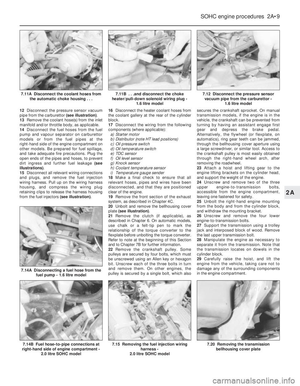
pull-down solenoid (see illustrations). Also
disconnect the air box vacuum pipe from the
carburettor.
2A•8SOHC engine procedures
2.3 Crankcase ventilation filter removed
from camshaft cover -
1.6 litre engine
Page 206 of 525
12Disconnect the pressure sensor vacuum
pipe from the carburettor (see illustration).
13Remove the coolant hose(s) from the inlet
manifold and/or throttle body, as applicable.
14Disconnect the fuel hoses from the fuel
pump and vapour separator on carburettor
models or from the fuel pipes at the
right-hand side of the engine compartment on
other models. Be prepared for fuel spillage,
and take adequate fire precautions. Plug the
open ends of the pipes and hoses, to prevent
dirt ingress and further fuel leakage (see
illustrations).
15Disconnect all relevant wiring connections
and plugs, and remove the fuel injection
wiring harness. Pull up on the wiring harness
housing, and compress the wiring plug
retaining clips to release the harness housing
from the fuel injectors (see illustration).16Disconnect the heater coolant hoses from
the coolant gallery at the rear of the cylinder
block.
17Disconnect the wiring from the following
components (where applicable):
a)Starter motor
b)Distributor (note HT lead positions)
c)Oil pressure switch
d)Oil temperature switch
e)TDC sensor
f)Oil level sensor
g)Knock sensor
h)Coolant temperature sensor
i)Temperature gauge sender
18Make a final check to ensure that all
relevant hoses, pipes and wires have been
disconnected, and that they are positioned
clear of the engine.
19Remove the front section of the exhaust
system, as described in Chapter 4C.
20Unbolt and remove the bellhousing cover
plate (see illustration).
21Remove the clutch (if applicable), as
described in Chapter 6. On automatic models,
use chalk or a felt-tip pen to mark the
relationship of the torque converter to the
flexplate before unbolting the torque converter.
Refer to note at the beginning of this Section
and to Chapter 7B for further information.
22Remove the crankshaft pulley. Some
pulleys are secured by four bolts, which must
be unscrewed using an Allen key or hexagon
bit. Unscrew each of the three bolts in turn
and remove them. On other engines, the
pulley is secured by a single bolt, which alsosecures the crankshaft sprocket. On manual
transmission models, if the engine is in the
vehicle, the crankshaft can be prevented from
turning by having an assistant engage first
gear and depress the brake pedal.
Alternatively, the flywheel (or flexplate, on
automatics), ring gear teeth can be jammed,
through the bellhousing cover aperture using
a large screwdriver, or similar tool. Access to
the crankshaft pulley is most easily obtained
through the right-hand wheel arch, after
removing the roadwheel.
23Attach a hoist and lifting gear to the
engine lifting brackets on the cylinder head,
and support the weight of the engine.
24Unscrew and remove two of the three
upper engine-to-transmission bolts,
accessible from the engine compartment,
leaving one fastened for safety.
25Unbolt the right-hand engine mounting
from the body and from the cylinder block,
and withdraw the mounting bracket.
26Unscrew and remove the four lower
engine-to-transmission bolts.
27Support the transmission using a trolley
jack and interposed block of wood. Remove
the last upper transmission bolt.
28Manipulate the engine as necessary to
separate it from the transmission. Note that
the transmission locates on dowels in the
cylinder block.
29Carefully raise the hoist, and lift the
engine from the vehicle, taking care not to
damage any of the surrounding components
in the engine compartment.
SOHC engine procedures 2A•9
7.12 Disconnect the pressure sensor
vacuum pipe from the carburettor -
1.6 litre model
7.20 Removing the transmission
bellhousing cover plate7.15 Removing the fuel injection wiring
harness -
2.0 litre SOHC model7.14B Fuel hose-to-pipe connections at
right-hand side of engine compartment -
2.0 litre SOHC model
7.14A Disconnecting a fuel hose from the
fuel pump - 1.6 litre model
7.11B . . .and disconnect the choke
heater/pull-down solenoid wiring plug -
1.6 litre model7.11A Disconnect the coolant hoses from
the automatic choke housing . . .
2A