1988 OPEL CALIBRA fuel pump
[x] Cancel search: fuel pumpPage 70 of 525

12•56Wiring diagrams
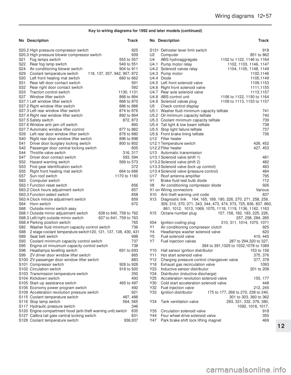
Key to wiring diagrams for 1992 and later models (continued)
NoDescriptionTrackNoDescriptionTrack
K95Traction control control unit1125 to 1140
K97Headlamps washer pump time delay relay630 to 632
K101Parking position mirror relay774 to 777
K102Park brake shift lock control unit 469 to 471
L1Ignition coil150, 172, 205, 273, 241, 302, 361
L2Ignition coil1000 to 1004, 1054 to 1059
M1Starter105, 106
M2Windshield wiper motor601 to 604
M3Heating blower motor127 to 129
M4Radiator blower motor118, 120, 140, 356, 431, 948, 954, 980
M6Left headlamp wiper motor622 to 624
M7Right headlamp wiper motor 626 to 628
M8Back window wiper motor611 to 613
M10Air conditioning blower motor905 to 908
M11Radiator blower motor136, 434, 962, 984
M13Vectra/Cavalier sun roof motor1172 to 1175
M13.1Sun roof motor1172, 1174
M13.2Timing box microswitch1172
M13.3Timing box microswitch1174
M18Driver door central locking motor807 to 810
M19Left rear door central locking motor821 to 823
M20Right rear door central locking motor825 to 827
M21Fuel pump232, 263, 297, 339, 399, 834, 1098, 1039
M23Alternator blower motor135, 974
M24Headlamps washer pump632
M26Automatic antenna motor798 to 799
M30Driver side outside mirror638 to 641
M31Passenger side outside mirror644 to 647
M32Passenger door central locking motor813 to 816
M33Idle speed actuator285, 286, 317, 318, 381,
382, 1019, 1020, 1075, 1076
M37Tail gate/boot lid central locking motor818 to 821
M39Left headlamp levelling motor 692 to 695
M40Right headlamp levelling motor696 to 699
M41Fuel filler door central locking motor823, 824
M47Driver door window lifter motor867 to 871
M48Passenger door window lifter motor885 to 889
M49Left rear window lifter motor873 to 877
M50Right rear window lifter motor891 to 895
M55Windshield and back window washer pump617
M57Coolant pump134, 970
M60Calibra tailgate central locking motor827, 828
M61Calibra sun roof motor1178 to 1186
M61.1Sun roof motor1179 to 1182
M61.2Relay 11178, 1179
M61.3Relay 21184 to 1186
M62Driver side outside mirror760 to 767
M63Passenger side outside mirror769 to 776
M65TC throttle valve actuator1130 to 1134
M66Idle air stepper motor215 to 218, 250 to 253
P1Fuel indicator704
P2Coolant temperature indicator706
P3Clock862
P4Fuel sensor704
P5Coolant temperature sensor706
P7Tachometer708
P11Airflow meter 285 to 289
P12Coolant temperature sensor282, 381
P13Outside temperature sensor856
P14Distance sensor412, 413
P17Left front revolution sensor1110, 1154
P18Right front revolution sensor1113, 1157
P19Left rear revolution sensor1116, 1160
P20Right rear revolution sensor1119, 1163P21Distance sensor731
P23Intake manifold absolute pressure sensor160, 161, 185, 186,
217 to 219, 250 to 252
P24Engine oil temperature sensor162, 187
P27Left front brake lining sensor740
P28Right front brake lining sensor740
P29Intake manifold temperature sensor382, 1016, 1072
P30Coolant temperature sensor215, 248, 313, 1017, 1073
P32Heated exhaust oxygen sensor294, 295, 331, 332, 391,
392, 1034, 1035, 1093, 1094
P33Exhaust oxygen sensor229, 257
P34Throttle valve potentiometer221 to 223, 280, 281, 253 to 255,
383 to 385, 478, 479, 1018, 1019, 1074, 1075
P35Crankshaft impulse sensor178 to 180, 289 to 291, 248 to 250,
318 to 320, 373 to 375, 1025 to 1027, 1084 to 1086
P38Transmission oil temperature sensor494
P39Trailer bulb test sensor752 to 754
P43Electronic speedometer733
P44Air mass meter393 to 397, 334 to 338,
1037, 1038, 1096, 1097
P45Transmission input revolution sensor490, 491
P46Knock control sensor322, 323, 377, 378,
1022, 1023, 1078, 1079
P47Cylinder identification hall sensor325 to 327, 385 to 387,
1028 to 1030, 1087, 1089
P48Automatic transmission distance sensor488, 489
P50Catalytic converter temperature sensor463, 464
P53Driver side anti-theft warning unit sensor839 to 847
P54Passenger side anti-theft warning unit sensor839 to 847
P55Engine coolant temperature sensor415
P56Knock control sensor II1080, 1081
P57Antenna797
R3Cigarette lighter675
R5Glow plugs418 to 420, 441 to 443
R13Left heated washer nozzle 626
R14Right heated washer nozzle628
R19Radiator blower preresistor120, 140, 945
R22Glow plugs pre-resistor423
R23Driver airbag squib1194
S1Starter switch103 to 106
S1.2Key contact switch783
S2Light switch assy
S2.1Light switch504 to 507
S2.2Passenger compartment lamp switch587
S2.3Instrument lights dimmer728
S3Heating blower switch123 to 130
S4Heated back window & mirror switch654 to 657
S5Turn signal switch assy
S5.2Low beam switch536, 537
S5.3Turn signal switch580 to 582
S5.4Parking lamp switch501, 502
S7Back up lamp switch597, 599
S8Stop lamp switch562
S9Wiper unit switch
S9.2Interval windshield wiper switch601 to 604
S9.5Back window and washer unit wiper switch614 to 616
S10Automatic transmission switch472 to 478
S11Brake fluid control switch712
S13Parking brake switch713
S14Oil pressure switch710
S15Boot lamp switch585
S17Passenger door contact switch590
S20Pressure switch
S20.1Low pressure compressor switch925
Page 71 of 525
Wiring diagrams 12•57
12
Key to wiring diagrams for 1992 and later models (continued)
NoDescriptionTrackNoDescriptionTrack
S20.2High pressure compressor switch925
S20.3High pressure blower compressor switch939
S21Fog lamps switch555 to 557
S22Rear fog lamp switch549 to 551
S24Air conditioning blower switch904 to 911
S29Coolant temperature switch118, 137, 357, 942, 957, 972
S30Left front heating mat switch660 to 662
S31Rear left door contact switch591
S32Rear right door contact switch592
S33Traction control switch1130, 1131
S37Window lifter switch868 to 894
S37.1Left window lifter switch868 to 870
S37.2Right window lifter switch886 to 888
S37.3Left rear window lifter switch874 to 876
S37.4Right rear window lifter switch892 to 894
S37.5Safety switch872, 873
S37.6Window anti-jam off switch890
S37.7Automatic window lifter control877 to 882
S39Left rear door window lifter switch878 to 880
S40Right rear door window lifter switch896 to 898
S41Driver door burglary locking switch800 to 802
S42Passenger door central locking switch805
S44Throttle valve switch316, 317
S47Driver door contact switch593, 594
S52Hazard warning switch569 to 573
S53First gear identification switch372
S55Right front heating mat switch664 to 666
S57Sun roof switch1170 to 1183
S63Computer switch
S63.1Function reset switch856
S63.2Clock hours adjustment switch857
S63.3Function select switch858
S63.4Clock minute adjustment switch859
S64Horn switch672
S68Outside mirror switch assy
S68.1Outside mirror adjustment switch638 to 640, 758 to 762
S68.3Left/right outside mirror switch637 to 641, 759 to 763
S68.4Parking position switch765
S82Washer fluid minimum capacity control switch736
S882 stage coolant temperature switch120, 121, 137, 138, 430, 431
S89Seat belt switch998
S93Coolant minimum capacity control switch737
S95Engine oil minuimum capacity control switch738
S98Headlamps levelling switch691 to 693
S99ZV driver door window lifter switch865
S100ZV passenger door window lifter switch883
S101Compressor switch926 to 928
S102Circulation switch918 to 920
S103Transmission temperature switch350
S104Kickdown switch493
S105Start-up assistance switch495 to 497
S106Economy power program switch492
S109Acceleration revolution pressure switch921
S115Coolant temperature switch487, 488
S116Stop lamp switch564, 565
S117Hydraulic pressure switch346
S120Engine compartment hood (anti-theft warning unit) switch835
S127Calibra tail gate central locking switch831
S128Coolant temperature switch936,937S131Defroster lever limit switch918
U2Computer851 to 862
U4ABS hydroaggregate1102 to 1122, 1146 to 1164
U4.1Pump motor relay1102, 1103, 1146, 1147
U4.2Solenoid valves relay1104, 1105, 1148, 1149
U4.3Pump motor1102,1146
U4.4Diode1105,1149
U4.5Left front solenoid valve1109,1153
U4.6Right front solenoid valve1111,1155
U4.7Rear axle solenoid valve1113,1157
U4.8ABS control unit1106 to 1122, 1150 to 1164
U4.9Solenoid valves plug1109 to 1113, 1153 to 1157
U5Check control display
U5.1Washer fluid minimum capacity telltale741
U5.2Oil minimum capacity telltale740
U5.3Coolant minimum capacity telltale739
U5.4Tail light & low beam telltale738
U5.5Stop light failure telltale737
U5.6Front brake lining telltale736
U12Filter heater
U12.1Temperature switch426, 452
U12.2Filter heater427, 453
U13Automatic transmission
U13.1Solenoid valve (shift 1)481
U13.2Solenoid valve (shift 2)482
U13.3Solenoid valve (lock up control)483
U13.4Solenoid valve (pressure control)484
U17Roof antenna amplifier795
V1Brake fluid test bulb diode712
V8Air conditioning compressor diode926
X1 onWiring connectorsVarious
X10Anti theft warning unit code837
X13Diagnostic link164, 165, 189, 190, 226, 270, 271, 258, 259,
309, 310, 370, 371, 343, 344, 473, 474, 573, 725, 836, 837, 860,
861, 1012, 1013, 1069, 1070, 1118, 1119, 1136, 1162, 1163
X15Octane number plug157, 158, 182, 183, 225, 226,
257, 258, 284, 285
X54Ignition coding plug310, 311, 1014, 1070, 1071
Y1Air conditioning compressor clutch925
Y4Headlamps washer solenoid valve620
Y5Fuel solenoid valve410, 445
Y7Fuel injection valves287 to 294,320 to 327,
384 to 391,1025 to 1032,1078 to 1089
Y10Hall sensor ignition distributor153 to 158
Y11Hot start solenoid valve375, 376
Y12Charging pressure control changeover valve377, 378
Y18Exhaust gas recirculation valve1093
Y23Inductive sensor distributor201 to 208
Y24Distributor (inductive discharge)
Y25Acceleration revolution solenoid valve155, 177
Y30Cold start acceleration solenoid valve 448
Y32Fuel injection valve212, 245
Y33Ignition distributor175 to 177, 268 to 270, 238 to 240,
301 to 303, 360 to 362
Y34Tank ventilation valve293, 331, 332, 379, 380,
1092, 1016, 1017,
Y35Circulation solenoid valve918
Y44Four wheel drive solenoid valve350
Y47Park brake shift lock lifting magnet469
Page 90 of 525

HEI (High Energy Ignition)
system
5This comprises of a breakerless distributor
and an electronic switching/amplifier module
along with the coil and spark plugs.
6The electrical impulse that is required to
switch off the low tension circuit is generated
by a magnetic trigger coil in the distributor. A
trigger wheel rotates within a magnetic stator,
the magnetic field being provided by a
permanent magnet. The magnetic field across
the two poles (stator arm and trigger wheel) is
dependent on the air gap between the two
poles. When the air gap is at its minimum, the
trigger wheel arm is directly opposite the
stator arm, and this is the trigger point. As the
magnetic flux between the stator arm and
trigger wheel varies, a voltage is induced in the
trigger coil mounted below the trigger wheel.
This voltage is sensed and then amplified by
the electronic module, and used to switch off
the low tension circuit. There is one trigger arm
and one stator arm for each cylinder.
7The ignition advance is a function of the
distributor, and is controlled both
mechanically and by a vacuum-operated
system. The mechanical governor mechanism
consists of two weights that move out from
the distributor shaft due to centrifugal force as
the engine speed rises. As the weights move
outwards, they rotate the trigger wheel
relative to the distributor shaft and so
advance the spark. The weights are held in
position by two light springs, and it is the
tension of the springs that is largely
responsible for correct spark advancement.
8The vacuum control consists of a
diaphragm, one side of which is connected by
way of a small-bore hose to the carburettor,
and the other side to the distributor.
Depression in the inlet manifold and
carburettor, which varies with engine speed
and throttle position, causes the diaphragm to
move, so moving the baseplate and
advancing or retarding the spark. A fine
degree of control is achieved by a spring in
the diaphragm assembly.
MSTS-i (Microprocessor-
controlled Spark Timing System)
9This system comprises a “Hall-effect”
distributor (or a crankshaft speed/position
sensor on X 16 SZ models), a manifold pressure
sensor, an oil temperature sensor, and a
module, along with the coil and spark plugs.
10On 1.6 litre models, the electrical impulse
that is required to switch off the low tension
circuit is generated by a sensor in the
distributor. A trigger vane rotates in the gap
between a permanent magnet and the sensor.
The trigger vane has four cut-outs, one for
each cylinder. When one of the trigger vane
cut-outs is in line with the sensor, magnetic
flux can pass between the magnet and the
sensor. When a trigger vane segment is in line
with the sensor, the magnetic flux is diverted
through the trigger vane away from thesensor. The sensor senses the change in
magnetic flux, and sends an impulse to the
MSTS-i module, which switches off the low
tension circuit.
11On 1.8 litre models, the electrical impulse
that is required to switch off the low tension
circuit is generated by a crankshaft
speed/position sensor, which is activated by a
toothed wheel on the crankshaft. The toothed
wheel has 35 equally spaced teeth, with a gap
in the 36th position. The gap is used by the
sensor to determine the crankshaft position
relative to TDC (top dead centre) of No 1 piston.
12Engine load information is supplied to the
MSTS-i module by a pressure sensor, which
is connected to the carburettor by a vacuum
pipe. Additional information is supplied by an
oil temperature sensor. The module selects
the optimum ignition advance setting based
on the information received from the sensors.
The degree of advance can thus be constantly
varied to suit the prevailing engine conditions.
Multec, with MSTS-i
13The ignition system is fully electronic in
operation and incorporates the Electronic
Control Unit (ECU) mounted in the driver’s
footwell. A distributor (driven off the camshaft
left-hand end and incorporating the amplifier
module) as well as the octane coding plug,
the spark plugs, HT leads, ignition HT coil and
associated wiring.
14The ECU controls both the ignition system
and the fuel injection system, integrating the
two in a complete engine management
system. Refer to Chapters 4B and 4C for
further information that is not detailed here.
15For ignition the ECU receives information
in the form of electrical impulses or signals
from the distributor (giving it the engine speed
and crankshaft position), from the coolant
temperature sensor (giving it the engine
temperature) and from the manifold absolute
pressure sensor (giving it the load on the
engine). In addition, the ECU receives input
from the octane coding plug (to provide
ignition timing appropriate to the grade of fuel
used) and from, where fitted, the automatic
transmission control unit (to smooth gear
changing by retarding the ignition as changes
are made).
16All these signals are compared by the
ECU with set values pre-programmed
(mapped) into its memory. Considering this
information, the ECU selects the ignition
timing appropriate to those values and
controls the ignition HT coil by way of the
amplifier module accordingly.
17The system is so sensitive that, at idle
speed, the ignition timing may be constantly
changing; this should be remembered if trying
to check the ignition timing.
18The system fitted to C18 NZ models, is
similar to that described above, except that
the amplifier module is separate. The ECU
determines engine speed and crankshaft
position using a sensor mounted in the
right-hand front end of the engine’s cylinderblock; this registers with a 58-toothed disc
mounted on the crankshaft so that the gap left
by the missing two teeth provides a reference
point, so enabling the ECU to recognise TDC.
19Note that this simplifies the distributor’s
function, which is merely to distribute the HT
pulse to the appropriate spark plug; it has no
effect whatsoever on the ignition timing.
DIS (Direct Ignition System)
20On all X16 SZ engines, and on C20 XE
(DOHC) engines from 1993-on, a DIS (Direct
Ignition System) module is used in place of
the distributor and coil. On the X16 SZ engine
the DIS module is attached to the camshaft
housing in the position normally occupied by
the distributor. On the C20 XE engine, a
camshaft phase sensor is attached to the
cylinder head at the non-driven end of the
exhaust camshaft, in the position normally
occupied by the distributor. The DIS module
is attached, by a bracket, to the cylinder head
at the non-driven end of the inlet camshaft.
21The DIS module consists of two ignition
coils and an electronic control module housed
in a cast casing. Each ignition coil supplies
two spark plugs with HT voltage. One spark is
provided in a cylinder with its piston on the
compression stroke, and one spark is
provided to a cylinder with its piston on the
exhaust stroke. This means that a “wasted
spark” is supplied to one cylinder during each
ignition cycle, but this has no detrimental
effect. This system has the advantage that
there are no moving parts (therefore there is
no wear), and the system is largely
maintenance-free.
Motronic M4.1 and M1.5
22This system controls both the ignition and
the fuel injection systems.
23The Motronic module receives information
from a crankshaft speed/position sensor, an
engine coolant temperature sensor mounted
in the thermostat housing. A throttle position
sensor, an airflow meter, and on models fitted
with a catalytic converter, an oxygen sensor
mounted in the exhaust system (Chapter 4C).
24The module provides outputs to control
the fuel pump, fuel injectors, idle speed and
ignition circuit. Using the inputs from the
various sensors, the module computes the
optimum ignition advance, and fuel injector
pulse duration, to suit the prevailing engine
conditions. This system gives very accurate
control of the engine under all conditions,
improving fuel consumption and driveability,
and reducing exhaust gas emissions.
25Further details of the fuel injection system
components are given in Chapter 4B.
Motronic M2.5 and M2.8
26The system is similar to that described for
SOHC models, with the following differences.
27Along with the crankshaft speed/position
sensor, a “Hall-effect” distributor is used
(similar to that described in this Section, with
the MSTS-i system).
Engine electrical systems 5•3
5
Page 102 of 525
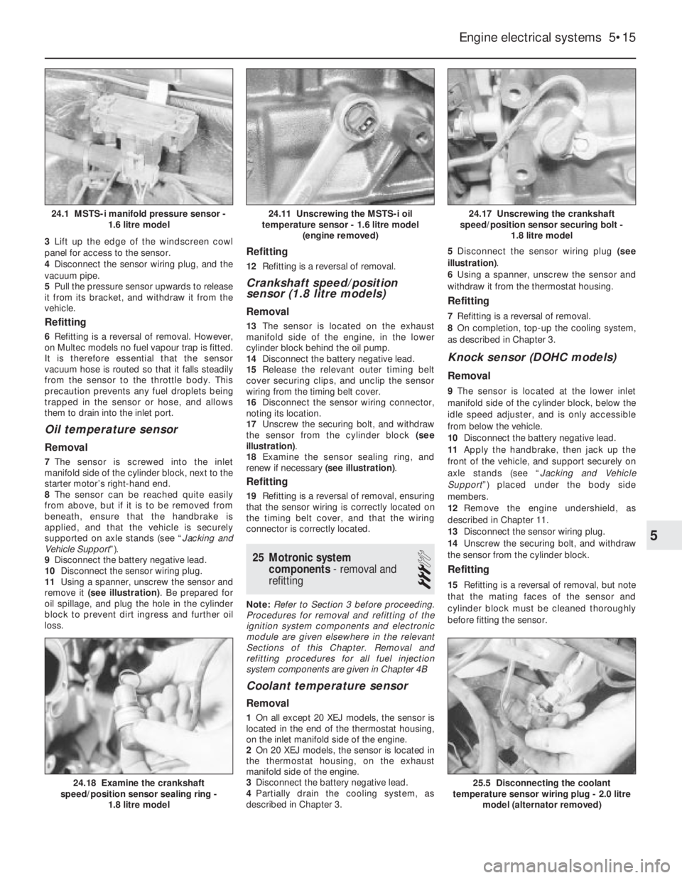
3Lift up the edge of the windscreen cowl
panel for access to the sensor.
4Disconnect the sensor wiring plug, and the
vacuum pipe.
5Pull the pressure sensor upwards to release
it from its bracket, and withdraw it from the
vehicle.
Refitting
6Refitting is a reversal of removal. However,
on Multec models no fuel vapour trap is fitted.
It is therefore essential that the sensor
vacuum hose is routed so that it falls steadily
from the sensor to the throttle body. This
precaution prevents any fuel droplets being
trapped in the sensor or hose, and allows
them to drain into the inlet port.
Oil temperature sensor
Removal
7The sensor is screwed into the inlet
manifold side of the cylinder block, next to the
starter motor’s right-hand end.
8The sensor can be reached quite easily
from above, but if it is to be removed from
beneath, ensure that the handbrake is
applied, and that the vehicle is securely
supported on axle stands (see “Jacking and
Vehicle Support”).
9Disconnect the battery negative lead.
10Disconnect the sensor wiring plug.
11Using a spanner, unscrew the sensor and
remove it (see illustration). Be prepared for
oil spillage, and plug the hole in the cylinder
block to prevent dirt ingress and further oil
loss.
Refitting
12Refitting is a reversal of removal.
Crankshaft speed/position
sensor (1.8 litre models)
Removal
13The sensor is located on the exhaust
manifold side of the engine, in the lower
cylinder block behind the oil pump.
14Disconnect the battery negative lead.
15Release the relevant outer timing belt
cover securing clips, and unclip the sensor
wiring from the timing belt cover.
16Disconnect the sensor wiring connector,
noting its location.
17Unscrew the securing bolt, and withdraw
the sensor from the cylinder block (see
illustration).
18Examine the sensor sealing ring, and
renew if necessary (see illustration).
Refitting
19Refitting is a reversal of removal, ensuring
that the sensor wiring is correctly located on
the timing belt cover, and that the wiring
connector is correctly located.
25Motronic system
components - removal and
refitting
3
Note: Refer to Section 3 before proceeding.
Procedures for removal and refitting of the
ignition system components and electronic
module are given elsewhere in the relevant
Sections of this Chapter. Removal and
refitting procedures for all fuel injection
system components are given in Chapter 4B
Coolant temperature sensor
Removal
1On all except 20 XEJ models, the sensor is
located in the end of the thermostat housing,
on the inlet manifold side of the engine.
2On 20 XEJ models, the sensor is located in
the thermostat housing, on the exhaust
manifold side of the engine.
3Disconnect the battery negative lead.
4Partially drain the cooling system, as
described in Chapter 3. 5Disconnect the sensor wiring plug (see
illustration).
6Using a spanner, unscrew the sensor and
withdraw it from the thermostat housing.
Refitting
7Refitting is a reversal of removal.
8On completion, top-up the cooling system,
as described in Chapter 3.
Knock sensor (DOHC models)
Removal
9The sensor is located at the lower inlet
manifold side of the cylinder block, below the
idle speed adjuster, and is only accessible
from below the vehicle.
10Disconnect the battery negative lead.
11Apply the handbrake, then jack up the
front of the vehicle, and support securely on
axle stands (see “Jacking and Vehicle
Support”) placed under the body side
members.
12Remove the engine undershield, as
described in Chapter 11.
13Disconnect the sensor wiring plug.
14Unscrew the securing bolt, and withdraw
the sensor from the cylinder block.
Refitting
15Refitting is a reversal of removal, but note
that the mating faces of the sensor and
cylinder block must be cleaned thoroughly
before fitting the sensor.
Engine electrical systems 5•15
24.17 Unscrewing the crankshaft
speed/position sensor securing bolt -
1.8 litre model
25.5 Disconnecting the coolant
temperature sensor wiring plug - 2.0 litre
model (alternator removed)24.18 Examine the crankshaft
speed/position sensor sealing ring -
1.8 litre model
24.11 Unscrewing the MSTS-i oil
temperature sensor - 1.6 litre model
(engine removed)24.1 MSTS-i manifold pressure sensor -
1.6 litre model
5
Page 126 of 525
4C
Torque wrench settingsNm lbf ft
AIR non-return valve to pipe . . . . . . . . . . . . . . . . . . . . . . . . . . . . . . . . . . 30 22
AIR pipe support bracket to manifold . . . . . . . . . . . . . . . . . . . . . . . . . . 8 6
AIR pipe to manifold . . . . . . . . . . . . . . . . . . . . . . . . . . . . . . . . . . . . . . . . 20 15
AIR pipe to support bracket . . . . . . . . . . . . . . . . . . . . . . . . . . . . . . . . . . 8 6
AIR pump bracket to protective shield . . . . . . . . . . . . . . . . . . . . . . . . . . 10 7
AIR pump to wheel arch . . . . . . . . . . . . . . . . . . . . . . . . . . . . . . . . . . . . . 20 15
AIR pump to insulator . . . . . . . . . . . . . . . . . . . . . . . . . . . . . . . . . . . . . . . 10 7
AIR valves to bracket . . . . . . . . . . . . . . . . . . . . . . . . . . . . . . . . . . . . . . . 4 3
Carbon canister . . . . . . . . . . . . . . . . . . . . . . . . . . . . . . . . . . . . . . . . . . . 4 3
EGR valve . . . . . . . . . . . . . . . . . . . . . . . . . . . . . . . . . . . . . . . . . . . . . . . . 20 15
Heat shield . . . . . . . . . . . . . . . . . . . . . . . . . . . . . . . . . . . . . . . . . . . . . . . 8 6
Oxygen sensor . . . . . . . . . . . . . . . . . . . . . . . . . . . . . . . . . . . . . . . . . . . . 30 22
Chapter 4 Part C:
Fuel and exhaust systems - exhaust and emissions
AIR cut-off valve - removal, testing and refitting . . . . . . . . . . . . . . . . .7
AIR pipe and non-return valve - removal and refitting . . . . . . . . . . . . .9
AIR pump assembly (Simtec system) - removal and refitting . . . . . . . .6
AIR switchover valve - removal and refitting . . . . . . . . . . . . . . . . . . . .8
Carbon canister - removal and refitting . . . . . . . . . . . . . . . . . . . . . . .11
Catalytic converter - description, general and precautions . . . . . . . .10
EGR module (X 16 SZ models) - removal and refitting . . . . . . . . . . . . .5EGR valve (Multec system models) - testing, removal and refitting . . .3
EGR valve (Simtec system) - testing, removal and refitting . . . . . . . . .4
Emissions control systems - general . . . . . . . . . . . . . . . . . . . . . . . . . .1
Exhaust gas recirculation (EGR) system - general . . . . . . . . . . . . . . . .2
Exhaust manifold - removal and refitting . . . . . . . . . . . . . . . . . . . . . .13
Exhaust system - checking, removal and refitting . . . . . . . . . . . . . . .14
Oxygen sensor (catalytic converter models) - removal and refitting .12
4C•1
Specifications Contents
1 Emissions control systems -
general
General
Multec system
1An evaporative emissions control system is
fitted to minimise the escape into the
atmosphere of unburned hydrocarbons.
2The fuel tank filler cap is sealed and a
charcoal canister is mounted under the
right-hand front wing to collect the petrol
vapours generated in the tank when the
vehicle is parked. It stores them until they can
be purged from the canister into the inlet tract
to be burned by the engine during normal
combustion. The canister’s control valve (on
the top of the canister) is opened by a vacuum
pipe from the front of the throttle body on C16
NZ, C16 NZ2 and C18 NZ engines. On X16 SZ
it’s opened by an electronically activated
purge valve, mounted on the camshaft
housing.
Motronic system
3The system is as described in Chapter 4B,
except that the charcoal canister is purged
under the control of the fuel injection/ignition
system module through the fuel tank vent
valve. To ensure that the engine runs correctly
when it is cold and/or idling, and to protect
the catalytic converter from the effects of an
over-rich mixture, the valve is not opened by
the module until the engine is under partial or
full load. The valve solenoid is then modulated
on and off to allow the stored vapour to pass
into the inlet tract.
4Canister removal and refitting is as
described in Section 11.
5On C20 NE engines, the vent valve is
mounted above the injectors for cylinders 2
and 4. To remove it, disconnect the battery
negative lead and the valve wiring plug, then
disconnect the two vent hoses having made
note of their connections. Either remove the
valve from its mounting bracket, or unbolt the
bracket, as required.
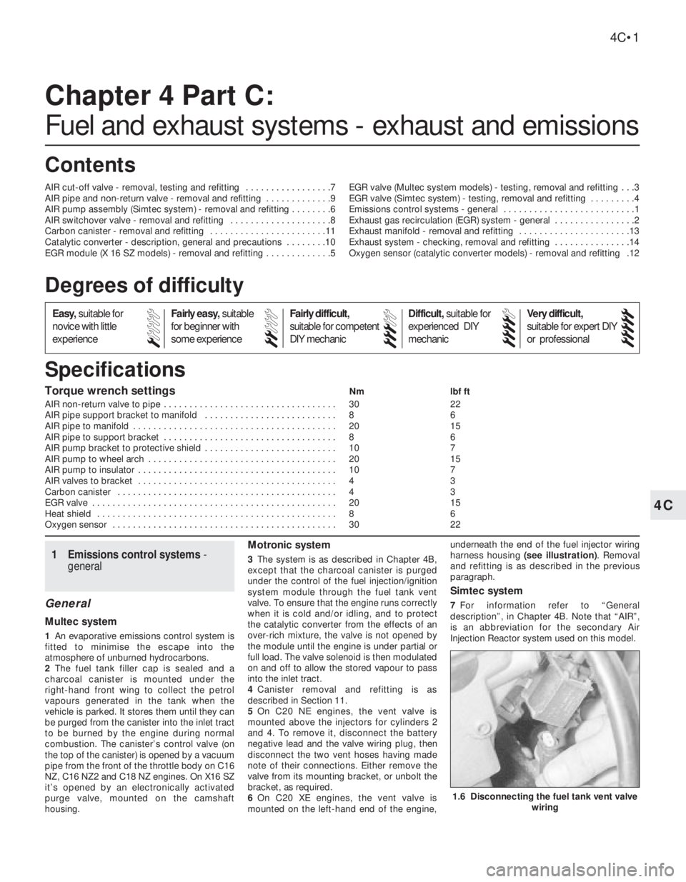
6On C20 XE engines, the vent valve is
mounted on the left-hand end of the engine,underneath the end of the fuel injector wiring
harness housing (see illustration). Removal
and refitting is as described in the previous
paragraph.
Simtec system
7For information refer to “General
description”, in Chapter 4B. Note that “AIR”,
is an abbreviation for the secondary Air
Injection Reactor system used on this model.
Easy,suitable for
novice with little
experienceFairly easy,suitable
for beginner with
some experienceFairly difficult,
suitable for competent
DIY mechanic
Difficult,suitable for
experienced DIY
mechanicVery difficult,
suitable for expert DIY
or professional
Degrees of difficulty
54321
1.6 Disconnecting the fuel tank vent valve
wiring
Page 127 of 525

2Exhaust gas recirculation
(EGR) system - general
The system reintroduces small amounts of
exhaust gas into the combustion cycle to
reduce the generation of oxides of nitrogen
(NOx).
On C16 NZ, C16 NZ2 and C18 NZ engines,
the volume of exhaust gas reintroduced is
governed by manifold vacuum, through the
EGR valve mounted on the inlet manifold.
When the valve is opened small amounts of
exhaust gas are allowed to enter the inlet
tract, passing through ports in the cylinder
head.
On X16 SZ engines the EGR valve is
operated by an EGR module, mounted on the
left-hand side of the engine compartment
behind the battery. This module amplifies
signals received from the fuel system ECU
and operates the EGR valve electronically
providing precise control of exhaust gas
recirculation under all engine conditions.
3EGR valve (Multec system
models) - testing, removal and
refitting
2
Testing
1On C16 NZ, C16 NZ2 and C18 NZ engines,
it is recommended that the system is checked
annually, by checking the movement of the
valve’s diaphragm carrier plate as follows.
Note that the carrier plate is visible only
through the apertures in the underside of the
valve, so a battery-operated torch and small
mirror may be useful. On X16 SZ engines,
Vauxhall test equipment is necessary to check
the EGR system.
2With the engine fully warmed up to normal
operating temperature and idling, briefly open
and close the throttle. The carrier plate should
move upwards as the manifold vacuum
changes. When the engine is idling smoothly
again, press the carrier plate upwards (do this
very carefully, so that the plate is not distorted or
the diaphragm damaged). The idle speed should
drop significantly (approximately 100 rpm).
3If the valve does not respond as described,
it must be cleaned.
Removal
4Pull off the hose from the valve, then unbolt
the valve and remove it (see illustrations).
Clean away all carbon using a wire brush and
a pointed tool, but take care not to damage
the valve seat. Renew the valve gasket to
prevent induction leaks.
Refitting
5Refit the valve and reconnect the hose,
then recheck the system’s performance; if
there is no improvement, the valve must be
renewed.
4EGR valve (Simtec system) -
testing, removal and refitting
3
Note: A new gasket will be required when
refitting the valve.
Removal
1Disconnect the battery negative lead.
2Remove wiring harness and vacuum hose.
3Mark position of the valve, to ensure
correct relocation.
4Undo the 3 bolts, and remove the valve
from the dual spark ignition coil’s coolant
flange.
Refitting
5Clean the sealing surfaces of the valve and
flange.
6Refit the valve with a new gasket and line
up the marks made before removal (see
illustration).
5EGR module (X16 SZ
models) - removal and
refitting
2
Removal
1Disconnect the knock module from its
bracket (refer to Chapter 4B, if necessary),
and place to one side.
2Remove wiring plug from module. Remove
module from bracket.
Refitting
3Refitting is a reversal of removal.
6AIR pump assembly (Simtec
system) - removal and refitting
3
Removal
1Chock the rear wheels, jack up the front of
the vehicle and support it on axle stands
placed under the body side members (see
“Jacking and Vehicle Support”)
2Remove the left hand front wheel and inner
wheel arch lining.
3Loosen the hose clamp and remove the air
duct hose from the pump.
4Disconnect the battery negative lead.
5Undo the securing nuts and remove the
pump assembly from its location. Disconnect
the wiring plug.
6Remove the wiring plug from the pump’s
bracket.
7Mark the position of the pump on it’s
bracket before separating.
8Remove the fixing bolts and disconnect the
pump from it’s insulator.
9The insulator can also be checked by
removing the 3 nuts, securing the protective
shield. Before removing, mark the shield and
insulator. Replace if necessary.
10Check the pump’s air cleaner for damage.
Refitting
11Refitting is a reversal of removal. Ensure
correct alignment of the components.
7AIR cut-off valve - removal,
testing and refitting
3
Removal
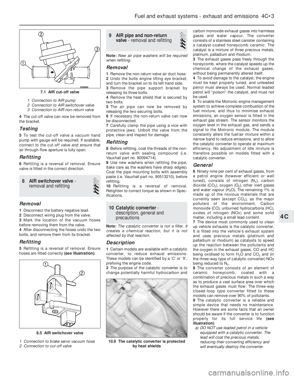
1Before removal, mark on the cut-off valve,
the direction of flow towards the non-return
valve (see illustration).
2Disconnect and remove the air duct and
vacuum hoses.
3Undo the switchover valve’s bolts and
move to one side.
4C•2Fuel and exhaust systems - exhaust and emissions
3.4 Disconnecting the vacuum hose from
the exhaust gas recirculation valve
4.6 EGR valve
1 Valve 2 Gasket
3.4B Withdrawing the exhaust gas
recirculation valve
Page 128 of 525
4The cut-off valve can now be removed from
the bracket.
Testing
5To test the cut-off valve a vacuum hand
pump with gauge will be required. If available,
connect to the cut-off valve and ensure that
air through-flow aperture is fully open.
Refitting
6Refitting is a reversal of removal. Ensure
valve is fitted in the correct direction.
8AIR switchover valve -
removal and refitting
3
Removal
1Disconnect the battery negative lead.
2Disconnect wiring plug from the valve.
3Mark the location of the vacuum hoses
before removing them from the valve.
4After disconnecting the hoses undo the two
bolts, and remove them from its bracket.
Refitting
5Refitting is a reversal of removal. Ensure
hoses are fitted correctly (see illustration).
9AIR pipe and non-return
valve - removal and refitting
3
Note:New air pipe washers will be required
when refitting.
Removal
1Remove the non-return valve air duct hose.
2Undo the bolts engine lifting eye bracket,
and turn the bracket on to its left hand side.
3Remove the pipe support bracket by
releasing its three bolts.
4Remove the heat shield that is secured by
two bolts.
5The air pipe can now be removed by
releasing the two securing bolts.
6If necessary the non-return valve can now
be disconnected.
7Carefully clamp the pipe using a vice with
protective jaws. Unbolt the valve from the
pipe, clean and inspect for damage.
Refitting
8Before refitting, coat the threads of the non-
return valve with sealing compound (i.e.
Vauxhall part no. 90094714).
9Use new washers when refitting the pipe,
(take care as the washers have sharp edges).
Coat the pipe mounting bolts with assembly
paste (i.e. Vauxhall part no. 90513210), before
refitting.
10Refitting is a reversal of removal.
Retighten to correct torque as shown in Spec-
ifications.
10Catalytic converter -
description, general and
precautions
Note: The catalytic converter is not a filter. It
creates a chemical reaction, but it is not
affected by that reaction.
Description
1Certain models are available with a catalytic
converter, to reduce exhaust emissions.
These models can be identified by a ‘C’ or ‘X’,
prefixing the engine code.
2The purpose of the catalytic converter is to
change potentially harmful hydrocarbon andcarbon monoxide exhaust gases into harmless
gases and water vapour. The converter
consists of a stainless steel canister containing
a catalyst-coated honeycomb ceramic. The
catalyst is a mixture of three precious metals,
platinum, palladium and rhodium.
3The exhaust gases pass freely through the
honeycomb, where the catalyst speeds up the
chemical change of the exhaust gases,
without being permanently altered itself.
4To avoid damage to the catalyst, the engine
must be kept properly tuned, and unleaded
petrol must always be used. Normal leaded
petrol will “poison” the catalyst, and must not
be used.
5To enable the Motronic engine management
system to achieve complete combustion of the
fuel mixture, and thus to minimise exhaust
emissions, an oxygen sensor is fitted in the
exhaust gas stream. The sensor monitors the
oxygen level in the exhaust gas, and sends a
signal to the Motronic module. The module
constantly alters the fuel/air mixture within a
narrow band to reduce emissions, and to allow
the catalytic converter to operate at maximum
efficiency. No adjustment of idle mixture is
therefore possible on models fitted with a
catalytic converter.
General
6Ninety-nine per cent of exhaust gases, from
a petrol engine (however efficient or well
tuned), consists of nitrogen (N
2), carbon
dioxide (CO
2), oxygen (O2), other inert gases
and water vapour (H
2O). The remaining 1% is
made up of the noxious materials that are
currently seen (except CO
2), as the major
polluters of the environment. Carbon
monoxide (CO), unburned hydrocarbons (HC),
oxides of nitrogen (NOx) and some solid
matter, including a small lead content.
7The device most commonly used to clean
up vehicle exhausts is the catalytic converter.
It is fitted into the vehicle’s exhaust system
and uses precious metals (platinum and
palladium or rhodium) as catalysts to speed
up the reaction between the pollutants and
the oxygen in the exhaust gases. CO and HC
being oxidised to form H
2O and CO2and (in
the three-way type of catalytic converter) NOx
being reduced to N
2.
8The converter consists of an element of
ceramic honeycomb, coated with a
combination of precious metals in such a way
as to produce a vast surface area over which
the exhaust gases must flow. The three-way
closed-loop type converter fitted to these
models can remove over 90% of pollutants.
9The catalytic converter is a reliable and
simple device that needs no maintenance.
However there are some facts that an owner
should be aware if the converter is to function
properly for its full service life (see
illustration).
a)DO NOT use leaded petrol in a vehicle
equipped with a catalytic converter. The
lead will coat the precious metals,
reducing their converting efficiency and
will eventually destroy the converter.
Fuel and exhaust systems - exhaust and emissions 4C•3
10.9 The catalytic converter is protected
by heat shields
8.5 AIR switchover valve
1 Connection to brake servo vacuum hose
2 Connection to cut-off valve
7.1 AIR cut-off valve
1 Connection to AIR pump
2 Connection to AIR switchover valve
3 Connection to AIR non-return valve
4C
Page 154 of 525
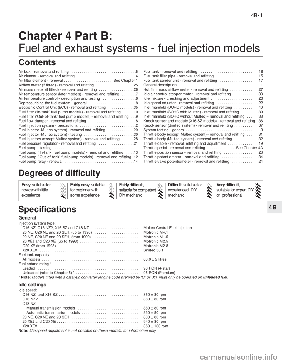
4B
General
Injection system type:
C16 NZ, C16 NZ2, X16 SZ and C18 NZ . . . . . . . . . . . . . . . . . . . . . . . Multec Central Fuel Injection
20 NE, C20 NE and 20 SEH, (up to 1990) . . . . . . . . . . . . . . . . . . . . . Motronic M4.1
20 NE, C20 NE and 20 SEH, (from 1990) . . . . . . . . . . . . . . . . . . . . . . Motronic M1.5
20 XEJ and C20 XE, (up to 1993) . . . . . . . . . . . . . . . . . . . . . . . . . . . . Motronic M2.5
C20 XE (from 1993) . . . . . . . . . . . . . . . . . . . . . . . . . . . . . . . . . . . . . . . Motronic M2.8
X20 XEV . . . . . . . . . . . . . . . . . . . . . . . . . . . . . . . . . . . . . . . . . . . . . . . Simtec 56.1
Fuel tank capacity:
All models . . . . . . . . . . . . . . . . . . . . . . . . . . . . . . . . . . . . . . . . . . . . . . 63.0 ± 2 litres
Fuel octane rating *
Leaded . . . . . . . . . . . . . . . . . . . . . . . . . . . . . . . . . . . . . . . . . . . . . . . . 98 RON (4-star)
Unleaded (refer to Chapter 5) * . . . . . . . . . . . . . . . . . . . . . . . . . . . . . . 95 RON (Premium)
* Note
: Models fitted with a catalytic converter (engine code prefixed by ‘C’ or ‘X’), must only be operated on unleadedfuel.
Idle settings
Idle speed:
C16 NZ and X16 SZ . . . . . . . . . . . . . . . . . . . . . . . . . . . . . . . . . . . . . . 850 ± 80 rpm
C16 NZ2 . . . . . . . . . . . . . . . . . . . . . . . . . . . . . . . . . . . . . . . . . . . . . . . 880 ± 80 rpm
C18 NZ
Manual transmission models . . . . . . . . . . . . . . . . . . . . . . . . . . . . . 880 ± 80 rpm
Automatic transmission models . . . . . . . . . . . . . . . . . . . . . . . . . . . 830 ± 80 rpm
20 NE, C20 NE and 20 SEH . . . . . . . . . . . . . . . . . . . . . . . . . . . . . . . . 800 ± 80 rpm
20 XEJ and C20 XE . . . . . . . . . . . . . . . . . . . . . . . . . . . . . . . . . . . . . . . 940 ± 80 rpm
X20 XEV . . . . . . . . . . . . . . . . . . . . . . . . . . . . . . . . . . . . . . . . . . . . . . . 850 ± 160 rpm
Note:Idle speed adjustment is not possible on these models, for information only
Chapter 4 Part B:
Fuel and exhaust systems - fuel injection models
Air box - removal and refitting . . . . . . . . . . . . . . . . . . . . . . . . . . . . . . .5
Air cleaner - removal and refitting . . . . . . . . . . . . . . . . . . . . . . . . . . . .4
Air filter element - renewal . . . . . . . . . . . . . . . . . . . . . . . .See Chapter 1
Airflow meter (if fitted) - removal and refitting . . . . . . . . . . . . . . . . . .25
Air mass meter (if fitted) - removal and refitting . . . . . . . . . . . . . . . . .26
Air temperature sensor (later models) - removal and refitting . . . . . . .7
Air temperature control - description and testing . . . . . . . . . . . . . . . .6
Depressurising the fuel system - general . . . . . . . . . . . . . . . . . . . . . . .8
Electronic Control Unit (ECU) - removal and refitting . . . . . . . . . . . . .35
Fuel filter (‘In-tank’ fuel pump models) - removal and refitting . . . . . .10
Fuel filter (‘Out-of-tank’ fuel pump models) - removal and refitting . . .9
Fuel flow damper - removal and refitting . . . . . . . . . . . . . . . . . . . . . .18
Fuel injection system - precautions . . . . . . . . . . . . . . . . . . . . . . . . . . .2
Fuel injector (Multec system) - removal and refitting . . . . . . . . . . . . .29
Fuel injector (Multec system) - testing . . . . . . . . . . . . . . . . . . . . . . . .30
Fuel injectors (except Multec system) - removal and refitting . . . . . .28
Fuel pressure regulator - removal and refitting . . . . . . . . . . . . . . . . .21
Fuel pump - testing . . . . . . . . . . . . . . . . . . . . . . . . . . . . . . . . . . . . . .11
Fuel pump (‘In-tank’ fuel pump models) - removal and refitting . . . .13
Fuel pump (‘Out-of-tank’ fuel pump models) - removal and refitting .12
Fuel pump relay - renewal . . . . . . . . . . . . . . . . . . . . . . . . . . . . . . . . .14Fuel tank - removal and refitting . . . . . . . . . . . . . . . . . . . . . . . . . . . . .16
Fuel tank filler pipe - removal and refitting . . . . . . . . . . . . . . . . . . . . .15
Fuel tank sender unit - removal and refitting . . . . . . . . . . . . . . . . . . .17
General description . . . . . . . . . . . . . . . . . . . . . . . . . . . . . . . . . . . . . . .1
Hot film mass airflow meter - removal and refitting . . . . . . . . . . . . . .27
Idle air control stepper motor - removal and refitting . . . . . . . . . . . . .33
Idle mixture - checking and adjustment . . . . . . . . . . . . . . . . . . . . . . .20
Idle speed adjuster - removal and refitting . . . . . . . . . . . . . . . . . . . . .22
Inlet manifold (DOHC models) - removal and refitting . . . . . . . . . . . .40
Inlet manifold (SOHC with Multec) - removal and refitting . . . . . . . . .39
Inlet manifold (SOHC without Multec) - removal and refitting . . . . . .38
Knock sensor and module (X16 SZ models) - removal and refitting .36
Knock sensor (Simtec system) - removal and refitting . . . . . . . . . . . .37
System testing - general . . . . . . . . . . . . . . . . . . . . . . . . . . . . . . . . . . . .3
Throttle body (except Multec system) - removal and refitting . . . . . .31
Throttle body (Multec system) - removal and refitting . . . . . . . . . . . .32
Throttle cable - removal, refitting and adjustment . . . . . . . . . . . . . . .19
Throttle pedal - removal and refitting . . . . . . . . . . . . . .See Chapter 4A
Throttle position sensor - removal and refitting . . . . . . . . . . . . . . . . .23
Throttle potentiometer - removal and refitting . . . . . . . . . . . . . . . . . .34
Throttle valve potentiometer - removal and refitting . . . . . . . . . . . . .24
4B•1
Specifications Contents
Easy,suitable for
novice with little
experienceFairly easy,suitable
for beginner with
some experienceFairly difficult,
suitable for competent
DIY mechanic
Difficult,suitable for
experienced DIY
mechanicVery difficult,
suitable for expert DIY
or professional
Degrees of difficulty
54321