1988 OPEL CALIBRA wheel bolts
[x] Cancel search: wheel boltsPage 183 of 525
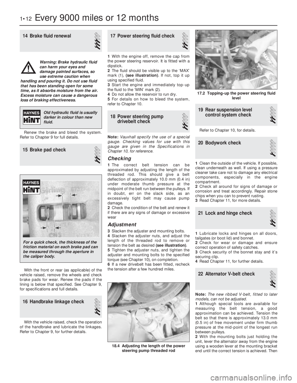
14Brake fluid renewal
3
Renew the brake and bleed the system.
Refer to Chapter 9 for full details.
15Brake pad check
2
With the front or rear (as applicable) of the
vehicle raised, remove the wheels and check
brake pads for wear. Renew the pads if the
lining is below that specified. See Chapter 9,
for specifications and full details.
16Handbrake linkage check
2
With the vehicle raised, check the operation
of the handbrake and lubricate the linkages.
Refer to Chapter 9, for further details.
17Power steering fluid check
2
1With the engine off, remove the cap from
the power steering reservoir. It is fitted with a
dipstick.
2The fluid should be visible up to the ‘MAX’
mark (1), (see illustration). If not, top it up
using specified fluid.
3Start the engine and immediately top-up
the fluid to the ‘MIN’ mark (2).
4Do not allow the reservoir to run dry.
5For details on how to bleed the system,
refer to Chapter 10.
18Power steering pump
drivebelt check
2
Note:Vauxhall specify the use of a special
gauge. Checking values for use with this
gauge are given in the Specifications in
Chapter 10, for reference.
Checking
1The correct belt tension can be
approximated by adjusting the length of the
threaded rod. This should give a belt
deflection of approximately 10.0 mm (0.4 in)
under moderate thumb pressure at the
midpoint of the belt run between the pulleys. If
in doubt, err on the slack side, as an
excessively tight belt may cause pump
damage.
2Check the condition of the belt and renew it
if there are any signs of damage or excessive
wear
Adjustment
3Slacken the adjuster and mounting bolts.
4Slacken the adjuster nuts, and adjust the
length of the threaded rod to remove or
tension the belt as desired (see illustration).
5Tighten the adjuster nuts, and tighten the
adjuster and mounting bolts to the specified
torque (see Chapter 10), on completion.
6If a new drivebelt has been fitted, recheck
the tension after a few hundred miles.
19Rear suspension level
control system check
2
Refer to Chapter 10, for details.
20Bodywork check
1
1Clean the outside of the vehicle. If possible,
clean underneath as well. If using a pressure
cleaner take care not to damage any electrical
components, especially in the engine
compartment.
2Check all around for signs of damage or
corrosion and treat accordingly. Repair stone
chips when you can to prevent rusting.
3Read Chapter 11, for more details.
21Lock and hinge check
2
1Lubricate locks and hinges on all doors,
tailgates (or boot lid) and bonnet.
2Check for wear or damage and ensure
correct operation of safety catches.
3Check security of the bonnet stay and it’s
securing clip.
4Read Chapter 11, for further details.
22Alternator V-belt check
2
Note:The new ribbed V-belt, fitted to later
models, can not be adjusted.
1Although special tools are available for
measuring the belt tension, a good
approximation can be achieved. Tension the
belt so that there is approximately 13.0 mm
(0.5 in) of free movement under firm thumb
pressure at the mid-point of the longest run
between pulleys.
2With the mounting bolts just holding the
unit, lever the alternator away from the engine
using a wooden lever at the mounting bracket
end until the correct tension is achieved. Then
1•12Every 9000 miles or 12 months
17.2 Topping-up the power steering fluid
level
18.4 Adjusting the length of the power
steering pump threaded rod
Warning: Brake hydraulic fluid
can harm your eyes and
damage painted surfaces, so
use extreme caution when
handling and pouring it. Do not use fluid
that has been standing open for some
time, as it absorbs moisture from the air.
Excess moisture can cause a dangerous
loss of braking effectiveness.
Old hydraulic fluid is usually
darker in colour than new
fluid.
For a quick check, the thickness of the
friction material on each brake pad can
be measured through the aperture in
the caliper body.
Page 190 of 525
Torque wrench settings (continued)Nmlbf ft
Starter to cylinder block . . . . . . . . . . . . . . . . . . . . . . . . . . . . . . . . . . . . .4533
Starter support to cylinder block . . . . . . . . . . . . . . . . . . . . . . . . . . . . . .2518
Temperature regulator plug (M20) * . . . . . . . . . . . . . . . . . . . . . . . . . . . .3022
Timing belt cover . . . . . . . . . . . . . . . . . . . . . . . . . . . . . . . . . . . . . . . . . .86
Timing belt drive gear to crankshaft: *
Stage 1 . . . . . . . . . . . . . . . . . . . . . . . . . . . . . . . . . . . . . . . . . . . . . . . .250184
Stage 2 . . . . . . . . . . . . . . . . . . . . . . . . . . . . . . . . . . . . . . . . . . . . . . . .Angle tighten by between 40°and 50°
Timing belt guide roller bracket to block . . . . . . . . . . . . . . . . . . . . . . . .2518
Timing belt guide roller to bracket . . . . . . . . . . . . . . . . . . . . . . . . . . . . .2518
Timing belt guide roller to cylinder block:
Engines up to 1993
Stage 1 . . . . . . . . . . . . . . . . . . . . . . . . . . . . . . . . . . . . . . . . . . . . . .2518
Stage 2 . . . . . . . . . . . . . . . . . . . . . . . . . . . . . . . . . . . . . . . . . . . . . .Angle tighten by 45°
Stage 3 . . . . . . . . . . . . . . . . . . . . . . . . . . . . . . . . . . . . . . . . . . . . . .Angle tighten by 15°
1993-on engines . . . . . . . . . . . . . . . . . . . . . . . . . . . . . . . . . . . . . . . . .2518
Transfer box bracket to cylinder block . . . . . . . . . . . . . . . . . . . . . . . . . .6044
Transmission to cylinder block . . . . . . . . . . . . . . . . . . . . . . . . . . . . . . . .6044
1General
This part of Chapter 2 describes
procedures that are specific to the DOHC
engine. It should be read in conjunction with
Part A.
The lower engine is basically the same as
the 2.0 litre SOHC. However the pistons are
attached to the connecting rods by gudgeon
pins, which are fully floating, and are secured
by circlips.
Both camshafts on these engines are driven
from the crankshaft by one toothed
composite rubber belt. Each cylinder has four
valves (two inlet and two exhaust), operated
directly from the camshafts by hydraulic
self-adjusting valve lifters. One camshaft
operates the inlet valves, and the other
operates the exhaust valves.
DOHC models are fitted with a remotely
mounted oil cooler.
The distributor is driven directly from the
exhaust camshaft.
2Engine - removal and refitting
4
Removal
1Carry out procedure in Chapter 2A, noting
the following differences.
2With the car safely raised, remove the
engine undershield.
3The fuel hoses need to be disconnected
from the fuel rail.
4Disconnect coolant hoses from the cylinder
block and cylinder head. Also disconnect the
oil cooler pipe unions from the oil pump.
5Unbolt the right-hand driveshaft centre
bearing support bracket from the rear of the
cylinder block.
Refitting
6Refitting the engine is similar to theprocedure in Chapter 2A. The exceptions
being, replacement of the right-hand
driveshaft centre bearing support bracket at
the rear of the cylinder block and retightening
the securing bolts.
7Replace the undershield.
3Engine/transmission
mountings- renewal
3
The procedure for replacing the engine/
transmission is similar to SOHC models, see
Chapter 2A. However this engine is fitted with
an undershield that needs to be removed
before replacing the mounts. Do not forget to
replace the undershield before lowering the
car.
4Timing belt, sprockets and belt
tensioner and idler pulleys-
removal, refitting and adjustment
3
Note: The timing belt should be renewed on
refitting. A two-legged puller may be required
to remove the crankshaft sprocket
Removal
1Disconnect the battery negative lead.2Disconnect the air cleaner trunking from the
airflow meter, then remove the cover and the
air cleaner element from the air cleaner. If
desired, for improved access, the complete
air cleaner assembly can be removed, as
described in Chapter 4B.
3Remove the power steering pump drivebelt,
as described in Chapter 10.
4Remove the alternator drivebelt, as
described in Chapter 5.
5Remove the three securing screws, and
withdraw the outer timing belt cover. Recover
the rubber grommets from the screw holes in
the cover if they are loose.
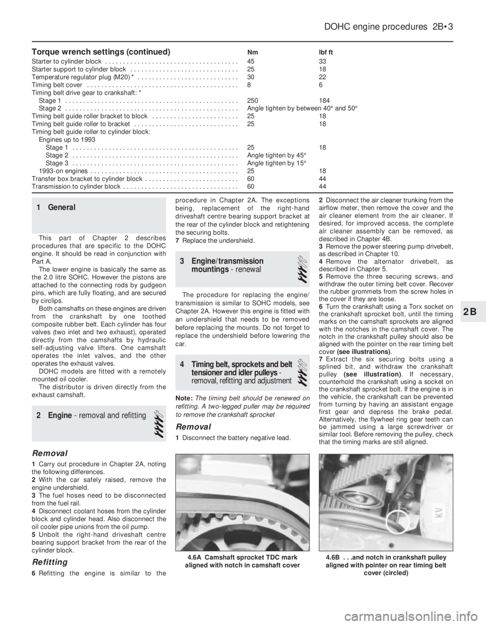
6Turn the crankshaft using a Torx socket on
the crankshaft sprocket bolt, until the timing
marks on the camshaft sprockets are aligned
with the notches in the camshaft cover. The
notch in the crankshaft pulley should also be
aligned with the pointer on the rear timing belt
cover (see illustrations).
7Extract the six securing bolts using a
splined bit, and withdraw the crankshaft
pulley (see illustration). If necessary,
counterhold the crankshaft using a socket on
the crankshaft sprocket bolt. If the engine is in
the vehicle, the crankshaft can be prevented
from turning by having an assistant engage
first gear and depress the brake pedal.
Alternatively, the flywheel ring gear teeth can
be jammed using a large screwdriver or
similar tool. Before removing the pulley, check
that the timing marks are still aligned.
DOHC engine procedures 2B•3
4.6B . . .and notch in crankshaft pulley
aligned with pointer on rear timing belt
cover (circled)4.6A Camshaft sprocket TDC mark
aligned with notch in camshaft cover
2B
Page 191 of 525
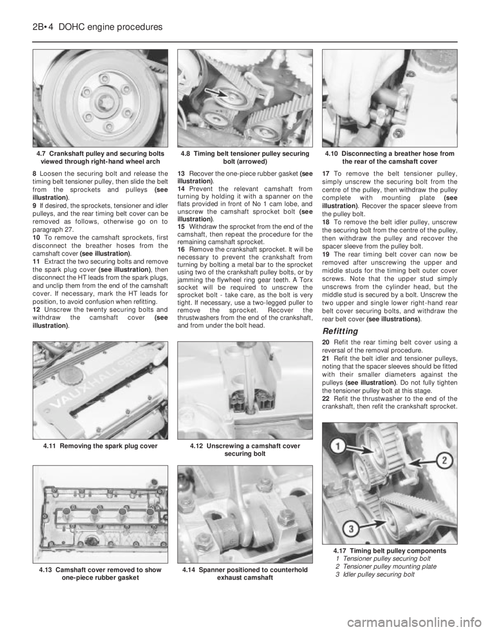
8Loosen the securing bolt and release the
timing belt tensioner pulley, then slide the belt
from the sprockets and pulleys (see
illustration).
9If desired, the sprockets, tensioner and idler
pulleys, and the rear timing belt cover can be
removed as follows, otherwise go on to
paragraph 27.
10To remove the camshaft sprockets, first
disconnect the breather hoses from the
camshaft cover (see illustration).
11Extract the two securing bolts and remove
the spark plug cover (see illustration), then
disconnect the HT leads from the spark plugs,
and unclip them from the end of the camshaft
cover. If necessary, mark the HT leads for
position, to avoid confusion when refitting.
12Unscrew the twenty securing bolts and
withdraw the camshaft cover (see
illustration).13Recover the one-piece rubber gasket (see
illustration).
14Prevent the relevant camshaft from
turning by holding it with a spanner on the
flats provided in front of No 1 cam lobe, and
unscrew the camshaft sprocket bolt (see
illustration).
15Withdraw the sprocket from the end of the
camshaft, then repeat the procedure for the
remaining camshaft sprocket.
16Remove the crankshaft sprocket. It will be
necessary to prevent the crankshaft from
turning by bolting a metal bar to the sprocket
using two of the crankshaft pulley bolts, or by
jamming the flywheel ring gear teeth. A Torx
socket will be required to unscrew the
sprocket bolt -take care, as the bolt is very
tight. If necessary, use a two-legged puller to
remove the sprocket. Recover the
thrustwashers from the end of the crankshaft,
and from under the bolt head.17To remove the belt tensioner pulley,
simply unscrew the securing bolt from the
centre of the pulley, then withdraw the pulley
complete with mounting plate (see
illustration). Recover the spacer sleeve from
the pulley bolt.
18To remove the belt idler pulley, unscrew
the securing bolt from the centre of the pulley,
then withdraw the pulley and recover the
spacer sleeve from the pulley bolt.
19The rear timing belt cover can now be
removed after unscrewing the upper and
middle studs for the timing belt outer cover
screws. Note that the upper stud simply
unscrews from the cylinder head, but the
middle stud is secured by a bolt. Unscrew the
two upper and single lower right-hand rear
belt cover securing bolts, and withdraw the
rear belt cover (see illustrations).
Refitting
20Refit the rear timing belt cover using a
reversal of the removal procedure.
21Refit the belt idler and tensioner pulleys,
noting that the spacer sleeves should be fitted
with their smaller diameters against the
pulleys (see illustration). Do not fully tighten
the tensioner pulley bolt at this stage.
22Refit the thrustwasher to the end of the
crankshaft, then refit the crankshaft sprocket.
2B•4DOHC engine procedures
4.7 Crankshaft pulley and securing bolts
viewed through right-hand wheel arch4.10 Disconnecting a breather hose from
the rear of the camshaft cover
4.17 Timing belt pulley components
1 Tensioner pulley securing bolt
2 Tensioner pulley mounting plate
3 Idler pulley securing bolt
4.14 Spanner positioned to counterhold
exhaust camshaft4.13 Camshaft cover removed to show
one-piece rubber gasket
4.12 Unscrewing a camshaft cover
securing bolt4.11 Removing the spark plug cover
4.8 Timing belt tensioner pulley securing
bolt (arrowed)
Page 202 of 525
18 SV, C18 NZ, 20 NE, C20 NE and 20 SEH:
New belt, cold . . . . . . . . . . . . . . . . . . . . . . . . . . . . . . . . . . . . . . . . .4.5
New belt, warm . . . . . . . . . . . . . . . . . . . . . . . . . . . . . . . . . . . . . . . .7.5
Used belt, cold . . . . . . . . . . . . . . . . . . . . . . . . . . . . . . . . . . . . . . . .2.5
Used belt, warm . . . . . . . . . . . . . . . . . . . . . . . . . . . . . . . . . . . . . . .7.0
Valves and guidesInletExhaust
Overall length - production (mm):
14 NV . . . . . . . . . . . . . . . . . . . . . . . . . . . . . . . . . . . . . . . . . . . . . . . . .105.0105.0
16 SV, X 16 SZ and C16 NZ . . . . . . . . . . . . . . . . . . . . . . . . . . . . . . .101.5101.5
C16 NZ2 . . . . . . . . . . . . . . . . . . . . . . . . . . . . . . . . . . . . . . . . . . . . . . .104.2104.2
18 SV, C18 NZ, 20 NE, C20 NE and 20 SEH . . . . . . . . . . . . . . . . . . .104.2104.0
Overall length - service (mm):
14 NV . . . . . . . . . . . . . . . . . . . . . . . . . . . . . . . . . . . . . . . . . . . . . . . . .104.6104.6
16 SV, X 16 SZ and C16 NZ . . . . . . . . . . . . . . . . . . . . . . . . . . . . . . .101.1101.1
C16 NZ2 . . . . . . . . . . . . . . . . . . . . . . . . . . . . . . . . . . . . . . . . . . . . . . .103.8103.8
18 SV, C18 NZ, 20 NE, C20 NE and 20 SEH . . . . . . . . . . . . . . . . . . .103.8103.6
Head diameter (mm):
14 NV . . . . . . . . . . . . . . . . . . . . . . . . . . . . . . . . . . . . . . . . . . . . . . . . .33.029.0
16 SV, X 16 SZ, C16 NZ and C16 NZ2 . . . . . . . . . . . . . . . . . . . . . . . .38.031.0
18 SV, C18 NZ, 20 NE, C20 NE and 20 SEH . . . . . . . . . . . . . . . . . . .41.836.5
Stem diameter (mm), (all engines):
Standard . . . . . . . . . . . . . . . . . . . . . . . . . . . . . . . . . . . . . . . . . . . . . . .6.998 to 7.0126.978 to 6.992
0.075 mm oversize . . . . . . . . . . . . . . . . . . . . . . . . . . . . . . . . . . . . . . .7.073 to 7.0877.053 to 7.067
0.150 mm oversize . . . . . . . . . . . . . . . . . . . . . . . . . . . . . . . . . . . . . . .7.148 to 7.1627.128 to 7.142
0.250 mm oversize . . . . . . . . . . . . . . . . . . . . . . . . . . . . . . . . . . . . . . .7.248 to 7.2627.228 to 7.242
Valve guide bore (mm), (all engines):
Standard . . . . . . . . . . . . . . . . . . . . . . . . . . . . . . . . . . . . . . . . . . . . . . .7.030 to 7.050
0.075 mm oversize . . . . . . . . . . . . . . . . . . . . . . . . . . . . . . . . . . . . . . .7.105 to 7.125
0.150 mm oversize . . . . . . . . . . . . . . . . . . . . . . . . . . . . . . . . . . . . . . .7.180 to 7.200
0.250 mm oversize . . . . . . . . . . . . . . . . . . . . . . . . . . . . . . . . . . . . . . .7.280 to 7.300
Valve clearance in guide (mm), (all engines):
Inlet . . . . . . . . . . . . . . . . . . . . . . . . . . . . . . . . . . . . . . . . . . . . . . . . . . .0.018 to 0.052
Exhaust . . . . . . . . . . . . . . . . . . . . . . . . . . . . . . . . . . . . . . . . . . . . . . . .0.038 to 0.072
Valve seat angle:
All models . . . . . . . . . . . . . . . . . . . . . . . . . . . . . . . . . . . . . . . . . . . . . .44º
Valve clearances:
All models . . . . . . . . . . . . . . . . . . . . . . . . . . . . . . . . . . . . . . . . . . . . . .Automatic adjustment by hydraulic lifters
Flywheel
Maximum permissible lateral run-out of starter ring gear (all models) . .0.5 mm
Refinishing limit -maximum depth of material that may be removed
from clutch friction surface (all models) . . . . . . . . . . . . . . . . . . . . . . .0.3 mm
Lubrication system
Lubricant type/specification . . . . . . . . . . . . . . . . . . . . . . . . . . . . . . . . . .See Lubricants and fluids in “Weekly checks”
Lubricant capacity . . . . . . . . . . . . . . . . . . . . . . . . . . . . . . . . . . . . . . . . .See Chapter 1 Specifications
Oil pump clearances:
Inner-to-outer gear teeth clearance (backlash) (all models) . . . . . . . .0.0 to 0.2 mm
Gear-to-housing clearance (endfloat):
14 NV, 16 SV, C16 NZ and X 16 SZ . . . . . . . . . . . . . . . . . . . . . . . .0.08 to 0.15 mm
C16 NZ2, 18 SV, C18 NZ, 20 NE, C20 NE and 20 SEH . . . . . . . . .0.03 to 0.10 mm
Oil pressure at idle (engine warm) (all models) . . . . . . . . . . . . . . . . . . . .1.5 bar (21.8 lbf/in2
)
Torque wrench settingsNmlbf ft
Note:Use new bolts where asterisked (*). The torque settings stated for the cylinder head are only applicable to latest specification bolts, available
from Vauxhall. Earlier type or alternative make, head bolts may require different torques. Consult your supplier.
Air inlet pre-heat to exhaust manifold . . . . . . . . . . . . . . . . . . . . . . . . . .86
Alternator and inlet manifold to brackets:
1.4 and 1.6 litre, (except C16 NZ2) . . . . . . . . . . . . . . . . . . . . . . . . . . .2015
C16 NZ2, 1.8 and 2.0 litre . . . . . . . . . . . . . . . . . . . . . . . . . . . . . . . . . .1813
Alternator to bracket (M8) . . . . . . . . . . . . . . . . . . . . . . . . . . . . . . . . . . . .3022
Alternator to bracket (M10) . . . . . . . . . . . . . . . . . . . . . . . . . . . . . . . . . . .4030
Alternator to shackle . . . . . . . . . . . . . . . . . . . . . . . . . . . . . . . . . . . . . . . .2518
Big-end bearing cap: *
1.4 and 1.6 litre, (except C16 NZ2)
Stage 1 . . . . . . . . . . . . . . . . . . . . . . . . . . . . . . . . . . . . . . . . . . . . . .2518
Stage 2 . . . . . . . . . . . . . . . . . . . . . . . . . . . . . . . . . . . . . . . . . . . . . .Angle tighten by 30º
SOHC engine procedures 2A•5
2A
Page 206 of 525
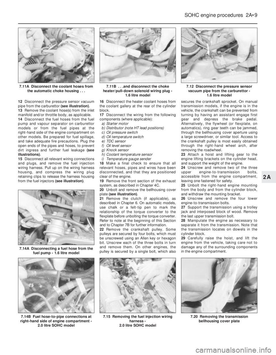
12Disconnect the pressure sensor vacuum
pipe from the carburettor (see illustration).
13Remove the coolant hose(s) from the inlet
manifold and/or throttle body, as applicable.
14Disconnect the fuel hoses from the fuel
pump and vapour separator on carburettor
models or from the fuel pipes at the
right-hand side of the engine compartment on
other models. Be prepared for fuel spillage,
and take adequate fire precautions. Plug the
open ends of the pipes and hoses, to prevent
dirt ingress and further fuel leakage (see
illustrations).
15Disconnect all relevant wiring connections
and plugs, and remove the fuel injection
wiring harness. Pull up on the wiring harness
housing, and compress the wiring plug
retaining clips to release the harness housing
from the fuel injectors (see illustration).16Disconnect the heater coolant hoses from
the coolant gallery at the rear of the cylinder
block.
17Disconnect the wiring from the following
components (where applicable):
a)Starter motor
b)Distributor (note HT lead positions)
c)Oil pressure switch
d)Oil temperature switch
e)TDC sensor
f)Oil level sensor
g)Knock sensor
h)Coolant temperature sensor
i)Temperature gauge sender
18Make a final check to ensure that all
relevant hoses, pipes and wires have been
disconnected, and that they are positioned
clear of the engine.
19Remove the front section of the exhaust
system, as described in Chapter 4C.
20Unbolt and remove the bellhousing cover
plate (see illustration).
21Remove the clutch (if applicable), as
described in Chapter 6. On automatic models,
use chalk or a felt-tip pen to mark the
relationship of the torque converter to the
flexplate before unbolting the torque converter.
Refer to note at the beginning of this Section
and to Chapter 7B for further information.
22Remove the crankshaft pulley. Some
pulleys are secured by four bolts, which must
be unscrewed using an Allen key or hexagon
bit. Unscrew each of the three bolts in turn
and remove them. On other engines, the
pulley is secured by a single bolt, which alsosecures the crankshaft sprocket. On manual
transmission models, if the engine is in the
vehicle, the crankshaft can be prevented from
turning by having an assistant engage first
gear and depress the brake pedal.
Alternatively, the flywheel (or flexplate, on
automatics), ring gear teeth can be jammed,
through the bellhousing cover aperture using
a large screwdriver, or similar tool. Access to
the crankshaft pulley is most easily obtained
through the right-hand wheel arch, after
removing the roadwheel.
23Attach a hoist and lifting gear to the
engine lifting brackets on the cylinder head,
and support the weight of the engine.
24Unscrew and remove two of the three
upper engine-to-transmission bolts,
accessible from the engine compartment,
leaving one fastened for safety.
25Unbolt the right-hand engine mounting
from the body and from the cylinder block,
and withdraw the mounting bracket.
26Unscrew and remove the four lower
engine-to-transmission bolts.
27Support the transmission using a trolley
jack and interposed block of wood. Remove
the last upper transmission bolt.
28Manipulate the engine as necessary to
separate it from the transmission. Note that
the transmission locates on dowels in the
cylinder block.
29Carefully raise the hoist, and lift the
engine from the vehicle, taking care not to
damage any of the surrounding components
in the engine compartment.
SOHC engine procedures 2A•9
7.12 Disconnect the pressure sensor
vacuum pipe from the carburettor -
1.6 litre model
7.20 Removing the transmission
bellhousing cover plate7.15 Removing the fuel injection wiring
harness -
2.0 litre SOHC model7.14B Fuel hose-to-pipe connections at
right-hand side of engine compartment -
2.0 litre SOHC model
7.14A Disconnecting a fuel hose from the
fuel pump - 1.6 litre model
7.11B . . .and disconnect the choke
heater/pull-down solenoid wiring plug -
1.6 litre model7.11A Disconnect the coolant hoses from
the automatic choke housing . . .
2A
Page 207 of 525
30With the engine removed, the
transmission can be supported by placing a
length of wood between the bellhousing and
the front suspension subframe. Once the
wooden support is in place, remove the trolley
jack from under the transmission.
Refitting
Note: New left and right-hand
engine/transmission mounting-to-body bolts
must be used on refitting.
31Use an M10 x 1.25 bottoming tap to clean
the threads in the torque converters threaded
bosses and ensure that new bolts are
available for reassembly, where applicable.
32Support the transmission with a trolley
jack and remove the length of wood from
between the bellhousing and the subframe.
33Support the engine with the hoist and
lifting tackle, and gently lower it into position
in the engine compartment.
34Mate the engine and transmission
together, ensuring that the transmission
locates on the dowels in the cylinder block,
then refit the three upper
engine-to-transmission bolts.
35Tighten all nuts and bolts to their specified
torque wrench settings. When tightening the
torque converter-to-flexplate bolts to their
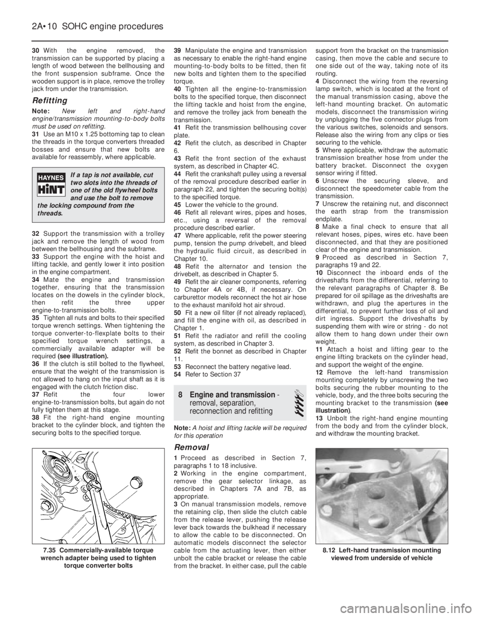
specified torque wrench settings, a
commercially available adapter will be
required (see illustration).
36If the clutch is still bolted to the flywheel,
ensure that the weight of the transmission is
not allowed to hang on the input shaft as it is
engaged with the clutch friction disc.
37Refit the four lower
engine-to-transmission bolts, but again do not
fully tighten them at this stage.
38Fit the right-hand engine mounting
bracket to the cylinder block, and tighten the
securing bolts to the specified torque.39Manipulate the engine and transmission
as necessary to enable the right-hand engine
mounting-to-body bolts to be fitted, then fit
new bolts and tighten them to the specified
torque.
40Tighten all the engine-to-transmission
bolts to the specified torque, then disconnect
the lifting tackle and hoist from the engine,
and remove the trolley jack from beneath the
transmission.
41Refit the transmission bellhousing cover
plate.
42Refit the clutch, as described in Chapter
6.
43Refit the front section of the exhaust
system, as described in Chapter 4C.
44Refit the crankshaft pulley using a reversal
of the removal procedure described earlier in
paragraph 22, and tighten the securing bolt(s)
to the specified torque.
45Lower the vehicle to the ground.
46Refit all relevant wires, pipes and hoses,
etc., using a reversal of the removal
procedure described earlier.
47Where applicable, refit the power steering
pump, tension the pump drivebelt, and bleed
the hydraulic fluid circuit, as described in
Chapter 10.
48Refit the alternator and tension the
drivebelt, as described in Chapter 5.
49Refit the air cleaner components, referring
to Chapter 4A or 4B, if necessary. On
carburettor models reconnect the hot air hose
to the exhaust manifold hot air shroud.
50Fit a new oil filter (if not already replaced),
and fill the engine with oil, as described in
Chapter 1.
51Refit the radiator and refill the cooling
system, as described in Chapter 3.
52Refit the bonnet as described in Chapter
11.
53Reconnect the battery negative lead.
54Refer to Section 37
8Engine and transmission -
removal, separation,
reconnection and refitting
4
Note: A hoist and lifting tackle will be required
for this operation
Removal
1Proceed as described in Section 7,
paragraphs 1 to 18 inclusive.
2Working in the engine compartment,
remove the gear selector linkage, as
described in Chapters 7A and 7B, as
appropriate.
3On manual transmission models, remove
the retaining clip, then slide the clutch cable
from the release lever, pushing the release
lever back towards the bulkhead if necessary
to allow the cable to be disconnected. On
automatic models disconnect the selector
cable from the actuating lever, then either
unbolt the cable bracket or release the cable
from the bracket. In either case, pull the cablesupport from the bracket on the transmission
casing, then move the cable and secure to
one side out of the way, taking note of its
routing.
4Disconnect the wiring from the reversing
lamp switch, which is located at the front of
the manual transmission casing, above the
left-hand mounting bracket. On automatic
models, disconnect the transmission wiring
by unplugging the five connector plugs from
the various switches, solenoids and sensors.
Release also the wiring from any clips or ties
securing to the vehicle.
5Where applicable, withdraw the automatic
transmission breather hose from under the
battery bracket. Disconnect the oxygen
sensor wiring if fitted.
6Unscrew the securing sleeve, and
disconnect the speedometer cable from the
transmission.
7Unscrew the retaining nut, and disconnect
the earth strap from the transmission
endplate.
8Make a final check to ensure that all
relevant hoses, pipes, wires etc. have been
disconnected, and that they are positioned
clear of the engine and transmission.
9Proceed as described in Section 7,
paragraphs 19 and 22.
10Disconnect the inboard ends of the
driveshafts from the differential, referring to
the relevant paragraphs of Chapter 8. Be
prepared for oil spillage as the driveshafts are
withdrawn, and plug the apertures in the
differential, to prevent further loss of oil and
dirt ingress. Support the driveshafts by
suspending them with wire or string - do not
allow them to hang down under their own
weight.
11Attach a hoist and lifting gear to the
engine lifting brackets on the cylinder head,
and support the weight of the engine.
12Remove the left-hand transmission
mounting completely by unscrewing the two
bolts securing the rubber mounting to the
vehicle, body, and the three bolts securing the
mounting bracket to the transmission (see
illustration).
13Unbolt the right-hand engine mounting
from the body and from the cylinder block,
and withdraw the mounting bracket.
2A•10SOHC engine procedures
8.12 Left-hand transmission mounting
viewed from underside of vehicle7.35 Commercially-available torque
wrench adapter being used to tighten
torque converter bolts
If a tap is not available, cut
two slots into the threads of
one of the old flywheel bolts
and use the bolt to remove
the locking compound from the
threads.
Page 208 of 525
14Working under the vehicle, unscrew and
remove the two nuts securing the
engine/transmission rear mounting to the front
subframe, and the three bolts securing the
mounting bracket to the transmission, then
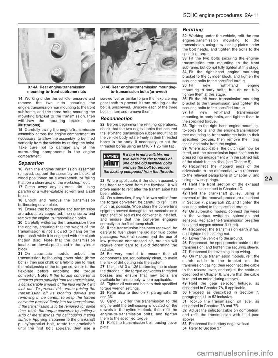
withdraw the mounting bracket (see
illustrations).
15Carefully swing the engine/transmission
assembly across the engine compartment as
necessary, to allow the assembly to be lifted
vertically from the vehicle by raising the hoist.
Take care not to damage any of the
surrounding components in the engine
compartment.
Separation
16With the engine/transmission assembly
removed, support the assembly on blocks of
wood positioned on a workbench, or failing
that, on a clean area of the workshop floor.
17Clean away any external dirt using
paraffin or a water-soluble solvent and a stiff
brush.
18Unbolt and remove the transmission
bellhousing cover plate.
19Ensure that both engine and transmission
are adequately supported, then unscrew and
remove the engine-to-transmission bolts.
20Carefully withdraw the transmission from
the engine, ensuring that the weight of the
transmission is not allowed to hang on the
input shaft while it is engaged with the clutch
friction disc. Note that the transmission
locates on dowels positioned in the cylinder
block.
21On automatic models unbolt the
transmission bellhousing cover plate (three
bolts), then use chalk or a felt-tip pen to mark
the relationship of the torque converter to the
flexplate before unbolting the torque
converter. Note:If the torque converter is
removed (even partially) from the transmission,
a considerable amount of the fluid inside it will
leak out. To prevent this, when prising the
transmission off its locating dowels and
removing it, be careful to keep the torque
converter pressed firmly into the transmission.
If the transmission is to be removed for some
time, retain the torque converter by bolting a
strip of metal across the bellhousing mating
surface. Applying a spanner to the crankshaft
pulley/sprocket bolt, rotate the crankshaft
until the first bolt appears, then use ascrewdriver or similar to jam the flexplate ring
gear teeth to prevent it from rotating as the
bolt is unscrewed. Unscrew each of the three
bolts in turn and remove them.
Reconnection
22Before beginning the refitting operations,
check that the two original bolts that secured
the left-hand transmission rubber mounting to
the vehicle body rotate freely in their threaded
bores in the body. If necessary, re-cut the
threaded bores using an M10 x 1.25 mm tap.
23Where applicable, if the clutch assembly
has been removed from the flywheel, it will
prove easier to refit after the transmission has
been refitted.
24On automatics, if any fluid was spilled from
the torque converter, be careful to refill it as
much as possible. Wipe clean the converter’s
spigot to prevent damage to the transmission’s
input shaft oil seal as the converter is installed,
and ensure that the converter engages
correctly on the fluid pump shaft.
25If the transmission has been renewed, be
careful to flush clean the radiator fluid cooler
passages. Vauxhall recommend the use of
low-pressure compressed air, but this will
require great care to avoid deforming the
radiator.
26Be very careful to ensure that all
components are scrupulously clean, to avoid
the risk of dirt getting into the system.
27Use an M10 x 1.25 bottoming tap to clean
the threads in the torque converters threaded
bosses and ensure that new bolts are
available for reassembly, where applicable.
28Tighten all nuts and bolts to their specified
torque wrench settings.
29Refer also to Section 7, paragraphs 35
and 36.
30Carefully offer the transmission to the
engine until the bellhousing is located on the
dowels in the cylinder block, then refit the
engine-to-transmission bolts, and tighten
them to the specified torque.
31Refit the transmission bellhousing cover
plate.
Refitting
32Working under the vehicle, refit the rear
engine/transmission mounting to the
transmission, using new locking plates under
the bolt heads, and tighten the bolts to the
specified torque.
33Fit the two bolts securing the engine/
transmission rear mounting to the front
subframe, but do not fully tighten at this stage.
34Fit the right-hand engine mounting
bracket to the cylinder block, and tighten the
securing bolts to the specified torque.
35Fit new right-hand engine
mounting-to-body bolts, but do not fully
tighten them at this stage.
36Fit the left-hand transmission mounting
bracket to the transmission, and tighten the
securing bolts to the specified torque.
37Fit new left-hand transmission
mounting-to-body bolts, and tighten them to
the specified torque.
38Tighten the right-hand engine mounting-
to-body bolts and the engine/transmission
rear mounting-to-front subframe bolts to their
specified torques, then remove the lifting
tackle and hoist from the engine.
39Where applicable, the clutch can now be
fitted, and the transmission input shaft can be
pressed into engagement with the splined hub
of the clutch friction disc, (see Chapter 5).
40Reconnect the inboard ends of the
driveshafts to the differential, with reference
to the relevant paragraphs of Chapter 8, and
using new snap rings.
41Refit the front section of the exhaust
system, as described in Chapter 4C.
42Refit the crankshaft pulley, using a
reversal of the removal procedure described
in Section 7, paragraph 22, and tighten the
securing bolt(s) to the specified torque.
43On automatic models, connect the wires
to the various switches, solenoids and
sensors. Replace the transmission breather
hose and oxygen sensor (if fitted).
44Reconnect the transmission earth strap,
and tighten the securing nut.
45Lower the vehicle to the ground.
46Reconnect the speedometer cable to the
transmission, and tighten the securing sleeve.
47Reconnect the reversing lamp wiring.
48On manual transmission models, refit the
clutch cable to the bracket on the
transmission casing, then reconnect the cable
to the release lever, and adjust the cable as
described in Chapter 6. Ensure that the cable
is routed as noted during removal.
49Refit the gear selector linkage, as
described in Chapter 7A, if applicable.
50Proceed as described in Section 7,
paragraphs 41 to 52 inclusive.
51Top-up the transmission oil level, as
described in Chapters 7A and 7B.
52Adjust the selector cable on completion,
and refill the transmission with fluid (see
above).
53Reconnect the battery negative lead.
54Refer to Section 37
SOHC engine procedures 2A•11
8.14B Rear engine/transmission mounting-
to-transmission bolts (arrowed)8.14A Rear engine/transmission
mounting-to-front subframe nuts
2A
If a tap is not available, cut
two slots into the threads of
one of the old flywheel bolts
and use the bolt to remove
the locking compound from the threads.
Page 209 of 525
9Engine and transmission
mountings - renewal
3
Note: New left and right-hand
engine/transmission mounting-to-body bolts
must be used on refitting
1The engine/transmission assembly is
suspended in the engine compartment on
three mountings, two of which are attached to
the transmission, and one to the engine.
Right-hand mounting
2If not already done, apply the handbrake,
then raise the front of the vehicle, and support
securely on axle stands (see “Jacking and
Vehicle Support”)..
3Attach lifting tackle and a hoist to the
engine lifting brackets on the cylinder head,
and support the weight of the engine.
4Working under the vehicle, unbolt the
engine mounting bracket from the cylinder
block, and unbolt the mounting block from the
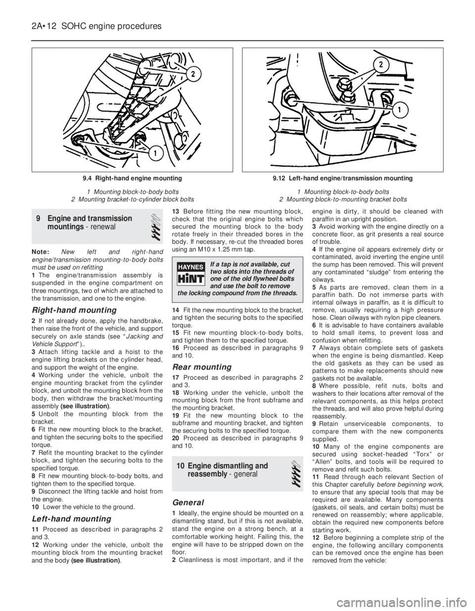
body, then withdraw the bracket/mounting
assembly (see illustration).
5Unbolt the mounting block from the
bracket.
6Fit the new mounting block to the bracket,
and tighten the securing bolts to the specified
torque.
7Refit the mounting bracket to the cylinder
block, and tighten the securing bolts to the
specified torque.
8Fit new mounting block-to-body bolts, and
tighten them to the specified torque.
9Disconnect the lifting tackle and hoist from
the engine.
10Lower the vehicle to the ground.
Left-hand mounting
11Proceed as described in paragraphs 2
and 3.
12Working under the vehicle, unbolt the
mounting block from the mounting bracket
and the body (see illustration).13Before fitting the new mounting block,
check that the original engine bolts which
secured the mounting block to the body
rotate freely in their threaded bores in the
body. If necessary, re-cut the threaded bores
using an M10 x 1.25 mm tap.
14Fit the new mounting block to the bracket,
and tighten the securing bolts to the specified
torque.
15Fit new mounting block-to-body bolts,
and tighten them to the specified torque.
16Proceed as described in paragraphs 9
and 10.
Rear mounting
17Proceed as described in paragraphs 2
and 3.
18Working under the vehicle, unbolt the
mounting block from the front subframe and
the mounting bracket.
19Fit the new mounting block to the
subframe and mounting bracket, and tighten
the securing bolts to the specified torque.
20Proceed as described in paragraphs 9
and 10.
10Engine dismantling and
reassembly - general
4
General
1Ideally, the engine should be mounted on a
dismantling stand, but if this is not available,
stand the engine on a strong bench, at a
comfortable working height. Failing this, the
engine will have to be stripped down on the
floor.
2Cleanliness is most important, and if theengine is dirty, it should be cleaned with
paraffin in an upright position.
3Avoid working with the engine directly on a
concrete floor, as grit presents a real source
of trouble.
4If the engine oil appears extremely dirty or
contaminated, avoid inverting the engine until
the sump has been removed. This will prevent
any contaminated “sludge” from entering the
oilways.
5As parts are removed, clean them in a
paraffin bath. Do not immerse parts with
internal oilways in paraffin, as it is difficult to
remove, usually requiring a high pressure
hose. Clean oilways with nylon pipe cleaners.
6It is advisable to have containers available
to hold small items, to prevent loss and
confusion when refitting.
7Always obtain complete sets of gaskets
when the engine is being dismantled. Keep
the old gaskets as they can be used as
patterns to make replacements should new
gaskets not be available.
8Where possible, refit nuts, bolts and
washers to their locations after removal of the
relevant components, as this helps protect
the threads, and will also prove helpful during
reassembly.
9Retain unserviceable components, to
compare them with the new components
supplied.
10Many of the engine components are
secured using socket-headed “Torx” or
“Allen” bolts, and tools will be required to
remove and refit such bolts.
11Read through each relevant Section of
this Chapter carefullybeforebeginning work,
to ensure that any special tools that may be
required are available. Many components
(gaskets, oil seals, and certain bolts) must be
renewed on reassembly; where applicable,
obtain the required new components before
starting work.
12Before beginning a complete strip of the
engine, the following ancillary components
can be removed once the engine has been
removed from the vehicle:
2A•12SOHC engine procedures
9.4 Right-hand engine mounting
1 Mounting block-to-body bolts
2 Mounting bracket-to-cylinder block bolts9.12 Left-hand engine/transmission mounting
1 Mounting block-to-body bolts
2 Mounting block-to-mounting bracket bolts
If a tap is not available, cut
two slots into the threads of
one of the old flywheel bolts
and use the bolt to remove
the locking compound from the threads.